Table of Contents
Advertisement
Quick Links
Download this manual
See also:
User Manual
Advertisement
Table of Contents

Related Manuals for Winmate R17IH3S-MLA1-89


Summary of Contents for Winmate R17IH3S-MLA1-89
- Page 1 Rack Mount Panel PC 17”/ 19”/ 24” touchscreen, with Intel® Core i7 4650U 3.30GHz processor Military Grade R17IH3S-MLA1-89 Model No: R19IH3S-MLA3-89 W24IH3S-MLS1-89 User Manual Version 1.0 Document Part Number: 9152111I100U...
-
Page 2: Copyright Notice
Preface Copyright Notice No part of this document may be reproduced, copied, translated, or transmitted in any form or by any means, electronic or mechanical, for any purpose, without the prior written permission of the original manufacturer. Trademark Acknowledgement Brand and product names are trademarks or registered trademarks of their respective owners. - Page 3 Customer Service We provide a service guide for any problem by the following steps: First, visit the website of our distributor to find the update information about the product. Second, contact with your distributor, sales representative, or our customer service center for technical support if you need additional assistance.
- Page 4 Advisory Conventions Four types of advisories are used throughout the user manual to provide helpful information or to alert you to the potential for hardware damage or personal injury. These are Notes, Important, Cautions, and Warnings. The following is an example of each type of advisory. NOTE: A note is used to emphasize helpful information IMPORTANT:...
-
Page 5: Safety Information
Safety Information WARNING! / AVERTISSEMENT! Always completely disconnect the power cord from your chassis whenever you work with the hardware. Do not make connections while the power is on. Sensitive electronic components can be damaged by sudden power surges. Only experienced electronics personnel should open the PC chassis. Toujours débrancher le cordon d’alimentation du chassis lorsque vous travaillez sur celui-ci. -
Page 6: Safety Precautions
Safety Precautions For your safety carefully read all the safety instructions before using the device. All cautions and warnings on the equipment should be noted. Keep this user manual for future reference. CAUTION/ATTENTION Do not cover the openings! Ne pas couvrir les ouvertures! *Let service personnel to check the equipment in case any of the following problems appear: o The power cord or plug is damaged. -
Page 7: Important Information
Important Information Countries/ Symbol This equipment complies with essential requirements of: Area European Electromagnetic Compatibility Directive(2014/30/EU) Union Low Voltage Directive (2014/35/EU) Restrictions of the use of certain hazardous substances (RoHS) Directive (2011/65/EU) FCC Part 15 Subpart B Regulations Class B Federal Communications Commission Radio Frequency Interface Statement This device complies with part 15 FCC rules. - Page 8 European Union This equipment is in conformity with the requirement of the following EU legislations and harmonized standards. Product also complies with the Council directions. Electromagnetic Compatibility Directive (2014/30/EU) EN55024: 2010 EN 55022: 2010 Class B o IEC61000-4-2: 2009 o IEC61000-4-3: 2006+A1: 2007+A2: 2010 o IEC61000-4-4: 2012 o IEC61000-4-5: 2014...
- Page 9 Revision History Version Date Note Author 20-June-2016 Initial release Tom Huang User Manual...
-
Page 10: Table Of Contents
Contents Preface ............................ii 1 Introduction ..........................13 1.1 Product Features ........................ 13 1.2 Hardware Specifications ....................14 1.3 Software Support ....................... 15 1.4 Packing List ......................... 16 1.5 Appearance ........................17 1.5.1 Appearance ......................17 1.5.2 On-Screen Display Control ..................18 1.6 Dimensions ......................... - Page 11 6.3 Using Recovery Wizard to Restore Computer ..............81 7 Technical Support ........................84 7.1 Introduction ........................84 7.1.1 Winmate Download Center ..................84 7.1.2 Winmate File Share ....................84 7.2 Problem Report Form ......................85 Appendix A MIL-STD-810F/G Compliance ................... 87 A1 MIL-STD-810F/G Compliance .....................
- Page 12 Military Grade Rack Mount Panel PC Introduction Introduction This chapter gives you product overview, describes features and hardware specification. You will find all accessories that come with the Panel PC in the packing list. User Manual...
-
Page 13: Introduction
Military Grade Rack Mount Panel PC Introduction 1 Introduction Military Grade Panel PCs feature low power high performance CPU with fanless design. Anti-corrosive coating with aluminum alloy housing withstands the harshest military environments. Armored connectors MIL-DTL-38999 (type I and III) initially developed for aerospace industry perfectly fit in our Military grade product line. -
Page 14: Hardware Specifications
Military Grade Rack Mount Panel PC Introduction 1.2 Hardware Specifications Model Name R17IH3S-MLA1-89 R19IH3S-MLA3-89 W24IH3S-MLS1-89 Display: Size 17” 19” 24” Resolution 1280 x 1024 1280 x 1024 1920 x 1200 Brightness 350 cd/ (typ.) 350 cd/ (typ.) 300 cd/ (typ.) Contrast Ratio 1000:1 (typ.) -
Page 15: Software Support
Military Grade Rack Mount Panel PC Introduction 1.3 Software Support Winmate provide all necessary drivers and Software Development Kit (SDK). Drivers: Chipset Driver Graphics Driver Audio Driver Ethernet Driver Intel ® Management Engine Software USB 3.0 Driver (for Windows 7) -
Page 16: Packing List
Military Grade Rack Mount Panel PC Introduction 1.4 Packing List Carefully remove the box and unpack your device. Please check if all the items listed below are inside your package. If any of these items are missing or damaged contact us immediately. -
Page 17: Appearance
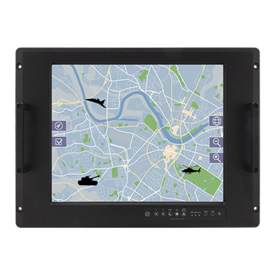
Military Grade Rack Mount Panel PC Introduction 1.5 Appearance This section includes appearance and input/ output connectors’ layout. 1.5.1 Appearance Display OSD Panel Ground VGA RS-232 AC IN USB 2.0 VESA M4 Nut User Manual... -
Page 18: On-Screen Display Control
Military Grade Rack Mount Panel PC Introduction 1.5.2 On-Screen Display Control On-Screen Display (OSD) is a user-friendly interface to remote the display function and to adjust the display’s image properties. It also supports special Hot Keys for easy control, such as auto-adjustment and brightness control for backlight. 1.5.2.1 Control Keys Icon Button... -
Page 19: Dimensions
Military Grade Rack Mount Panel PC Introduction 1.6 Dimensions This section includes mechanical drawing and dimensions of Panel PCs. 1.6.1 Dimensions 17” *Measurements shown in mm. **Tolerance of all dimensions is shown as follow 0~30 mm ± 0.1 mm, 30~50 mm ± 0.15 mm, 50~120 mm ±... -
Page 20: Dimensions 19
Military Grade Rack Mount Panel PC Introduction 1.6.2 Dimensions 19” *Measurements shown in mm. **Tolerance of all dimensions is shown as follow 0~30 mm ± 0.1 mm, 30~50 mm ± 0.15 mm, 50~120 mm ± 0.2 mm, above 120 mm ± 0.25 mm. ***Note: this is a simplified drawing and some components are not marked in detail. -
Page 21: Dimensions 24
Military Grade Rack Mount Panel PC Introduction 1.6.3 Dimensions 24” *Measurements shown in mm. **Tolerance of all dimensions is shown as follow 0~30 mm ± 0.1 mm, 30~50 mm ± 0.15 mm, 50~120 mm ± 0.2 mm, above 120 mm ± 0.25 mm. ***Note: this is a simplified drawing and some components are not marked in detail. -
Page 22: Getting Started
Military Grade Rack Mount Panel PC Getting Started Getting Started This chapter tells you important information on power supply, adapter and precautions tips. Pay attention to power considerations. User Manual... -
Page 23: Getting Started
Military Grade Rack Mount Panel PC Getting Started 2 Getting Started This chapter provides information on how to connect the device to the source of power, connector pinouts and the guideline to turn on/off the Panel PC. 2.1 Powering On 2.1.1 Power Considerations The device operates on external DC power. -
Page 24: Connecting The Power
Military Grade Rack Mount Panel PC Getting Started 2.1.2 Connecting the Power 2.1.2.1 Connecting to AC Input Power Source 1. Connect one end of the Military Grade power connector MIL-DTL-38999/1 to the Panel PC. 2. Plug the other end of the power connector in to a working AC outlet. WARNING!/ AVERTISSEMENT! Serious injury due to shock is possible if unit is wired incorrectly or connected to voltage exceeding the input voltage range. - Page 25 Military Grade Rack Mount Panel PC Getting Started 2.1.2.2 Connecting to DC Input Power Source 1. Insert the exposed wires of the DC Power Cable to the appropriate connectors on the terminal block plug. CAUTION/ ATTENTION Make sure that the polarization of the power lines is correct and complete including earth ground and PE.
-
Page 26: Connecting Other Devices
Military Grade Rack Mount Panel PC Getting Started 2.2 Connecting Other Devices Note that all the connectors are military grade and comply with military standard. The pin assignment of the cables are as follows. AC IN RS-232 USB 2.0 LAN WARNING!/ AVERTISSEMENT! Make sure the power is off when connecting and disconnecting the connectors. -
Page 27: Vga Connector
Military Grade Rack Mount Panel PC Getting Started 2.2.2 VGA Connector Plug one end of the 15-pin D-Sub signal cable (CN1) to the video signal MIL-DTL-38999/3 connector at the rear of the PC system and the other end (CN2) to the display. Pin №... -
Page 28: Usb 2.0 A Type Connector
Military Grade Rack Mount Panel PC Getting Started 2.2.4 USB 2.0 A Type Connector Connect USB 2.0 A type MIL-DTL-38999/3 connector to the external USB 2.0 compatible device, for example mouse or keyboard. Pin № Name Pin № Name Data- Data+ 2.2.5 LAN Connector Connect Ethernet MIL-DTL-38999/3 connector to Ethernet interface. - Page 29 Military Grade Rack Mount Panel PC Mounting Solutions Mounting Solutions This chapter provides mounting guide for all available mounting options. Pay attention to cautions and warning to avoid any damages. User Manual...
-
Page 30: Mounting Solutions
Military Grade Rack Mount Panel PC Mounting Solutions 3 Mounting Solutions This chapter provides mounting guide for all available mounting options. Pay attention to cautions and warning to avoid any damages. CAUTION/ ATTENTION Follow mounting instructions and use recommended mounting hardware to avoid the risk of injury. -
Page 31: Safety Precautions
Military Grade Rack Mount Panel PC Mounting Solutions 3.2 Safety Precautions Observe the following common safety precautions before installing any electronic device: •Use separate, non-intersecting paths to route power and networking wires. If power wiring and device wiring paths must be crossed make sure the wires are perpendicular at the intersection point. -
Page 32: Vesa Mount
4 x VESA M4 truss head screws 4 x VESA M4 mounting nuts NOTE: VESA Plate is not included in Winmate’s standard accessories package. Mounting Steps: 1. Locate the four mounting nuts at the back of the Panel PC. 2. Align the VESA plate to the four mounting nuts, placing the spacers between the VESA plate and the mounting nuts. - Page 33 Mounting Solutions 3. Using a spanner, insert the bolts through the VESA plate and spacers, tightly securing the bolts to the mounting nuts. 4. Continue with the instructions provided with your VESA-compatible wall bracket (not supplied by Winmate). User Manual...
- Page 34 Military Grade Rack Mount Panel PC Maintenance Maintenance This chapter provides information on regular cleaning and maintenance procedures. Follow all the recommendations included in this chapter in order to ensure long product lifecycle. User Manual...
-
Page 35: Maintenance
Military Grade Rack Mount Panel PC Maintenance 4 Maintenance This chapter includes regular cleaning and maintenance procedures. Follow all the recommendations in this chapter in order to ensure long product lifecycle. This equipment is extremely rugged and does not require a lot of maintenance. Remember that electrical equipment should be handled with care and used accordingly to its specifications. -
Page 36: Driver Installation
Military Grade Rack Mount Panel PC Driver Installation Driver Installation This chapter describes how to install all necessary drivers. User Manual... -
Page 37: Driver Installation
Military Grade Rack Mount Panel PC Driver Installation 5 Driver Installation This chapter provides guideline to driver installation. 5.1 Chipset Driver The Intel Chipset Drivers should be installed first before the software drivers enable Plug & Play INF support for Intel chipset components. Follow the instructions below to complete the installation. - Page 38 Military Grade Rack Mount Panel PC Driver Installation Step 2 Click “Next” to start the installation. Step 3 Click “Next” to continue the installation. User Manual...
- Page 39 Military Grade Rack Mount Panel PC Driver Installation Step 4 Click “Yes, I want to restart this computer now” to finish installation. User Manual...
-
Page 40: Graphics Driver
Military Grade Rack Mount Panel PC Driver Installation 5.2 Graphics Driver You need to install the Graphic driver to enable the function. Intel Graphic supports versatile display options and 32-bit 3D graphics engine. Triple independent display, enhanced display modes for widescreen flat panels for extend, twin, and clone display mode. - Page 41 Military Grade Rack Mount Panel PC Driver Installation Step 2 Click “Next” to install the driver. Step 3 Click “Yes” to agree with the license terms. User Manual...
- Page 42 Military Grade Rack Mount Panel PC Driver Installation Step 4 Click “Next” to install the driver. Step 5 Click “Yes, I want to restart this computer now” to finish installation. User Manual...
-
Page 43: Audio Driver
Military Grade Rack Mount Panel PC Driver Installation 5.3 Audio Driver The ALC886 series are high-performance 7.1+2 Channel High Definition Audio Codecs providing ten DAC channels that simultaneously support 7.1 sound playbacks, plus 2 channels of independent stereo sound output (multiple streaming) through the front panel stereo outputs. - Page 44 Military Grade Rack Mount Panel PC Driver Installation Step 3 Click “Yes, I want to restart my computer now” to finish the installation. User Manual...
-
Page 45: Ethernet Driver
Military Grade Rack Mount Panel PC Driver Installation 5.4 Ethernet Driver You must confirm which operating system is used on the IH32 Motherboard before installing the Ethernet drivers. Follow the steps below to complete the installation of the Intel® I210IT Gigabit-LAN Controller + I218LM Gigabit-LAN drivers. You will quickly complete the installation. - Page 46 Military Grade Rack Mount Panel PC Driver Installation Step 2 Extract the “PROWinX64_19.0” file and click “Next” to install the driver. Step 3 Click “Next” to agree with the license terms. User Manual...
- Page 47 Military Grade Rack Mount Panel PC Driver Installation Step 4 Click “Next” to install the driver. Step 5 Click “Finish” to complete the driver installation. User Manual...
-
Page 48: Intel® Management Engine Software
Military Grade Rack Mount Panel PC Driver Installation 5.5 Intel® Management Engine Software This installation program installs the Intel® ME software components required for the platform on which you are installing, and installs only those components that match your platform’s capabilities. Step 1 Insert the driver CD and select the “Intel ME 10.0”... - Page 49 Military Grade Rack Mount Panel PC Driver Installation Step 2 Click “Next” to continue the installation. Step 3 Click “Yes” to agree with the License terms. User Manual...
- Page 50 Military Grade Rack Mount Panel PC Driver Installation Step 4 Choose “I accept the terms of the license agreement”, and click “Next” to continue. Step 5 Click “Finish” to complete the software installation. User Manual...
-
Page 51: Usb 3.0 Driver Installation (Windows 7)
Military Grade Rack Mount Panel PC Driver Installation 5.6 USB 3.0 Driver Installation (Windows 7) NOTE: If the operating system of your device is Windows 10 IoT, Windows Embedded 8.1 Industry, Windows Embedded 8 Standard, users can skip this installation. Step 1 Locate the hard drive directory where the driver files are stored with the browser or the explore feature of Windows*. - Page 52 Military Grade Rack Mount Panel PC Driver Installation Step 4 Read the License Agreement and click “Yes” to proceed. Step 5 Review Readme File Information and click “Next” to proceed User Manual...
- Page 53 Military Grade Rack Mount Panel PC Driver Installation Step 6 When the Setup Progress is complete click “Next” to proceed. User Manual...
- Page 54 Military Grade Rack Mount Panel PC Driver Installation Step 7 Click “Yes, I want to restart this computer now” to finish and then restart your computer. User Manual...
- Page 55 Military Grade Rack Mount Panel PC BIOS Setup BIOS Setup BIOS Setup Utility is a program for configuration basic Input / Output system settings of the Panel PC for optimum use. This chapter provides information on how to use BIOS setup, its functions and menu. User Manual...
-
Page 56: Bios Setup
Military Grade Rack Mount Panel PC BIOS Setup 6 BIOS Setup 6.1 How and When to Use BIOS Setup To enter the BIOS setup, you need to connect an external USB keyboard, press Del key when the prompt appears on the screen during start up. The prompt screen shows only few seconds so need press Del key quickly. -
Page 57: Bios Functions
Military Grade Rack Mount Panel PC BIOS Setup 6.2 BIOS Functions The IH32 motherboard has AMI BIOS built-in and a CMOS SETUP utility that allow users to configure required settings or to activate certain system features. The follwoing sections describe the configuration options found in the menu items. 6.2.1 Main Menu The Main menu displays the basic information about yoursystem including BIOS version, processor RC version, system language, time, and date. -
Page 58: Advanced Settings
Military Grade Rack Mount Panel PC BIOS Setup 6.2.2 Advanced Settings Select the Advanced Tab from the IH32 setup menu to enter the advanced BIOS setup screen. You can select any of the items on the left frame of the screen to go to the sub menu for the item, such as CPU Configuration. - Page 59 Military Grade Rack Mount Panel PC BIOS Setup BIOS Setting Description Setting Effect Option ACPI Settings Configures ACPI settings Enter Opens submenu RTC Wake Settings Configures RTC Wake Enter Opens submenu parameters Trusted Computing Configures Trusted Enter Opens submenu Computing parameters CPU Configuration Configures CPU settings Enter...
- Page 60 Military Grade Rack Mount Panel PC BIOS Setup 6.2.2.1 ACPI Settings BIOS Setting Description Setting Option Effect Enable ACPI BIOS ACPI Auto Enable/ Disable Enables or Auto Configuration Disables this Configuration function Enable Control hibernation Enable/ Disable Enables or Hibernation Disables this function User Manual...
- Page 61 Military Grade Rack Mount Panel PC BIOS Setup 6.2.2.2 RTC Wake BIOS Setting Description Setting Option Effect Wake system with System awake on Enabled/ System will Fixed Time alarm events. Disabled awake at the hr: min: sec specified Wake system with S set the system to Enabled/ System will...
- Page 62 Military Grade Rack Mount Panel PC BIOS Setup 6.2.2.3 Trusted Computing BIOS Setting Description Setting Option Effect Security Device Enable or disable BIOS Enabled/Disabled Set desirable Support support for security device configuration TPM State Enable or disable TPM Enabled/Disabled Set desirable state.
- Page 63 Military Grade Rack Mount Panel PC BIOS Setup 6.2.2.4 CPU Configuration CPU Configuration allows you to change CPU settings. Use key arrows to navigate through the menu. User Manual...
- Page 64 Military Grade Rack Mount Panel PC BIOS Setup 6.2.2.5 SATA Configuration BIOS Setting Description Setting Option Effect SATA Controller (s) Allows users to enable Enabled/ Set desirable or disable the SATA Disabled configuration controller (s) SATA Mode Allows users to select Enabled/ Set desirable Selection...
- Page 65 Military Grade Rack Mount Panel PC BIOS Setup 6.2.2.6 Intel® Rapid Start Technology Allows users to enable or disable Intel rapid start technology. 6.2.2.7 PCH (FW) Configuration User Manual...
- Page 66 Military Grade Rack Mount Panel PC BIOS Setup 6.2.2.8 USB Configuration BIOS Setting Description Setting Option Effect Legacy USB User can enable or Disabled Will keep USB devices Support disable USB port. available only for EFI applications. Enabled Enable all the USB devices XHCI Hand‐off This is a workaround...
- Page 67 Military Grade Rack Mount Panel PC BIOS Setup Device Reset USB mass storage 10 Sec Depends on the time‐out time‐ out device start unit 20 Sec value command time‐ out. 30 Sec 40 Sec Device power‐ Maximum time the Auto Uses default value: for a up delay device will take before...
- Page 68 Military Grade Rack Mount Panel PC BIOS Setup 6.2.2.9 F81866 H/W Monitor BIOS Setting Description Setting Option Effect Smart Fan Set parameters of Enabled/ Enable or disable Function smart fan function Disabled this function Smart Fan Mode Configure smart fan mode settings Configuration User Manual...
- Page 69 Military Grade Rack Mount Panel PC BIOS Setup 6.2.2.10 F81866 Super IO Configuration BIOS Setting Description Setting Option Effect Setting Serial User can Enable/Disable Enable/Disable Enable or Port Parameters the serial port and select Disable Serial optimal settings for the Default: Port (COM).
- Page 70 Military Grade Rack Mount Panel PC BIOS Setup Pin 3~ Pin 10 Control Settings. User Manual...
- Page 71 Military Grade Rack Mount Panel PC BIOS Setup 6.2.2.11 Serial Port RS232/RS422/RS485 Settings BIOS Setting Description Setting Option Effect Serial Port Select Serial Port RS232 / RS422 Choose Serial RS485 (Rx)/ Port Settings RS485(Tx) Change Settings Allow Change Serial [AUTO] Port Settings UART Mode Show which serial port is used...
-
Page 72: Chipset Menu
Military Grade Rack Mount Panel PC BIOS Setup 6.2.3 Chipset Menu User Manual... - Page 73 Military Grade Rack Mount Panel PC BIOS Setup 6.2.3.1 PCH- IO Configuration BIOS Setting Description Setting Option Effect PCI Express Detail of PCI Express Set desirable Configuration items. parameters Set desirable Details of USB items Configuration parameters PCH LAN Enables or disables the Enabled/ Set desirable controller...
- Page 74 Military Grade Rack Mount Panel PC BIOS Setup 6.2.3.2 PCI Express Configuration BIOS Setting Description Setting Option Effect DMI Link ASPM Allows users to enable or Enabled/ Set desirable Control disable the DMI Link ASPM Disabled parameters Control DMI Link Allows users to configure Enabled/ Set desirable...
- Page 75 Military Grade Rack Mount Panel PC BIOS Setup 6.2.3.4 USB Configuration BIOS Setting Description Setting Option Effect Allows user to enable or Enabled/ Set desirable Precondition disable USB precondition Disabled parameters XHCI Mode Allows user to enable or [Smart Auto] Set desirable disable XHCI mode.
- Page 76 Military Grade Rack Mount Panel PC BIOS Setup 6.2.3.5 System Agent (SA) Configuration Allows users to enable or disable VT-d. User Manual...
- Page 77 Military Grade Rack Mount Panel PC BIOS Setup 6.2.3.6 Graphics Configuration BIOS Setting Description Graphics Turbo IMON Allows users to select which Graphics Turbo IMON Current Current Internal Graphics Allows users to enable or disable IGD Aperture Size This item allows users to select aperture size DVMT Pre-Allocated Allows users to select DVMT pre-allocated memory size...
-
Page 78: Boot Menu
Military Grade Rack Mount Panel PC BIOS Setup 6.2.4 Boot Menu The Boot menu sets the sequence of the devices to be searched for the operating system. The bootable devices will be automatically detected during POST and shown here, allowing you to set the sequence that the BIOS use to look for a boot device from which to load the operating system. -
Page 79: Security Menu
Military Grade Rack Mount Panel PC BIOS Setup Boot Option Specifies the overall boot order Ex: Boot Hard drive as Priorities from the available devices Option#1 the first priority (hard drive) 6.2.5 Security Menu This section allows to configure and improve system, and set up some system features according to your preferences. -
Page 80: Save & Exit
Military Grade Rack Mount Panel PC BIOS Setup 6.2.6 Save & Exit BIOS Setting Description Setting Effect Option Save Changes This saves the changes to the Enter <YES> Save changes and Exit CMOS and exits the BIOS Setup program. Discard This exits the BIOS Setup Enter <YES>... -
Page 81: Using Recovery Wizard To Restore Computer
Military Grade Rack Mount Panel PC BIOS Setup Save Changes Save changes done so far to any Enter <YES> Saves the of the setup options. changes Enter <NO> Return to the BIOS Setup Main Menu Discard Discard changes done so far to Enter <YES>... - Page 82 Military Grade Rack Mount Panel PC BIOS Setup Follow the procedure below to enable quick one-key recovery procedure: Plug-in the AC adapter to the Panel PC. Make sure the computer stays plugged in to power source during the recovery process ...
- Page 83 Military Grade Rack Mount Panel PC Technical Support Technical Support This chapter includes directory for technical support and Software Development Kit (SDK). User Manual...
-
Page 84: Technical Support
1_Chipset 2_Graphics 3_Audio 4_Network Connections 5_ME 6_USB3.0 Winmate provide the following SDK for Military Grade Rack Mount Panel PC with Intel® Core i7 4650U 3.30GHz processor: Item File Type Description Watchdog SDK To find the Drivers and SDK, please refer to the Driver CD that comes in the package or contact us. -
Page 85: Problem Report Form
Military Grade Rack Mount Panel PC Technical Support 7.2 Problem Report Form Military Grade Rack Mount Panel PC Customer name: Company: Tel.: Fax: E-mail: Date: Product Serial Number: _____________________________________________________ Problem Description: Please describe the problem as clearly as possible. Detailed description of the occurred problem will allow us to find the best solution to solve the problem as soon as possible. - Page 86 Military Grade Rack Mount Panel PC Appendices MIL-STD-810F/G Compliance This section includes information on testing methods and procedures in compliance with military standard MIL-STD-810 F/G. Appendix User Manual...
-
Page 87: Appendix A Mil-Std-810F/G Compliance
Military Grade Rack Mount Panel PC Appendices Appendix A MIL-STD-810F/G Compliance This section includes information on testing methods and procedures in compliance with military standard MIL-STD-810 F/G. A1 MIL-STD-810F/G Compliance MIL-STD-810F/G Compliance Test Reference Condition * High Storage Method 501, Basic Hot 30 to 63°C ±... - Page 88 Military Grade Rack Mount Panel PC Appendices MIL-STD-810E/F Compliance This section includes information on testing methods and procedures in compliance with military standard MIL-STD-810 E/F. Appendix...
-
Page 89: Appendix B Mil-Std-461E/F Compliance
Military Grade Rack Mount Panel PC Appendices Appendix B MIL-STD-461E/F Compliance This section includes information on testing methods and procedures in compliance with military standard MIL-STD-810 E/F. B1 MIL-STD-461E/F Compliance MIL-STD-461E/F Compliance Test Description Type Frequency Range CE101 Power Leads Conducted Emission 30 Hz ~ 10 kHz *CE102... - Page 90 Winmate Inc. 9F, No.111-6, Shing-De Rd., San-Chung District, Taipei 241, Taiwan, R.O.C Tel: 886-2-8511-0288 Fax: 886-2-8511-0211 Email: sales@winmate.com.tw Official website: http://www.winmate.com.tw...
Need help?
Do you have a question about the R17IH3S-MLA1-89 and is the answer not in the manual?
Questions and answers