Table of Contents
Advertisement
Advertisement
Table of Contents
Troubleshooting

Related Manuals for Laguna Tools MPLAN1510-0120


Summary of Contents for Laguna Tools MPLAN1510-0120
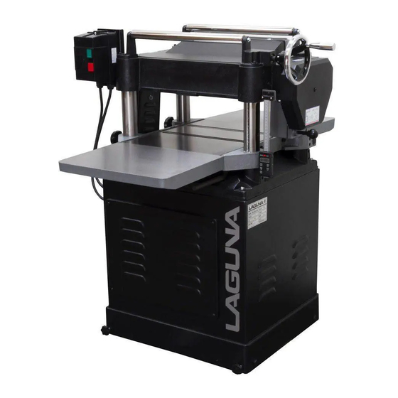
- Page 1 16” Planer with ShearTec II Manual LAGUNA TOOLS 2072 Alton Parkway Irvine, California 92606 Ph: 800.234.1976 Model Numbers: MPLAN1510-0120 www.lagunatools.com © 2017, Laguna Tools, Inc. LAGUNA® and the LAGUNA Logo® are the registered trademarks of Laguna Tools, Inc. All rights reserved.
-
Page 3: Table Of Contents
Table of contents Page number Safety Rules Warranty Noise emission Specification sheet Receiving your planer Introduction to your planer What you will receive with the planer Parts of the planer Where to locate your planer Unpacking your planer Assembly and setup Running and adjusting the planer Maintenance Troubleshooting... -
Page 4: Safety Rules
Safety Rules As with all machinery, there are certain hazards involved with the operation and use. Using it with caution will considerably lessen the possibility of personal injury. However, if normal safety precautions are overlooked or ignored, personal injury to the operator may result. If you have any questions relative to the installation and operation, do not use the equipment until you have contacted your supplying distributor. -
Page 5: Warranty
Machines sold through dealers must be registered with Laguna Tools within 30 days of purchase to be covered by this warranty. Laguna Tools guarantees all new machines and accessories sold to be free of manufacturers’... -
Page 6: Noise Emission
Ensure that there is no visible damage to the packing or the machine. You need to do this prior to the driver leaving. All damage must be noted on the delivery documents and signed by you and the delivery driver. You must then contact the seller (Laguna Tools) within 24 hours. - Page 7 Introduction to planers The planer is designed to give you years of safe service. Read this owner’s manual in its entirety before assembly or use. The planer is generally defined as a machine that cuts planks of wood smooth and parallel.
-
Page 8: What You Will Receive With The Planer
4. Guards. Guards are designed to reduce the risk of injury. Always use the guards. 5. Stock. Your safety will be greatly enhanced if you only use good lumber. Only work with lumber after you have inspected it completely. Staples, nails, loose knots and any other metal in the plank will damage your cutter head and could cause injury or fire. -
Page 9: Parts Of The Planer
Parts of the planer/moulder. The planer/moulder major parts are discussed in this manual. If you are not familiar with the planer/moulder, take the time to read this section and become familiar with the machine. 1. Body. The body is made from pressed steel and is designed to give the machine support and... - Page 10 Where to locate your machine. Before you remove your machine from the pallet, select the area where you will use your machine. There are no hard-and-fast rules for its location, but below are a few guidelines. 1. There should be an area at the front and back of the machine suitable for the length of wood that you will be machining.
-
Page 11: Assembly And Setup
Assembly and setup. Mobility kit. Mobility wheel Mobility clamp screw The mobility wheels come pre-fitted to the base of the machine. The wheels are locked by tightening the clamp screws on the outside of the body. Fitting the dust chute. Dust chute Upper fixing screws Lower fixing screws... - Page 12 Connecting the electrical supply. Note. A qualified electrician must carry out the installation. Power termination box Cover removed Ensure that the electrical supply corresponds with that of the machine (single-phase 220 V). It is recommended that you use a 30-amp mains breaker. The mains cable must be connected into the power termination box.
- Page 13 Fitting the vertical adjustment handle. Handle 1. Clean the shaft and the key. 2. Slide the handle onto the shaft. Ensure that the key lines up with the key way in the handle, and that the key is bottomed out in the shaft slot. You may have to gently tap the handle, as the key may be a tight fit.
- Page 14 3. Bring the extension table up level with the main table [check both sides of the table]. 4. By loosening one of the fixing bolts and tightening the jacking screw, the table can be jacked parallel with the main table. This process must be done slowly jacking a small amount each side so that no excessive strain is put on the table...
- Page 15 production. As the machine is used, some functions may move, and it is good practice to know the process for adjusting the machine prior to production. Test Run Now that the assembly is complete it is time to conduct a test run. During the test run you will check the following points.
- Page 16 To engage the power feed rollers, pull or push the power feed handle with the motor running. Pushing the handle in, selects 20 FPM and pulling it out selects 16 FPM. The centre position is neutral. Note. Only engage and disengage the power feed with the motor running. Adjusting the table height.
- Page 17 Adjusting the drive belts. Motor adjustor Cover removed The drive belts should be checked after running the machine for approximately 10 hours. The belts bed into the pulleys and will slacken off slightly. If they are not adjusted, slippage may accrue, and this will cause early belt failure. There should be approximately 3/16"...
- Page 18 1. With the power disconnected from the machine. Remove the cutter head cover, and the dust shute. 2 Loosen the tooth with the special allen key. 2. Lift the tooth and rotate to the new cutting face. Note. Take special care to clean the tooth and its mating surface.
-
Page 19: Maintenance
Maintenance. As with any machine, to ensure optimal performance, you must conduct regular maintenance. Daily checks. 1. Clean the machine and lubricate unpainted surfaces with a Teflon-based lubricant. Wipe off any excess and buff with a dry polishing cloth. This will reduce the likelihood of rust forming and reduce the friction on the tables as the wood is machined. - Page 20 1. Remove the side cover to access the motor. 2. Remove the belt guard to access the drive belts. 3. Loosen the motor adjustor nuts. 4. Remove the drive belts. 5. Fit the new belts. 6. Re-tension the belts by tightening the top motor adjusting nut. There should be a 3/16"...
- Page 21 Chain tension wheel Power drive cover removed 5. Remove the power drive cover. 6. Check that the chain tension wheel is free to move and that the chains are clean and lubricated. 7. Reassemble. Lubricating the machine. Lubrication oil to be added every 30 hours of operation, to both sets of holes as shown.
- Page 22 The drive roller, pressure roller and anti- kickback teeth come factory set but should adjustment be required proceed as follows. Loosen the lock nut and move the adjusting screw. Remember to tighten the lock nut once the adjustment has been completed. Note.
-
Page 23: Troubleshooting
Troubleshooting and fault finding. Problem Cause Corrective action Motor will not start or 1. Short circuit 2. Repair or replace short fuses or circuit breakers circuit item. blow. 2. Start capacitor faulty. 3. Fit new capacitor. 3. Motor thermal 4. Replace thermal protection circuit breaker protection circuit beaker faulty, or motor is at fault. - Page 24 Chipping or marks 1. Knots or conflicting 1. Inspect job for knots (consistent pattern). grain direction in wood. and grain direction; only use good material. 2. Nicked or chipped 2. Replace affected blades. blades. 3. Taking too of a deep 3.
- Page 25 Exploded view drawings...
- Page 29 PARTS LIST FOR MPLAN2010-0130 Part No. Descriptions Q'ty 230118-000 170871-000 BELT GUARD FRONT 014009-000 V-BELT 380147-901 BOLT 000003-204 HEX. SCREW M8*1.25P*20 006001-043 FLAT WASHER 8.2 *30*4.0t 000902-202 HEX SCREW W/WASHER M6*1.0P*12 170432-000 BELT GUARD REAR 009005-200 HEX NUT 5/16"-18NC 050273-901 CUTTERHEAD PULLEY 170488-000 DUST CHUTE...
- Page 30 050292-000 SIDE COVER 000104-112 SOC HD CAP SCREW M8*1.25P*40 280050-000 SPRING Part No. Descriptions Q'ty 170406-901 HOOK 170474-901 SHAFT 000103-110 SOC HD CAP SCREW M6*1.0P*35 170475-904 SIDE COVER GUARD 937574-000 MAGNETIC SWITCH ASSY 5HP.1PH 821007-030 MAGNETIC SWITCH 5HP.1PH 42.1 42.2 172507-904 SWITCH MOUNTING PLATE 003303-207...
- Page 31 210114-000 KNIFE 15*15*2.5t 280051-000 SPRING 130039-000 BUSHING 170408-902 RETAINER PLATE 006305-100 SPRING WASHER 8.2*15.4 170477-019 PRESSURE PLATE Part No. Descriptions Q'ty 360405-000 OUTFEED ROLLER 012003-008 5*5*22 070012-000 CHAIN SPROCKET 006001-020 FLAT WASHER 6.2*20*3.0t 000002-203 HEX. SCREW M6*1.0P*16 070016-025 BRACKET 360386-000 SHAFT 170478-019 CHIP BREAKER...
- Page 32 006002-046 FLAT WASHER 8.5*16*1.5t 320205-000 SHAFT 012004-003 6*6*40 012003-002 5*5*10 320198-000 GEAR 250372-615 KNOB 016304-000 CHAIN #06B*50P 150008-000 CHAIN SPROCKET 043401-000 PLUG PT1/4"-19牙 Part No. Descriptions Q'ty 043608-000 OIL SEAL TC28*40*8 050281-000 GEARBOX 340012-615 GEARBOX GASKET 922351-000 GEAR ASSEMBLY 010102-000 RETAINING RING RTW-32 360357-901...
- Page 33 000003-105 HEX. SCREW M8*1.25P*25 000204-105 SET SCREW M8*1.25P*20 000403-204 FLAT HEAD SCREW M6*1.0P*20 170479-000 STAND ACCESS PANEL 922874-000 STAND 006002-091 FLAT WASHER 13*28*3.0t 000005-202 HEX. SCREW M12*1.75P*50 050321-008 MOTOR PLATE 190074-901 SPACER 900755-000 MOTOR ASSY 5HP*230V*60HZ*1PH 138.1 593012-000 MOTOR 5HP*230V*60HZ*1PH 138.2 012202-002 5*5*30 Part No.
- Page 34 010006-000 RETAINING RING STW-15 000003-205 HEX. SCREW M8*1.25P*25 030305-000 BALL BEARING 6202Z(A) 010103-000 RETAINING RING RTW-35 150012-000 CHAIN SPROCKET 006001-078 FLAT WASHER 10.5*19*1.5t 008008-100 HEX NUT M10*1.25P 250173-000 EXPANSION BEND 001104-502 ROUND HEAD TAPPING SCREW M5*2.12P*10 170481-901 FIXING BUSH 050298-000 MAIN COLUMN 010202-000 RETAINING RING...
- Page 35 250402-000 WHEEL 009102-200 HEX NUT 3/8"-16NC 006002-077 FLAT WASHER 10.5*19*1.0t 921246-000 DIGITAL READ OUT 9 inch 208.1 921245-000 DIGITAL READ OUT 9 inch 208.2 171370-904 BRACKET 208.3 171371-904 BRACKET 208.4 000205-102 SET SCREW M10*1.5P*30 208.5 008007-100 HEX NUT M10*1.5P 208.6 006001-045 FLAT WASHER 8.5*16*1.0t 208.7 000104-110...
- Page 37 Laguna Tools MPLAN1510-0130: Platinum Series 16" Planer...
- Page 38 Dear Woodworker: Thank you for your purchase and welcome to the Laguna Tools group of discriminating woodworkers. I understand that you have a choice of where to purchase your machines and appreciate the confidence you have in our products. Every machine sold by Laguna Tools has been carefully designed and well thought through from a woodworker’s perspective.
-
Page 39: Introduction To Your Planer
Table of contents Page number Safety Rules Warranty Noise emission Specification sheet Receiving your planer Introduction to your planer What you will receive with the planer Parts of the planer Where to locate your planer Unpacking your planer Assembly and setup Running and adjusting the planer Maintenance Troubleshooting... - Page 40 Safety Rules As with all machinery, there are certain hazards involved with the operation and use. Using it with caution will considerably lessen the possibility of personal injury. However, if normal safety precautions are overlooked or ignored, personal injury to the operator may result. If you have any questions relative to the installation and operation, do not use the equipment until you have contacted your supplying distributor.
- Page 41 Inc., to be a manufacturer's defect. We require the defective item/part to be returned to Laguna Tools. In the event the item/part is determined to be damaged due to lack of maintenance, cleaning or misuse/abuse, the customer will be responsible for the cost to replace the item/part, plus all related shipping charges.
- Page 42 Ensure that there is no visible damage to the packing or the machine. You need to do this prior to the driver leaving. All damage must be noted on the delivery documents and signed by you and the delivery driver. You must then contact the seller (Laguna Tools) within 24 hours.
- Page 43 Introduction to planers The planer is designed to give you years of safe service. Read this owner’s manual in its entirety before assembly or use. The planer is generally defined as a machine that cuts planks of wood smooth and parallel.
- Page 44 4. Guards. Guards are designed to reduce the risk of injury. Always use the guards. 5. Stock. Your safety will be greatly enhanced if you only use good lumber. Only work with lumber after you have inspected it completely. Staples, nails, loose knots and any other metal in the plank will damage your cutter head and could cause injury or fire.
- Page 45 Parts of the planer/moulder. The planer/moulder major parts are discussed in this manual. If you are not familiar with the planer/moulder, take the time to read this section and become familiar with the machine. 1. Body. The body is made from pressed steel and is designed to give the machine support and...
- Page 46 Where to locate your machine. Before you remove your machine from the pallet, select the area where you will use your machine. There are no hard-and-fast rules for its location, but below are a few guidelines. 1. There should be an area at the front and back of the machine suitable for the length of wood that you will be machining.
- Page 47 Assembly and setup. Mobility kit. Mobility wheel Mobility clamp screw The mobility wheels come pre-fitted to the base of the machine. The wheels are locked by tightening the clamp screws on the outside of the body. Fitting the dust chute. Dust chute Upper fixing screws Lower fixing screws...
- Page 48 Connecting the electrical supply. Note. A qualified electrician must carry out the installation. Power termination box Cover removed Ensure that the electrical supply corresponds with that of the machine (single-phase 220 V). It is recommended that you use a 30-amp mains breaker. The mains cable must be connected into the power termination box.
- Page 49 Fitting the vertical adjustment handle. Handle 1. Clean the shaft and the key. 2. Slide the handle onto the shaft. Ensure that the key lines up with the key way in the handle, and that the key is bottomed out in the shaft slot. You may have to gently tap the handle, as the key may be a tight fit.
- Page 50 3. Bring the extension table up level with the main table [check both sides of the table]. 4. By loosening one of the fixing bolts and tightening the jacking screw, the table can be jacked parallel with the main table. This process must be done slowly jacking a small amount each side so that no excessive strain is put on the table...
- Page 51 production. As the machine is used, some functions may move, and it is good practice to know the process for adjusting the machine prior to production. Test Run Now that the assembly is complete it is time to conduct a test run. During the test run you will check the following points.
- Page 52 To engage the power feed rollers, pull or push the power feed handle with the motor running. Pushing the handle in, selects 20 FPM and pulling it out selects 16 FPM. The centre position is neutral. Note. Only engage and disengage the power feed with the motor running. Adjusting the table height.
- Page 53 Adjusting the drive belts. Motor adjustor Cover removed The drive belts should be checked after running the machine for approximately 10 hours. The belts bed into the pulleys and will slacken off slightly. If they are not adjusted, slippage may accrue, and this will cause early belt failure. There should be approximately 3/16"...
- Page 54 1. With the power disconnected from the machine. Remove the cutter head cover, and the dust shute. 2 Loosen the tooth with the special allen key. 2. Lift the tooth and rotate to the new cutting face. Note. Take special care to clean the tooth and its mating surface.
- Page 55 Maintenance. As with any machine, to ensure optimal performance, you must conduct regular maintenance. Daily checks. 1. Clean the machine and lubricate unpainted surfaces with a Teflon-based lubricant. Wipe off any excess and buff with a dry polishing cloth. This will reduce the likelihood of rust forming and reduce the friction on the tables as the wood is machined.
- Page 56 1. Remove the side cover to access the motor. 2. Remove the belt guard to access the drive belts. 3. Loosen the motor adjustor nuts. 4. Remove the drive belts. 5. Fit the new belts. 6. Re-tension the belts by tightening the top motor adjusting nut. There should be a 3/16"...
- Page 57 Chain tension wheel Power drive cover removed 5. Remove the power drive cover. 6. Check that the chain tension wheel is free to move and that the chains are clean and lubricated. 7. Reassemble. Lubricating the machine. Lubrication oil to be added every 30 hours of operation, to both sets of holes as shown.
- Page 58 The drive roller, pressure roller and anti- kickback teeth come factory set but should adjustment be required proceed as follows. Loosen the lock nut and move the adjusting screw. Remember to tighten the lock nut once the adjustment has been completed. Note.
- Page 59 Troubleshooting and fault finding. Problem Cause Corrective action Motor will not start or 1. Short circuit 2. Repair or replace short fuses or circuit breakers circuit item. blow. 2. Start capacitor faulty. 3. Fit new capacitor. 3. Motor thermal 4. Replace thermal protection circuit breaker protection circuit beaker faulty, or motor is at fault.
- Page 60 Chipping or marks 1. Knots or conflicting 1. Inspect job for knots (consistent pattern). grain direction in wood. and grain direction; only use good material. 2. Nicked or chipped 2. Replace affected blades. blades. 3. Taking too of a deep 3.
- Page 61 Exploded view drawings...
- Page 65 PARTS LIST FOR MPLAN2010-0130 Part No. Descriptions Q'ty 230118-000 170871-000 BELT GUARD FRONT 014009-000 V-BELT 380147-901 BOLT 000003-204 HEX. SCREW M8*1.25P*20 006001-043 FLAT WASHER 8.2 *30*4.0t 000902-202 HEX SCREW W/WASHER M6*1.0P*12 170432-000 BELT GUARD REAR 009005-200 HEX NUT 5/16"-18NC 050273-901 CUTTERHEAD PULLEY 170488-000 DUST CHUTE...
- Page 66 050292-000 SIDE COVER 000104-112 SOC HD CAP SCREW M8*1.25P*40 280050-000 SPRING Part No. Descriptions Q'ty 170406-901 HOOK 170474-901 SHAFT 000103-110 SOC HD CAP SCREW M6*1.0P*35 170475-904 SIDE COVER GUARD 937574-000 MAGNETIC SWITCH ASSY 5HP.1PH 821007-030 MAGNETIC SWITCH 5HP.1PH 42.1 42.2 172507-904 SWITCH MOUNTING PLATE 003303-207...
- Page 67 210114-000 KNIFE 15*15*2.5t 280051-000 SPRING 130039-000 BUSHING 170408-902 RETAINER PLATE 006305-100 SPRING WASHER 8.2*15.4 170477-019 PRESSURE PLATE Part No. Descriptions Q'ty 360405-000 OUTFEED ROLLER 012003-008 5*5*22 070012-000 CHAIN SPROCKET 006001-020 FLAT WASHER 6.2*20*3.0t 000002-203 HEX. SCREW M6*1.0P*16 070016-025 BRACKET 360386-000 SHAFT 170478-019 CHIP BREAKER...
- Page 68 006002-046 FLAT WASHER 8.5*16*1.5t 320205-000 SHAFT 012004-003 6*6*40 012003-002 5*5*10 320198-000 GEAR 250372-615 KNOB 016304-000 CHAIN #06B*50P 150008-000 CHAIN SPROCKET 043401-000 PLUG PT1/4"-19牙 Part No. Descriptions Q'ty 043608-000 OIL SEAL TC28*40*8 050281-000 GEARBOX 340012-615 GEARBOX GASKET 922351-000 GEAR ASSEMBLY 010102-000 RETAINING RING RTW-32 360357-901...
- Page 69 000003-105 HEX. SCREW M8*1.25P*25 000204-105 SET SCREW M8*1.25P*20 000403-204 FLAT HEAD SCREW M6*1.0P*20 170479-000 STAND ACCESS PANEL 922874-000 STAND 006002-091 FLAT WASHER 13*28*3.0t 000005-202 HEX. SCREW M12*1.75P*50 050321-008 MOTOR PLATE 190074-901 SPACER 900755-000 MOTOR ASSY 5HP*230V*60HZ*1PH 138.1 593012-000 MOTOR 5HP*230V*60HZ*1PH 138.2 012202-002 5*5*30 Part No.
- Page 70 010006-000 RETAINING RING STW-15 000003-205 HEX. SCREW M8*1.25P*25 030305-000 BALL BEARING 6202Z(A) 010103-000 RETAINING RING RTW-35 150012-000 CHAIN SPROCKET 006001-078 FLAT WASHER 10.5*19*1.5t 008008-100 HEX NUT M10*1.25P 250173-000 EXPANSION BEND 001104-502 ROUND HEAD TAPPING SCREW M5*2.12P*10 170481-901 FIXING BUSH 050298-000 MAIN COLUMN 010202-000 RETAINING RING...
- Page 71 250402-000 WHEEL 009102-200 HEX NUT 3/8"-16NC 006002-077 FLAT WASHER 10.5*19*1.0t 921246-000 DIGITAL READ OUT 9 inch 208.1 921245-000 DIGITAL READ OUT 9 inch 208.2 171370-904 BRACKET 208.3 171371-904 BRACKET 208.4 000205-102 SET SCREW M10*1.5P*30 208.5 008007-100 HEX NUT M10*1.5P 208.6 006001-045 FLAT WASHER 8.5*16*1.0t 208.7 000104-110...
- Page 72 Laguna Tools is not responsible for errors or omissions. Specifications subject to change. Machines may be shown with optional accessories. © 2017, Laguna Tools, Inc. LAGUNA® and the LAGUNA Logo® are the registered trademarks of Laguna Tools, Inc. All rights reserved.
Need help?
Do you have a question about the MPLAN1510-0120 and is the answer not in the manual?
Questions and answers