Table of Contents
Advertisement
Quick Links
Advertisement
Table of Contents

Related Manuals for Laguna Tools Tools-PX-22 SHEARTEC II


Summary of Contents for Laguna Tools Tools-PX-22 SHEARTEC II
- Page 2 Table of Contents- Dealer Machinery Warranty- Pg. 4. Contant Information/Customer Service-Pg. 5. Safety Protocols-Pg.6-10. Electrical Safety-Pg. 11-17. Specifications of the PX-22- Pg. 18. Machine Overview- Pg.19-22. Set-Up Machine (MUST READ)- Pg.23. Placement Of Machine & Unboxing- Pg. 24-26. Tool Inventory List- Pg. 27. Assembling- Pg.
- Page 3 Thank you for investing in a PX-22 Planer by Laguna Tools. This planer is one of a family of unique machines proudly offered by Laguna Tools. Every Laguna machine is engineered for years of dependable service. Please feel free to contact Laguna Tools if you have a question or suggestion.
- Page 4 New woodworking machines sold by Laguna Tools carry a two-year warranty effective from the date of dealer invoice to consumer. Machines sold through dealers must be registered with Laguna Tools within 30 days of purchase to be covered by this warranty. Laguna Tools guarantees all new machine sold to be free of manufacturers’ defective workmanship, parts, and materials.
- Page 5 For immediate service on any Laguna Tools products: +1 (800) 234-1976 customerservice@lagunatools.com Laguna Tools, Inc. LAGUNA® and the LAGUNA Logo® are the registered trademarks of Laguna Tools, Inc. All rights reserved. 12/01/2021 LAGUNA AMERICAN HEADQUARTERS Texas: 744 Refuge Way Suite 200, Grand Prairie, Texas 75050, U.S.A.
- Page 6 Safety Protocols- Read and understand all warnings and operation instructions before using any tool or equipment. Always follow basic safety precautions to reduce the risk of personal injury. Improper operation, maintenance or modification of tools or equipment could result in serious injury and property damage.
- Page 7 Safety Protocols-...
- Page 8 Safety Protocols (Cont’d.)-...
- Page 9 Safety Protocols (Cont’d.)-...
- Page 10 Safety Protocols (Cont’d.)- LIKE ALL MACHINES, THERE IS DANGER ASSOCIATED WITH THE MACHINE. INJURY IS FREQUENTLY CAUSED BY LACK OF KNOWLEDGE OR FAMILIARITY. USE THIS MACHINE WITH RESPECT. IF NORMAL SAFETY PRECAUTIONS ARE OVERLOOKED OR IGNORED, SERIOUS PERSONAL INJURY MAY OCCUR. 1.
- Page 11 Electrical Cord and Plug is not provided with Ordered Machine. Electrical Safety- Make sure to follow Electrical Installation stated in the instructions below. Power Supply A separate electrical circuit should be used for each machine. This circuit should not be less than the wiring listed below and should be protected with an appropriate circuit breaker based on the total running and start-up amperage's (listed below).
- Page 12 A Electrical Cord and Plug is not provided with Ordered Electrical Safety (Cont’d.)- Machine. Make sure to follow Electrical Installation stated in the instructions below. If this information is different than what is stated on the Motor Specification Plate - omit this information.
-
Page 13: Grounding Methods
A Electrical Cord and Plug is not provided with Ordered Electrical Safety (Cont’d.)- Machine. Make sure to follow Electrical Installation stated in the instructions below. *Electrical Code that must be met in your local state (USA) or province (CSA). Grounding Methods- Electrical Cord and Plug is not provided with Ordered Machine. - Page 14 Electrical Safety (Cont’d.)- 1.) All Grounded, Cord-Connected Machines: In the event of a malfunction or breakdown, grounding provides a path of least resistance for electric current to reduce the risk of electric shock. This tool is equipped with an electric cord having an equipment grounding conductor and a grounding plug.
- Page 15 Electrical Safety (Cont’d.)- 2.) Grounded, cord-connected machines intended for use on a supply circuit having a nominal rating less than 150 volts: This tool is intended for use on a circuit that has an outlet that looks like the one illustrated in Fig.
- Page 16 Electrical Safety (Cont’d.)- 3.) Grounded, Cord-Connected tools intended for use on a supply circuit having a nominal rating between 150 – 250 volts, inclusive: This tool is intended for use on a circuit that has an outlet that looks like the one illustrated in Fig.
- Page 17 Extension Cords- Warning: EXTENSION CORDS ARE NOT RECOMMENDED. If the customer needs to use an extension cord, the Extension Cord must be qualified to fall within Local Electrical Code (USA, CSA, etc.). If the customer utilizes an Extension Cord that does not fall within Code and causes damage to machine, the Warranty will be Voided.
- Page 18 Specifications for the PX-22 SHEARTEC II Planer-...
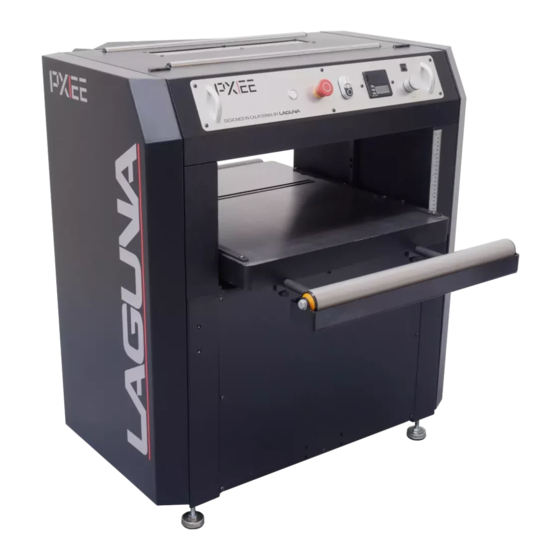
- Page 19 Machine Overview- PX-22 Shear-Tec: II Planer- Control Panel Stock Return Rollers. (2) Emergency Stop (Limiter) Min. Stop Block (1/16”) Table Roller Feed Speed Controller Table Table Height Adjustment Table Extension Roller Qty. (2) Loading Hook Loading Hook Leveling Feet (Qty. 4) The Limiter: Acts as a stop to prevent the cutterhead from contacting the table and to prevent stock from sliding past the edge of the cutterhead.
- Page 20 Machine Overview (Cont’d.)- Front of PX-22 Shear-Tec: II Planer Thickness Gauge Rear of PX-22 Shear-Tec: II Planer Dust Chute Hood Latches Hood Latches Table Table Roller Table Extension Roller Table Roller Table Extension Roller Table Loading Hook Feed Speed Control Machine Information Tag Table Height Adjustment...
- Page 21 Machine Overview (Cont’d.)- Front Control Panel-Main Components of PX22- A.) “On” Light Indicator. Emergency Stop (E-STOP): Stops all functions of machine, however, power continues to machine. NOTICE! To reset E-STOP, rotate switch clockwise until the button “pops” out. C.) “ON/OFF” Switch: Starts and Stops rotation of cutterhead. NOTICE! The Planer will not work if the E-STOP is engaged or if the Hood is Open.
- Page 22 Machine Overview (Cont’d.)- Limiter: The Limiter: Acts as a stop to prevent the cutterhead from contacting the table and to prevent stock from sliding past the edge of the cutterhead. Table Roller: The Roller facilitates movement of the Work Piece across the Table. Extension Rollers: Adjustable Rollers that extend for increased workpiece support.
- Page 23 Setup Machine **(MUST READ)**- Setup Overview (MUST READ)- When setting up your PX-22 Shear-Tec: II Planer, please take a moment to read this overview prior to starting. The machine comes mostly assembled. You will have to assemble the leveling feet, the dust chute, and calibrate the height.
- Page 24 • ALL SHIPPING DAMAGE MUST BE NOTED UPON DELIVERY AND SIGNED BY THE OWNER AND THE DELIVERY DRIVER. IF YOU FIND ANY DAMAGED ITEMS IN YOUR PACKAGE, YOU MUST CONTACT LAGUNA TOOLS TO FILE A COMPLAINT. IN ORDER TO RETURN DAMAGED GOODS UNDER THE LIMITED WARRANTY TO LAGUNA TOOLS, INC., YOU MUST HAVE THE ORIGINAL PACKAGING.
- Page 25 Placement- Before you remove your machine from the packaging, select the area where you will use your machine. There are no hard and fast rules for its location, but below are a few guidelines: 1.) There should be sufficient area at the front of the machine to allow you to work on it comfortably.
- Page 26 Unboxing- WARNING! • THE MACHINE WEIGHS 865 LBS (393 KG). ENSURE THAT YOU HAVE ENOUGH PEOPLE TO DO THE JOB SAFELY. • IF YOU HAVE ANY DOUBT ABOUT THE DESCRIBED PROCEDURE, SEEK PROFESSIONAL ASSISTANCE. DO NOT ATTEMPT ANY PROCEDURE THAT YOU FEEL IS UNSAFE, OR THAT YOU DO NOT HAVE THE PHYSICAL CAPABILITY OF ACHIEVING.
- Page 27 Tool Inventory List- The following depicts items shipped with your machine. Before assembling, ensure that you have received all parts shown below. Machine parts should arrive sealed in plastic bags. Remove parts from plastic bags before laying them out to inventory them. Tools/items Required: Assembly &...
-
Page 28: Leveling Feet
Assembling- Machine Preparation and Setup: 1.) Level machine using the four leveling feet on each of the four corners. Lock leveling feet into position with the nut on the leveling foot stud. LEVELING FEET... -
Page 29: Caster Installation
(OPTIONAL) If Installing Universal Casters- Installing Universal Caster Set- Pt. #TH0540-001/Laguna Part #: UNIJPWS21: Pt#TH0540-001/ Laguna Part #: UNIJPWS21 Pt#TH0540-001/ Laguna Part #: UNIJPWS21 CASTER INSTALLATION 1.) Raise and block planer for attaching caster set. 2.) Assemble swivel caster into swivel caster bracket (straight bracket) by placing bolt #5 through bracket and caster and securing with lock nut #4. Then place bolt #6 down through bracket into caster mount. - Page 30 Assembling (Cont’d.)- Machine Preparation and Setup: 1) Make sure to use Proper PPE (Heavy Leather or Kevlar Gloves) when changing Blades on Blade Roller to prevent injury: 2.) Clean all rust protected surfaces with a commercial de-greaser. DO NOT use acetone, gasoline, lacquer thinner or any type of cleaner that could damage paint.
- Page 31 4a.) Table Bottom Roller Adjustment (Cont’d.): 2.) Turn the knobs (See Figure G) to move the table roller up or down to the desired position, then secure Bottom Roller in position. 4b.) Top Roller Adjustment Procedure (Cont’d.)- 1.) When appropriate level is reached, on the Table Height Adjustment Wheel side, open or remove the Panel Cover, just below the main Top Roller Axel (Figure H) there is Adjustment Bolt to adjust the height and the Hex Nut, tighten to secure and lock height of the Top Roller.
- Page 32 4c.) To Adjust Pressure & replace the pressure Springs for the Top Roller- 1.) On the Top of the exposed Carbide Blade Roller area, locate 4 large Allen Set Screws on the Corners of the Planer (See Figure J), to adjust the amount of pressure (Increase/Decrease) on the Top Roller, use appropriate T-Wrench as pictured below.
- Page 33 4d.) To remove the 4-Internal 7-Coil Springs that adjusts the pressure of the Top roller, locate 4-Large Allen Set Screws on the Corners of the Planer, to remove these use appropriate T-Wrench as pictured below. Remove Allen Set Screws completely, remove the 7-Coil Springs then replace Springs.
- Page 34 Assembling (Cont’d.)- Machine Preparation and Setup: 5.) The Dust Chute can be attached with the port facing either to the right or left. To attach use 4-four included screws (Fig. H) to mount to the rear (outfeed) side of the planer head. NOTICE-, MAKE SURE THE DUST COLLECTION SYSTEM HAS SUFFICIENT CAPACITY AND CFM FOR THIS PLANER.
- Page 35 Power Supply Circuit Requirements- The power source circuit for your machine must be grounded and rated for the amperage given below. Never replace a circuit breaker on an existing circuit with one of higher amperage without consulting a qualified electrician to ensure compliance with wiring codes. If you are unsure about the wiring codes in your area or plan to connect your machine to a shared circuit, consult a qualified electrician.
- Page 36 Motor Specifications (Cont’d.)- WARNING!- WHEN COMPLETED, THE MACHINE MUST CONFORM TO THE NATIONAL ELECTRIC CODE AND ALL LOCAL CODES AND ORDINANCES. Connecting Power (See also Wiring Diagram page XX)- 1. Remove screws securing cover to connection box. 2. Insert power cable through strain relief, tighten cinch nut and attach wires to terminals. 3.
-
Page 37: Thickness Scale Calibration
Calibrating the Thickness Scale- NOTICE!-The following procedures describe the use of a “Calibrating Board.” It is a piece of hardwood which has been surfaced on one side with a jointer, drum sander or wide belt sander. With the Planer “OFF”- •... - Page 38 Calibrating the Thickness Scale (Cont’d.)- THICKNESS SCALE CALIBRATION 1.) Use the Table Height Adjustment handle (Fig. A) to raise the table until the infeed roller is “approximately 1/16” above the calibrating board. 2.) Remove the calibrating board from the planer. 3.) Connect power to the planer and turn “ON.”...
- Page 39 Calibrating the DRO (Digital Read Out)- 1.) Remove the battery cover of the DRO and install (2) AAA batteries. DRO Button Reference and Use It is helpful to DRO BATTERIES familiarize these buttons and their purpose with the Wixey™ DRO. DRO (Digital Read Out) ADJUSTMENT...
-
Page 40: Operation
Operation- CAUTION!-PLACE THE PLANER ON A “SECURE AND STABLE SURFACE” FOR OPERATION.“CLAMP OR BOLT” THE PLANER INTO POSITION. 1.) Establish the proper depth of cut (Equal to or less than 1/16”), using either the DRO (Digital Read Out) or Scale. 2.) Pull out and lock each extension roller to support long stock. - Page 41 Operation (Cont’d.)- 6.) Feed stock into planer, maintain control and support of stock until the stock is securely feeding through planer. 7.) Reposition yourself to the outfeed side of planer and control and support stock until it has exited the outfeed roller. Helpful Tips- •...
-
Page 42: Maintenance
Maintenance- CAUTION!-FAILURE TO MAINTAIN THIS MACHINE USING REQUIRED ROUTINE UPKEEP, SAFEGUARDING & PREVENTIVE MEASURES WILL VOID WARRANTY. General Keep your machine clean. At the end of each day, clean the machine. Wood contains moisture, and if sawdust or wood chips are not removed they will cause rust. In general, we recommend that you only use a Teflon-based lubricant on the planer. - Page 43 Shear-Tec II Knife Rotation/Replacement- CAUTION!- KNIFE INSERTS ARE DANGEROUSLY SHARP. USE EXTREME CAUTION WHEN INSPECTING, REMOVING, OR REPLACING KNIFE INSERTS. WARNING!- • TURN PLANER OFF AND DISCONNECT POWER BEFORE PERFORMING ANY MAINTENANCE OR ADJUSTMENTS! • MAKE SURE ALL KNIFE INSERT SCREWS ARE TIGHTENED SECURELY. LOOSE INSERTS CAN BE PROPELLED AT HIGH SPEED FROM A ROTATING CUTTERHEAD, CAUSING INJURY.
- Page 44 Shear-Tec II Knife Rotation/Replacement (Cont’d.)- It is advisable to rotate all inserts at the same time to maintain consistent cutting. However, if one or more knife inserts develops a nick, rotate only those inserts that are affected. Each knife insert has an etched reference mark so you can keep track of the rotation.
- Page 45 PX-22 (22”) Planer Front/Rear Precision Adjustment SOP-...
- Page 46 PX-22 (22”) Planer Front/Rear Precision Adjustment SOP (Cont’d.)-...
- Page 47 PX-22 (22”) Planer Front/Rear Precision Adjustment SOP (Cont’d.)-...
- Page 48 PX-22 (22”) Planer Front/Rear Precision Adjustment SOP (Cont’d.)-...
- Page 49 PX-22 (22”) Planer Front/Rear Precision Adjustment SOP (Cont’d.)-...
- Page 50 PX-22 (22”) Planer Front/Rear Precision Adjustment SOP (Cont’d.)-...
- Page 51 PX-22 (22”) Planer Front/Rear Precision Adjustment SOP (Cont’d.)-...
- Page 52 PX-22 (22”) Planer Front/Rear Precision Adjustment SOP (Cont’d.)-...
- Page 53 PX-22 (22”) Planer Front/Rear Precision Adjustment SOP (Cont’d.)-...
- Page 54 PX-22 (22”) Planer Front/Rear Precision Adjustment SOP (Cont’d.)-...
- Page 55 PX-22 (22”) Planer Front/Rear Precision Adjustment SOP (Cont’d.)-...
- Page 56 PX-22 (22”) Planer Front/Rear Precision Adjustment SOP (Cont’d.)-...
- Page 57 PX-22 (22”) Planer Front/Rear Precision Adjustment SOP (Cont’d.)-...
- Page 58 Poly-V-Belt Adjustment- WARNING! • TURN PLANER OFF AND DISCONNECT POWER BEFORE PERFORMING ANY MAINTENANCE OR ADJUSTMENTS! Poly-V-Belt (Fig. 1) tension has been set at the factory. If the belt has stretched and needs adjustment. 1.) Disconnect machine from power source. 2.) Open lower rear, and lower left-hand side panels.
- Page 59 Lubrication- Regular monitoring and replacement of lubrication is needed-...
- Page 60 Lubrication (Cont’d.)- The lubricant in the gear box must be drained and replaced every 2,500 hours. Multi-purpose gear box lubricant (#80 Weight Oil) will be suitable. To Replace the lubricant (Oil Drain Procedure): 1.) Remove the Lower Gear Box Oil Drain Plug (See A-Pt.
- Page 61 Lubrication (Cont’d.)- • The Gear Box Oil must be changed after 2500 hours of work (Instructions to remove Gear Box Oil Cover is as follows). Gear Box...
- Page 62 Lubrication (Cont’d.)- (Instructions on how to remove Gear Box Oil Cover & change Inner Gears is as follows-Cont’d.) Tools to Use- M6 Wrench. 1.) Safety-Shut Down all Power to PX-22 Planer, Pull Electrical Plug from Outlet. 2.) Remove the Right-Side Cover (Pt.# 172) of the Machine. 3.) Perform Oil Drain Procedure (See Page #61).
-
Page 63: Troubleshooting
Troubleshooting-... - Page 64 Wiring- WARNING!- REVIEW ELECTRICAL SAFETY (Pg’s.#6-16) PRIOR TO ANY WIRING PROCEDURES.
-
Page 65: Wiring-Diagram (1Ph)
Wiring-Diagram (1PH):... -
Page 66: Wiring-Diagram (3Ph)
Wiring-Diagram (3PH):... - Page 67 Replacement Parts Diagram- Cutterhead & Drivetrain -...
- Page 68 Replacement Parts Diagram- Table & Lift-...
- Page 69 Replacement Parts Diagram- Stand & Motor-...
-
Page 70: Replacement Parts Table
Replacement Parts Table-... - Page 71 Replacement Parts Table (Cont’d.) -...
- Page 72 Replacement Parts Table (Cont’d.) -...
- Page 73 Replacement Parts Table (Cont’d.) -...
- Page 74 Replacement Parts Table (Cont’d.) -...
- Page 75 Replacement Parts Table (Cont’d.) -...
- Page 76 Replacement Parts Table (Cont’d.) –...
- Page 77 Replacement Parts Table (Cont’d.)-...
-
Page 78: Warranty
Warranty-... -
Page 79: Manual Revision Record
Manual Revision Record Engineering/Design Change Date of Change Revision# Description 1/24/2022 New Proposed Manual for the PX-22 Shear-Tec II Planer. Added quantity of Oil 400 ml or 13.5 fl. oz. Removed Gage 1/27/2022 Block step. Changed Table of Contents. Page 38-Step 4-Restated: Removed Carraige Lock statement. 2/08/2022 Page 52-Step 8-Restated: Removed Dial Indicator custom made &... - Page 80 NOTES-...
Need help?
Do you have a question about the Tools-PX-22 SHEARTEC II and is the answer not in the manual?
Questions and answers