Table of Contents
Advertisement
Quick Links
Advertisement
Table of Contents

Related Manuals for Laguna Tools MPL1301-0130


Summary of Contents for Laguna Tools MPL1301-0130
- Page 1 13" Moulder Planer Manual LAGUNA TOOLS 2072 Alton Parkway Irvine, California 92606 Ph: 800.234.1976 Model Numbers: MPL1301-0130 www.lagunatools.com © 2018, Laguna Tools, Inc. LAGUNA® and the LAGUNA Logo® are the registered trademarks of Laguna Tools, Inc. All rights reserved.
-
Page 3: Table Of Contents
Table of contents Page number Safety Rules Warranty Noise emission Specification sheet Receiving your planer Introduction to your planer What you will receive with the planer Parts of the planer Where to locate your planer Unpacking your planer Assembly and setup Running and adjusting the planer Maintenance Troubleshooting... -
Page 4: Safety Rules
Safety Rules As with all machinery, there are certain hazards involved with the operation and use. Using it with caution will considerably lessen the possibility of personal injury. However, if normal safety precautions are overlooked or ignored, personal injury to the operator may result. If you have any questions relative to the installation and operation, do not use the equipment until you have contacted your supplying distributor. -
Page 5: Warranty
Machines sold through dealers must be registered with Laguna Tools within 30 days of purchase to be covered by this warranty. Laguna Tools guarantees all new machines and accessories sold to be free of manufacturers’... -
Page 6: Noise Emission
Noise emission. Notes concerning noise emission Given that there exists a relationship between noise level and exposure times, it is not precise enough to determine the need for supplementary precautions. The factors affecting the true level of exposure to operators are clearly the amount of time exposed, the characteristics of working environment, other sources of dust and noise, etc. -
Page 7: Receiving Your Planer
All damage must be noted on the delivery documents and signed by you and the delivery driver. You must then contact the seller (Laguna Tools) within 24 hours. Introduction to planer/moulders. The planer/moulder is designed to give you years of safe service. Read this owner’s manual in its entirety before assembly or use. -
Page 8: What You Will Receive With The Planer
What you will receive with the planer. 1. Roller support plates. 2. Guides. 3. Rollers. 4. Dust chute. 5. Leveling feet. 6. Gear box handle. 7. Gibs. 8. Screws. 9. Guide support rod. 10. Handles. -
Page 9: Parts Of The Planer
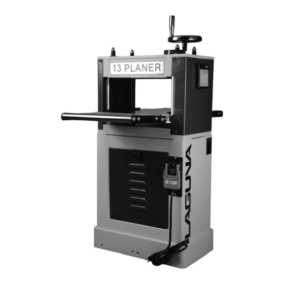
Parts of the planer/moulder. -
Page 10: Where To Locate Your Planer
The planer/moulder major parts are discussed in this manual. If you are not familiar with the planer/moulder, take the time to read this section and become familiar with the machine. 1. Body. The body is made from pressed steel and is designed to give the machine support and rigidity. -
Page 11: Unpacking Your Planer
4. Close to power source and dust collection. Unpacking your machine. Box removed Boxed machine Pallet securing bolts Side panel removed, parts inside To unpack your machine, you will need tin snips, knife and a wrench. -
Page 12: Assembly And Setup
1. Using the tin snips, cut the banding that is securing the machine to the pallet (if fitted). WARNING: EXTREME CAUTION MUST BE USED BECAUSE THE BANDING WILL SPRING AND COULD CAUSE INJURY. 2. Lift the box off and discard. 3. - Page 13 Fitting the support rollers. Support roller Support roller plates 1. Attach the support roller plates to the side of the table, both in- and out-feed sides. Do not fully tighten. 2. Fit the support rollers to both in- and out-feed sides of the machine.
- Page 14 Fitting the gear box engage/disengage handle. Screw on the gear box handle and tighten the lock nuts. Fitting the guides. Gear engage/disengage handle Guides Guide support shaft Fit the guide support shaft to the in- and out-feed sides of the machine. Attach the guides and secure with the clamping screw knobs.
- Page 15 Note. The dust chute has to be removed to access the cutter head. Attach the dust chute with the upper and lower fixing screws. Connecting the electrical supply. Note. A qualified electrician must carry out the installation. Ensure that the electrical supply corresponds with that of the machine (single-phase 220 V).
-
Page 16: Running And Adjusting The Planer
Running and adjusting the machine. Changing the cutter blades. Chip breaker Cutter head jacking screw Disconnect the power from the machine. Never conduct any maintenance or fitting of cutters with the power connected to the machine. 1. Remove the cover and the dust hood. 2. - Page 17 4. The blade will probably also be stuck against the cutter head. If the blade will not easily slide vertically, loosen by prying sideways as shown with a screwdriver. Care must be taken not to damage the blade or yourself while extracting the blades. 5.
- Page 18 Fitting moulder blades. Disconnect the power from the machine and never conduct any maintenance or fitting of cutters with the power connected to the machine. The moulder blades are fitted into the same slots in the cutter head as the planer blades.
- Page 19 3. Loosen the guide and move to align the job with the cutter head and clamp. 4. Bring the other guide up against the job and clamp in position. 5. Check that the job moves freely without excessive clearance. Test Run. Now that the assembly is complete, it is time to conduct a test run.
- Page 20 Adjusting the planer/moulder table height. Table height adjustment handle Height scale Height pointer Move the table to the thickness that you require. Note. Until you get experience with the machine, it is suggested that after setting the table thickness you machine a scrap piece of wood and check that the thickness is correct before you machine your production.
- Page 21 Adjusting the feed rollers. The table rollers come factory set 1/8" below the cutter head to suit the planer function. When moulding, the feed rollers have to be adjusted to suit the job. It is not possible to be accurate in determining the feed roller height, as this will depend on the profile that is being used.
- Page 22 Adjusting the table parallel to the cutter head. Chain tension bracket Sprocket The table is factory set parallel to the cutter head and should not need adjustment. If the machine is producing a tapered cut, adjustment can be made as follows. Disconnect the power from the machine.
-
Page 23: Maintenance
Installing a bed board. Certain operations require that the cutter cuts through the job. This will require that you make and fit a board to the table of the machine. Four holes are provided in the table to attach a board. The dimensions of the board are not important, but it is suggested that the board is 12 3/8"... -
Page 24: Troubleshooting
2. Loosen the motor clamping nuts as detailed earlier in the manual. 3. Remove the drive belts. 4. Fit the new belts. 5. Re-tension the belts. There should be a 3/16" deflection when the belt is pressed with moderate finger pressure. Tighten the motor clamping nuts. 6. - Page 25 care to make sure that all the cooling fins are clean. 4. Short circuit in motor 4. Repair or replace or loose connections. motor or loose connections. Cutter head slows or belt 1. V-belts loose. 1. Tighten V-belts. squeals when cutting. 2.
- Page 26 tension. Torn grain. 1. Cut too deep. 1. Reduce cut. 2. Cutting against the 2. Cut with the grain. grain. 3. Dull blades. 3. Replace the blades. Poor feeding of job. 1. Low feed roller 1. Reset feed rollers. pressure. 2.
-
Page 27: Electrical Drawing
Electrical drawing. -
Page 28: Exploded View Drawings And Parts Lists
Exploded view drawings. - Page 31 Copyright 2010 Laguna Tools, Inc ** Warning – no portion of these materials may be reproduced without written approval from Laguna Tools, Inc. All documentation subject to change without notice...
- Page 32 Laguna Tools is not responsible for errors or omissions. Specifications subject to change. Machines may be shown with optional accessories. © 2018, Laguna Tools, Inc. LAGUNA® and the LAGUNA Logo® are the registered trademarks of Laguna Tools, Inc. All rights reserved.
Need help?
Do you have a question about the MPL1301-0130 and is the answer not in the manual?
Questions and answers