Table of Contents
Advertisement
Quick Links
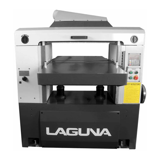
Industrial 25" Planer
Manual
LAGUNA TOOLS
2072 Alton Parkway
Irvine, California 92606
Ph: 800.234.1976
www.lagunatools.com
© 2018, Laguna Tools, Inc. LAGUNA® and the LAGUNA Logo® are the registered trademarks of Laguna Tools, Inc. All rights reserved.
Model Numbers: MPLAN25-10-1-0130
MPLAN25-15-3-0130
Advertisement
Table of Contents

Related Manuals for Laguna Tools MPLAN25-10-1-0130


Summary of Contents for Laguna Tools MPLAN25-10-1-0130
- Page 1 Industrial 25” Planer Manual LAGUNA TOOLS 2072 Alton Parkway Irvine, California 92606 Model Numbers: MPLAN25-10-1-0130 Ph: 800.234.1976 MPLAN25-15-3-0130 www.lagunatools.com © 2018, Laguna Tools, Inc. LAGUNA® and the LAGUNA Logo® are the registered trademarks of Laguna Tools, Inc. All rights reserved.
-
Page 2: Safty Rule
WARNING Read this manual completely and observe all warning labels on the machine. Every attempt to provide a safe, reliable, easy-to-use piece of machinery. Safety, however, is ultimately the responsibility of the individual machine operator. As with any piece of machinery, the operator must exercise caution, patience, and common sense to safely run the machine. - Page 3 11. Before performing any service, maintenance, adjustments or when changing knives disconnect the machine from power source. A machine under repair should be RED TAGGED to show it should not be used until the maintenance is complete. 12. Do not plane boards with loose knots, nails or any foreign material in the workpiece. Irregular, or warped stock should be jointed first on one side before planing a parallel surface.
-
Page 4: Table Of Contents
Table of Contents Page Safty Rule ..........................1 Uncrating the Machine ......................4 Machine Preparation and Setup ....................4 Dust Chute Assembly ......................5 Table Roller Handle Assembly ....................5 Control Panel ........................... 5 Digital Controller ........................5 Changing Units of Measure ..................... 6 Calibrating the Display ...................... -
Page 5: Uncrating The Machine
Uncrating the Machine Retain all packaging materials in case it becomes necessary to ship the machine to another site. Machine Preparation and Setup WARNING! The equipment used to lift this machine must have a rated capacity at, or above the weight of the planer. -
Page 6: Dust Chute Assembly
Dust Chute Assembly Mount the dust chute to the planer hood with eight M6x10 hex head screws B. Make sure the dust collection system has sufficient capacity and suction for your planer. Always turn on the dust collection system before starting the planer. -
Page 7: Changing Units Of Measure
Changing Units of Measure Press unit button A (Fig. 5) to toggle back and forth between inches and millimeters. Calibrating the Display The following sections will describe the use of a calibrating board. The calibrating board should be made of a hardwood and have one side that has been run through a jointer. -
Page 8: Raising And Lowering Table
Raising and Lowering Table Turn the handwheel A (Fig. 7) clockwise to raise the table. One revolution equals 1/32” or 0.03”. Note: The handwheel is spring loaded. Push in on the handwheel and rotate until the pins engage the detents. Adjusting Thickness Scale 1. -
Page 9: Sheartec Ii Cutterhead
ShearTec II CUTTERHEAD Knife inserts are dangerously sharp. Use extreme caution when inspecting, removing, or replacing knife inserts. The knife inserts on the 25” Planer are four-sided. When dull, simply remove each insert, rotate it 90° for a fresh edge, and re-install it. No further adjustment is necessary. -
Page 10: Setup Of Feed Rollers, Chip Breaker And
Setup of Feed Rollers, Chip Breaker and Pressure Bar WARNING! Disconnect machine from the power source before performing any adjustments or maintenance. Failure to comply may cause serious injury! The planer comes set up from the factory and shouldn’t need any adjustment. If you find adjustment is necessary, follow the below listed sections for setting the infeed roller, chip breaker, pressure bar... -
Page 11: Anti-Kickback Fingers
Anti-Kickback Fingers Anti-kickback fingers help prevent stock from being kicked out of the machine towards the user. Keep the fingers clean and free from sawdust, pitch gum, etc. so they operate smoothly. Adjustment of In-Feed Roller The in-feed roller should be set 0.02” below the lowest point of knife. -
Page 12: Adjustment Of Pressure Bar
Adjustment of Pressure Bar The pressure bar should be set even with the lowest point of knife. 1. Disconnect machine from power source. 2. Place a hard wood gauge under a knife in cutterhead. Raise table until wood gauge contacts the knife in its lowest position. 3. -
Page 13: Helical Cutterhead
Helical Cutterhead WARNING! Knives are extremely sharp. Be very careful when handling knives. Failure to comply may cause serious injury! The helical cutterhead is set-up with the same relationship to the in-feed roller, chipbreaker, pressure bar and outfeed rollers as the straight knife cutterhead. -
Page 14: Adjusting Table Gibs
Adjusting Table Gibs Adjust gibs (D, Figure 22) by loosening the hex nuts (E, Figure 22), and turning gib screws (F, Figure 22) so that the ways (G, Figure 22) are lightly contacted. You should be able to get a 0.005” feeler gauge in between the gib and way. -
Page 15: Maintenance
Maintenance WARNING! Disconnect the machine from power source before proceeding with any maintenance, lubrication or assembly! Failure to comply may cause serious injury! Periodic, or regular inspections are required to ensure that the machine is in proper adjustment, and that all hardware is tight. -
Page 16: Troubleshooting
Halted Feeding If the in-feed roll takes stock away from you while feeding, then feeding stops before contacting the knives, the chipbreaker is probably too low. Or the in-feed roller is not set low enough, or does not have enough pressure. In a similar situation, the in -feed roll takes the stock, the chipbreakers lift, and stops as you hear the knives contact the material. -
Page 17: Parts Diagrams
PARTS DIAGRAMS... -
Page 22: Parts List For Mplan25-15-3-0130
PARTS LIST FOR MPLAN25-15-3-0130 Part No. Descriptions Q'ty 171398-000 DUST HOOD 000801-101 ROUND HEAD HEX SCREW M6*1.0P*10 171393-000 CHIP BRACKER 000104-110 SOC HD CAP SCREW M8*1.25P*30 006305-100 SPRING WASHER 8.2*15.4 050320-000 BRACKET 008006-100 HEX NUT M8*1.25P 171559-000 TOP COVER 340007-615 BLOCK 250123-615 HANDLE... - Page 23 Part No. Descriptions Q'ty 012003-003 5*5*12 170002-901 WASHER 000105-101 SOC HD CAP SCREW M10*1.5P*20 000105-109 SOC HD CAP SCREW M10*1.5P*75 280056-901 COMPRESSED SPRING 000105-105 SOC HD CAP SCREW M10*1.5P*40 050455-000 PRESSURE PLATE - REAR 070019-902 SPROCKET 360189-000 OUTFEED ROLLER 030202-000 BALL BEARING 6007-2NSE 030219-000...
- Page 24 Part No. Descriptions Q'ty 050880-000 CUTTHERHEAD BASE - RIGHT 170512-901 PACKING 360408-902 FIXING SHAFT 280055-901 SPRING 050462-000 PRESSURE PLATE BASE - LEFT 011106-102 8*30 050305-000 PRESSURE PLATE - FRONT 280053-000 SPRING 050463-000 PRESSURE PLATE BASE - RIGHT 360627-902 FIXING SHAFT 360632-902 FIXING SHAFT 250160-615...
- Page 25 Part No. Descriptions Q'ty 107.12 043605-000 OIL SEAL TC24*40*7 107.13 030208-000 BALL BEARING 6204-2NSE 107.14 320208-000 GEAR 107.15 010007-000 RETAINING RING STW-16 107.16 030205-000 BALL BEARING 6201-2NSE 107.17 043603-000 OIL SEAL TC20*40*7 107.18 010011-000 RETAINING RING STW-25 107.19 381082-000 PLUG 107.20 361005-000 SHAFT 107.21 320316-000...
- Page 26 Part No. Descriptions Q'ty 125 000202-102 SET SCREW M5*0.8P*8 126 130048-903 CONNECT PLATE 127 290016-901 SHOULDER SCREW 128 170900-902 129 012003-002 5*5*10 130 010501-000 RETAINING RING ISTW-30 131 040003-000 HEX. WRENCH 132 171396-156 POINTER BRACKET 133 170899-902 134 360420-902 FIXING SHAFT 135 010211-000 RETAINING RING ETW-24...
- Page 27 Part No. Descriptions Q'ty 164 360640-000 SHAFT 165 043501-000 OIL SEAL SC17*30*8 166 010008-000 RETAINING RING STW-17 167 340049-000 GEARBOX GASKET 168 050459-008 GEAR BOX COVER 169 000103-108 SOC HD CAP SCREW M6*1.0P*25 170 011104-105 6.0*25 171 320245-000 SPROCKET 172 043401-000 PLUG PT1/4"-19 173 030107-000...
- Page 28 Part No. Descriptions Q'ty 201 050368-008 MOTOR PLATE 202 360270-902 MOTOR MOUNTING SHAFT 204 360634-000 SHAFT 205 170481-901 FIXING BUSH 206 001601-101 POUND HEAD SCREW W/FLAT WASHER M4*0.7P*8/4*10*0.8t 207 250173-615 EXPANSION BEND 208 360423-000 SHAFT 209 010110-000 RETAINING RING RTW-68 210 030203-000 BALL BEARING 6008-2NSE...
- Page 29 Part No. Descriptions Q'ty 240 016002-000 CHAIN #40*54P 241 016012-000 CHAIN #40*84P 242 006003-079 FLAT WASHER 10.5*19*2.0t 243 006001-003 FLAT WASHER 4.3*12*1.0t 245 000203-107 SET SCREW M6*1.0P*20 246 937680-000 CONTROL BOX ASSEMBLY 15HP*3PH 247 000103-103 SOC HD CAP SCREW M6*1.0P*12 249 000106-102 SOC HD CAP SCREW M12*1.75P*40...
- Page 30 Part No. Descriptions Q'ty 292 010109-000 RETAINING RING RTW-62 293 380787-902 SPACER 294 002602-102 CAP LOCKING SCREW M6*1.0P*20 296 006001-023 FLAT WASHER 6.3*13*2.0t 297 000003-110 HEX. SCREW M8*1.25P*50 298 006001-046 FLAT WASHER 8.5*16*1.5t 299 000202-101 SET SCREW M5*0.8P*5 300 300052-000 PULLEY 301 050775-150 EXTENSION ROLLER ASSEMBLY...
- Page 31 Laguna Tools is not responsible for errors or omissions. Specifications subject to change. Machines may be shown with optional accessories. © 2018, Laguna Tools, Inc. LAGUNA® and the LAGUNA Logo® are the registered trademarks of Laguna Tools, Inc. All rights reserved.
Need help?
Do you have a question about the MPLAN25-10-1-0130 and is the answer not in the manual?
Questions and answers