
Related Manuals for Eltek Smartpack2


Summary of Contents for Eltek Smartpack2
- Page 1 User's Guide Smartpack2 Master Controller Monitoring and Control Units Powerpack, Flatpack2 & Minipack DC Power Supply Systems 350020.013...
- Page 2 WARNING: The installer/user is responsible for ensuring that the DC power system is not damaged by current surges, over-voltages, etc. caused by external transients, lightning, electrostatic discharge, etc. To avoid damage and obtain the expected system reliability, it is mandatory to always install SPDs in Eltek’s power supply systems. Current Surge Protection Follow the instructions given in “Guidelines for Lightning and Surge Protection”, doc.
- Page 3 1 Introduction Part number for Smartpack2 Master Controller: 242100.500 350020.013 Issue 2.0, 2014 Jan Published 2014-03-06 mafeno User's Guide Smartpack2 Master Controller 350020.013, Issue 2.0, 2014 Jan...
-
Page 4: Table Of Contents
The Smartpack2 Master Controller ..........6 Key Features ....................6 Location of Connector, Communication Ports .......... 7 Opening and Closing Smartpack2 Master Controller ..........7 CAN Bus Termination ..................8 CAN Bus Cabling ...................... 8 Front Panel Operation ................. 9 Graphical Display .................... -
Page 5: Introduction
Smartpack2 Basic (SP2B) controller and the I/O Monitor2 CAN node. The Smartpack2 Master serves as the local user interface between you and the system. The system may also be configured via the Controller’s Web-based User Interface (CWUI) on a standard web browser, and via the PowerSuite PC application. -
Page 6: The Smartpack2 Master Controller
The Smartpack2 Master controller is 2U high and 160mm wide, and it is mounted in the power system’s front panel or door. The CAN bus is the only connection between the Smartpack2 Master and the Smartpack2 Basic controller, which provides great installation flexibility. -
Page 7: Location Of Connector, Communication Ports
Smartpack2 Master controller (open) Figure 2 Location of CAN ports and Ethernet connector in the Smartpack2 Master controller CAN port 1 and 2 are electrically identical, and are used to enable connection of the CAN bus incoming and outgoing CAT5 cables, or the RJ45 CAN bus termination plug. -
Page 8: Can Bus Termination
CAN bus with two 120 resistors, one at each end of the line (60 bus impedance). Smartpack2-based DC power systems are shipped from factory with the CAN bus already terminated with 120 resistors. The CAN bus termination is implemented with a special RJ45 plug with built-in 120... -
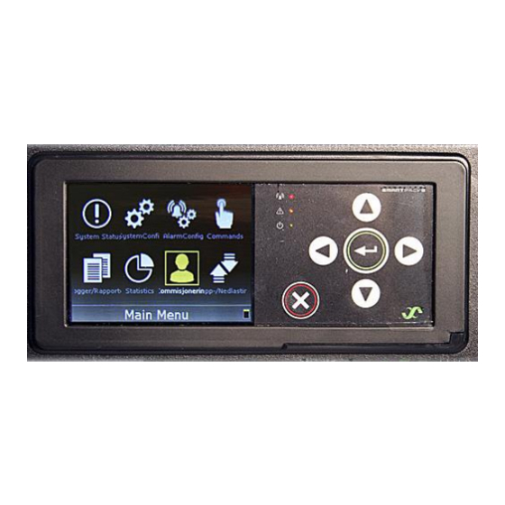
Page 9: Front Panel Operation
2 The Smartpack2 Master Controller Front Panel Operation This chapter describes the Smartpack2 Master controller’s keys and indicators, and how to operate the Smartpack2-based DC power system from the controller’s front panel. Graphical Color ”Alarm” LED lamp (red) Display 3.2” TFT 32k, QGVA “Warning”... -
Page 10: Software Menus
2 The Smartpack2 Master Controller Software Menus The Smartpack2-based system’s functionality is accessed via a network of software menus and submenus, enabling you to configure and control the whole power system from the controller’s front panel. When browsing the menus, the Menu Level Indicator shows the menu level you are in. -
Page 11: Controller Access - Via Stand-Alone Pc
2 The Smartpack2 Master Controller Controller Access — Via Stand-alone PC You can access the Smartpack2 Master controller directly from a stand-alone computer, or via a Local Area Network (LAN) if available. Each controller is shipped with a unique Eltek MAC address stored inside the controller and marked on the controller’s label, and with the fixed IP address <192.168.10.20>. -
Page 12: Technical Specifications
2 The Smartpack2 Master Controller Technical Specifications User's Guide Smartpack2 Master Controller 350020.013, Issue 2.0, 2014 Jan... -
Page 13: Firmware Upgrade Controller
2 The Smartpack2 Master Controller Firmware Upgrade Controller Upgrade of the Smartpack2 Master controller’s firmware, while the system is live, is performed either via the controller’s Ethernet port -- using the “Eltek Network Utility” program (ENU) — or via the controller’s SD card. -
Page 14: Firmware Upgrade From A Computer
2 The Smartpack2 Master Controller Firmware Upgrade from a Computer The Smartpack2 Master controller can be upgraded using a personal computer to run the “Eltek Network Utility” program (ENU), to transfer the firmware file to the controller. Do following: Open the controller using your fingers or a pen, see steps (1), (2) in the figure on page 13 or chapter “Opening and Closing Smartpack2 Master Controller”, on page 7... -
Page 15: About Power System Configuration
3 About Power System Configuration 3. About Power System Configuration The Eltek DC power supply system’s functionality represents a vast set of functions, characteristics or capabilities implemented in the hardware and software of the controllers, control units and nodes connected to the system’s CAN bus. -
Page 16: System Status Options
Rectifier, Load, etc. Refer to these topics (Mains, Rectifiers, etc.) for more information about the available Alarm Monitors parameters. Read also the topic “Typical Parameters for Alarm Monitors” on page 26. User's Guide Smartpack2 Master Controller 350020.013, Issue 2.0, 2014 Jan... -
Page 17: Commands Options
<0003>, which may be changed for security reasons. The commands are organized in following groups: System Commands Battery Commands Outputs Test Read about “Output Test Commands” on page 31 User's Guide Smartpack2 Master Controller 350020.013, Issue 2.0, 2014 Jan... -
Page 18: Logs And Reports Options
1000 chronological events. Each log entry contains event text, event action, time and date. When the log is full, the oldest value is overwritten. The log is stored in EEPROM. Example of alarm log in Smartpack2 Master Controller’s submenu: Logs/Report > Active Alarms Description... -
Page 19: Statistics Options
Example of the Statistics table available in Smartpack S controller’s submenu: Statistics Description Reset Average Peak Note BatteryVoltage 52,48 52,61 BatteryCurrent Battery Temp Load Current Rectifier Current Mains Volt 1 User's Guide Smartpack2 Master Controller 350020.013, Issue 2.0, 2014 Jan... -
Page 20: Commissioning Options
NOTICE: The Smartpack2 Master controller uses an external SD card as data storage device, and the Smartpack S controller uses embedded Flash Memory. In addition to firmware, this group’s options offer you the possibility of uploading and saving system configuration files to the controller’s data storage device. -
Page 21: Sd Card Storage - Overview Firmware Files (Binary Format)
3.01 SD Card Storage - Overview Firmware Files (Binary Format) You can store binary files in the Smartpack2 Master controller’s SD card (data storage device) and use them for firmware upgrading of controllers and control units, as well as for exporting and importing configuration files. -
Page 22: Flash Memory Storage
When upgrading the firmware of controllers and control units — if several units of the same type are connected to the CAN bus — the Smartpack2 Master controller will request you to specify the CAN bus ID number of the unit to upgrade. -
Page 23: Alarm Monitors
When the input signal has reached a certain limit or criteria for a certain period of time, the alarm monitor raises an alarm. This period of time is called Time User's Guide Smartpack2 Master Controller 350020.013, Issue 2.0, 2014 Jan... - Page 24 You can restart the monitor’s peak value measurements. In addition, you can configure the alarm monitors with a description of the alarm monitor and other configuration parameters. User's Guide Smartpack2 Master Controller 350020.013, Issue 2.0, 2014 Jan...
-
Page 25: Types Of Alarm Monitors
(Description). This is useful for alarm monitors of the type “ProgInput X.Y”, but you should be careful changing the name of other system alarm monitors. Read also the “Alarm Monitor dialog boxes” topic in PowerSuite Online Help. User's Guide Smartpack2 Master Controller 350020.013, Issue 2.0, 2014 Jan... -
Page 26: Typical Parameters For Alarm Monitors
Selects among delay time options MajorHigh AlarmLevel Upper limit MajorHigh AlarmGroup Major Alarm Selects the alarm group to activate MinorHigh AlarmLevel Lower limit MinorHigh AlarmGroup Minor Alarm Selects the alarm group to activate User's Guide Smartpack2 Master Controller 350020.013, Issue 2.0, 2014 Jan... - Page 27 Major Low lower limit Selects the alarm group to activate The LVD alarm monitors “observe” that the battery voltage (input signal) is within limits, otherwise they activate the LVD contactors (alarm group). User's Guide Smartpack2 Master Controller 350020.013, Issue 2.0, 2014 Jan...
-
Page 28: Alarm Output Groups
The outputs -- alarm relay outputs and or latching contactors (LVLD and LVBD) – are distributed among the power system’s controllers and control units. User's Guide Smartpack2 Master Controller 350020.013, Issue 2.0, 2014 Jan... - Page 29 The assignment procedure is the same, but you group the phone numbers and assign them to Alarm Output Group. Read also topic “Control Unit Modem Callback Setup tab” in PowerSuite Online Help. User's Guide Smartpack2 Master Controller 350020.013, Issue 2.0, 2014 Jan...
- Page 30 Read more in topic “Alarm Outputs Isolation (Output Blocked)” on page 31 Alarm Groups 9 through 17 are unused, and can be assigned when required User's Guide Smartpack2 Master Controller 350020.013, Issue 2.0, 2014 Jan...
-
Page 31: Output Test Commands
NOT trigger any alarm output groups (output relays activation is blocked), except for AOG 18. Also, this command will always activate Alarm Output Group 18 to facilitate external warning of this function being active. User's Guide Smartpack2 Master Controller 350020.013, Issue 2.0, 2014 Jan...
Need help?
Do you have a question about the Smartpack2 and is the answer not in the manual?
Questions and answers