
Related Manuals for Eltek BC2000


Summary of Contents for Eltek BC2000
- Page 1 Disp play Oper ratio n Ma anual 2000 0 and d JC2 Cont trolle ompac ct, Inte grated d, HJ, a and J Fr ront W Wire DC P Power System Doc. No. 2 2055882, Iss Part No. D O600000235 blished 20-Ju un-14...
- Page 2 Eltek regar rding the reli iability, fitne ess, or compa tibility of the e products an nd procedure es described.
-
Page 3: Table Of Contents
Battery Discharge Test ....................26 Boost Mode ......................... 27 Over Temperature ......................28 Temperature Compensation ................... 29 Thermal Runaway ......................30 6. Basic Troubleshooting ..............31 Display Operation Manual BC2000 and JC2000 Controller ~ Doc. No. 2055882, Issue 5.1, June 2014... - Page 4 Battery Management ....................... 49 Generator ..........................50 Thermal ..........................51 Probes, Network, and Display ..................53 Version and Presets ......................54 Revision Table ..................55 Display Operation Manual BC2000 and JC2000 Controller ~ Doc. No. 2055882, Issue 5.1, June 2014...
-
Page 5: Overview
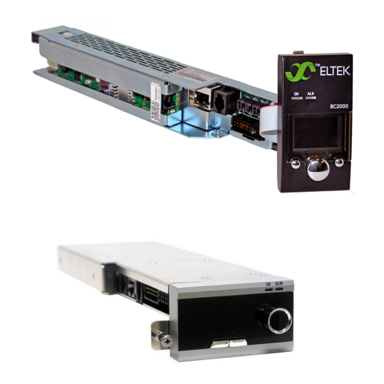
LEDs, and an audible alarm buzzer. This display is the user interface for all system communication devices, such as low voltage disconnect (LVD) and peripheral monitors (PM). Display Operation Manual BC2000 and JC2000 Controller ~ Doc. No. 2055882, Issue 5.1, June 2014... - Page 6 Statu us indicators Disp lay section ontroller ttons and croll knob BC200 00 Controller C2000 Contro oller Figu re 1 – Contro oller Display The disp play screen n is divided in two par rts. The to op part disp plays prima ary plant voltage...
-
Page 7: Status Indicators
4. Temp/Aux – Input ports that accept temperature probes and/or dry-contact relays 5. Alarm Relay – Form-C output alarm relays (requires Eltek cable, sold separately) 6. Display – Connection for the controller display Display Operation Manual BC2000 and JC2000 Controller ~ Doc. No. 2055882, Issue 5.1, June 2014... - Page 8 See Table 2 for the color code for each alarm channel (relay). Select the proper alarm type and connect the cables to the alarming equipment. Display Operation Manual BC2000 and JC2000 Controller ~ Doc. No. 2055882, Issue 5.1, June 2014...
- Page 9 3 on page 31. These relays can be customized through the web interface. For additional details on mapping alarms, refer to the Web Interface Manual BC2000/JC2000 Controller, Doc. No. 2056625. Display Operation Manual BC2000 and JC2000 Controller ~ Doc. No. 2055882, Issue 5.1, June 2014...
-
Page 10: References
BC2000/JC2000 Controller, Doc. No. 2056625. Communication with the LAN port is through an Ethernet cross-over cable or straight-through cable to a router. This cable is not supplied by Eltek. The controller can be connected to a LAN or directly to a PC. Ethernet cables are not supplied by Eltek. -
Page 11: Controller Installation And Setup
Display Ope ration Manual B BC2000 and JC20 000 Controller ~ ~ Doc. No. 20558 882, Issue 5.1, J une 2014... -
Page 12: Controller Input Ports
“TEMP/A AUX” in the e figures be elow. TEMP/A AUX Ports gure 5 – TEM P/AUX Ports s (BC2000) TEMP P/AUX Ports gure 6 – TEM MP/AUX Ports s (JC2000) Tempe erature Probe In nput Up to fo... - Page 13 TEMP/A UX port on n the contr oller. 4. R epeat for m multiple ba attery strin ngs. Display Ope ration Manual B BC2000 and JC20 000 Controller ~ ~ Doc. No. 20558 882, Issue 5.1, J une 2014...
-
Page 14: Controller Settings
If the number is different from the default profile (01), then contact Eltek technical support at 1-800-435-4872 for a copy of the settings specified by that profile number. Display Operation Manual BC2000 and JC2000 Controller ~ Doc. No. 2055882, Issue 5.1, June 2014... -
Page 15: Viewing Information (Login Not Required)
The first page to appear on the home screen indicates system status and internal temperature. If any alarms are triggered, the flashing Alarm tab appears above the left button. Display Operation Manual BC2000 and JC2000 Controller ~ Doc. No. 2055882, Issue 5.1, June 2014... - Page 16 Presets are subsets of profiles. Up to three presets can be configured for parameter values only (not alarm mapping). These three presets are typically called “A”, “B”, and “C”. Preset A is the default preset. Display Operation Manual BC2000 and JC2000 Controller ~ Doc. No. 2055882, Issue 5.1, June 2014...
-
Page 17: Screen Saver
The timeout period that triggers the screen saver is configurable. Once the timeout period expires, the system automatically logs out and goes into screen saver mode. The screen saver shows system voltage and current. Display Operation Manual BC2000 and JC2000 Controller ~ Doc. No. 2055882, Issue 5.1, June 2014... -
Page 18: Main Menu
• Login (only appears when no user is logged in) • System • Alarming • Modules • Activate • Battery Mgt • Generator • Thermal • Probes • Network • Display • Version Display Operation Manual BC2000 and JC2000 Controller ~ Doc. No. 2055882, Issue 5.1, June 2014... -
Page 19: View Shunt Current
Main Menu ► Version ► Controller ► Display View IP Address The controller’s IP address can be found as follows: Main Menu ► Network ► IP Address Display Operation Manual BC2000 and JC2000 Controller ~ Doc. No. 2055882, Issue 5.1, June 2014... -
Page 20: Settings And Configuration (Login Required)
LAN interface. See the document 2056625 – BC2000/JC2000 LAN Interface Manual for details. Refer to the “Appendix – Controller Menu Trees,” which begins on page 41, for comprehensive menu trees. Display Operation Manual BC2000 and JC2000 Controller ~ Doc. No. 2055882, Issue 5.1, June 2014... -
Page 21: Change System Time And System Date
• Aux NO – set the port to monitor a normally open form-C relay. • Aux NC – set the port to monitor a normally closed form-C relay. Display Operation Manual BC2000 and JC2000 Controller ~ Doc. No. 2055882, Issue 5.1, June 2014... -
Page 22: Change Float Voltage
(far right connector). This input port (“Probe 4”) should be set to “Auxiliary – Normally Open.” NOTE: To setup the input ports, refer to the section “Input Port Setup” on page 21. Display Operation Manual BC2000 and JC2000 Controller ~ Doc. No. 2055882, Issue 5.1, June 2014... -
Page 23: Restore Preset
(requires an administrator login). Presets are non-adjustable, but custom presets can be requested through Eltek. Main Menu ► Preset ► Current ► Edit Display Operation Manual BC2000 and JC2000 Controller ~ Doc. No. 2055882, Issue 5.1, June 2014... -
Page 24: Change Temperature Units
Change Beep Volume The beep volume can be adjusted on a scale of 0% to 100% as follows: Main Menu ► Display ► Beep Volume ► Edit Display Operation Manual BC2000 and JC2000 Controller ~ Doc. No. 2055882, Issue 5.1, June 2014... -
Page 25: Change Screen Saver Settings
• Version—ring generator software version • Model—module model number • Serial—module serial number The ring generator menu is accessed as follows: Main Menu ► Modules ► Ringers (if installed) Display Operation Manual BC2000 and JC2000 Controller ~ Doc. No. 2055882, Issue 5.1, June 2014... -
Page 26: Battery Features (Login Required)
5. B Battery y Feat ures (L Login R Require The con ntroller con tains featu ures for the e protectio on, testing, , and monit toring of batterie es. These f features in clude batt ery dischar rge test, b oost or eq ualize, batt tery... -
Page 27: Boost Mode
• A An alarm ot her than h igh voltage e is triggere Display Ope ration Manual B BC2000 and JC20 000 Controller ~ ~ Doc. No. 20558 882, Issue 5.1, J une 2014... -
Page 28: Over Temperature
• External Maximum – when the external temperature reading exceeds this value an over temperature alarm is issued. Display Operation Manual BC2000 and JC2000 Controller ~ Doc. No. 2055882, Issue 5.1, June 2014... -
Page 29: Temperature Compensation
• Boost Adjust – if enabled, allows the Boost feature to activate during an active temperature compensation state. Display Operation Manual BC2000 and JC2000 Controller ~ Doc. No. 2055882, Issue 5.1, June 2014... -
Page 30: Thermal Runaway
Runaway Voltage. • Runaway V – the voltage value that the rectifier output falls to when the Runaway Temperature value is exceeded. Display Operation Manual BC2000 and JC2000 Controller ~ Doc. No. 2055882, Issue 5.1, June 2014... -
Page 31: Basic Troubleshooting
Distribution Alarm Auxiliary Alarm System Redundant Capacity Alarm Rectifier Current Share Alarm Single Rectifier Fail Alarm Multiple Rectifier Fail Alarm Module Communication Alarm System Over Display Operation Manual BC2000 and JC2000 Controller ~ Doc. No. 2055882, Issue 5.1, June 2014... - Page 32 Distrib./PM Comm. Fail Alarm Rectifier Current Limit Multiple Rectifier Limit Unmapped Address Alarm Configuration Error Alarm Display Needs Firmware Alarm Unused Alarm DGU Failed to Start Alarm Display Operation Manual BC2000 and JC2000 Controller ~ Doc. No. 2055882, Issue 5.1, June 2014...
- Page 33 I Share Alarm – faulty rectifier(s). Load Share NOTE: AC OK, and DC OK LEDs of the Faulty Rectifier(s) (not sharing the load), Alarm may still be GREEN Display Operation Manual BC2000 and JC2000 Controller ~ Doc. No. 2055882, Issue 5.1, June 2014...
- Page 34 Responding If the message “Controller not responding” returns, or if the message “Starting App” persists (without returning to the main screen), contact Eltek Technical Support. Display Operation Manual BC2000 and JC2000 Controller ~ Doc. No. 2055882, Issue 5.1, June 2014...
-
Page 35: Appendix - Parameter Settings And Ranges
Eltek Technical S Support at t 1-866-435 4872 fo r the custo om profile s settings. Display Ope ration Manual B BC2000 and JC20 000 Controller ~ Doc. No. 2055 5882, Issue 5.1, June 2014... - Page 36 Enables an alarm to indicate if any rectifier Disabled / Comm Fail either stops communicating, or is removed Disabled Enabled from the shelf Display Operation Manual BC2000 and JC2000 Controller ~ Doc. No. 2055882, Issue 5.1, June 2014...
- Page 37 Probe (1–8) Disabled If an Eltek temp probe is installed, the probe Aux N.C. port is automatically set to “T Probe” Dist N.O. Dist N.C. Display Operation Manual BC2000 and JC2000 Controller ~ Doc. No. 2055882, Issue 5.1, June 2014...
- Page 38 Enables or disables the generator feature Disabled Enabled Select the type of generator in use (either air- Air Cooled / Type Other cooled or “other”) Other Display Operation Manual BC2000 and JC2000 Controller ~ Doc. No. 2055882, Issue 5.1, June 2014...
- Page 39 Runaway Clamp Voltage (Runaway V) The voltage to which the controller reduces Runaway V while temperature is above the Runaway 50 V 45 – 50 V Temperature value Display Operation Manual BC2000 and JC2000 Controller ~ Doc. No. 2055882, Issue 5.1, June 2014...
- Page 40 Administrator Login 5001 0000 – 9999 (modify parameters) *Requires controller TEMP/AUX connections be made for proper operation. Consult relevant sections within this document for details. Display Operation Manual BC2000 and JC2000 Controller ~ Doc. No. 2055882, Issue 5.1, June 2014...
-
Page 41: Appendix - Controller Menu Trees
NOTE: This document revision (Issue 5.1) is based on controller firmware version 4.02.10 and display firmware version 7.02.10. Subsequent versions may include minor changes to available features and/or menus. Display Operation Manual BC2000 and JC2000 Controller ~ Doc. No. 2055882, Issue 5.1, June 2014... - Page 42 SCREEN SAVER SERIAL CONFIGURABLE BUILD DATE VERSION PARAMETER DISPLAY CONTROLLER CONTROLLER FIXED INFORMATION DISPLAY VERSION DISPLAY MODEL EXECUTABLE PRESETS SERIAL CURRENT BUILD DATE BUILD TIME Display Operation Manual BC2000 and JC2000 Controller ~ Doc. No. 2055882, Issue 5.1, June 2014...
- Page 43 DISPLAY DISPLAY VERSION VERSION PRESETS PRESETS LOGOUT** *LOGIN only appears when there is no current login session at the display. **LOGOUT only appears after login. Display Operation Manual BC2000 and JC2000 Controller ~ Doc. No. 2055882, Issue 5.1, June 2014...
-
Page 44: System
• Date: Depends on date format (below) • Time: HH:MM:SS (am/pm, if “12 Hour” time format ) • Date Format: MM/DD/YYYY or DD/MM/YYYY • Time Format: 24 Hour/12 Hour Display Operation Manual BC2000 and JC2000 Controller ~ Doc. No. 2055882, Issue 5.1, June 2014... -
Page 45: Alarming
• Low Voltage: ##.## V • Comm Fail: Disabled/Enabled • I Share: Disabled/Enabled • Redundancy: Disabled/Enabled • Audible (Audible Alarm): Disabled, Major Alarms, Minor Alarms, Major+Minor, Any Alarm Display Operation Manual BC2000 and JC2000 Controller ~ Doc. No. 2055882, Issue 5.1, June 2014... -
Page 46: Modules
Modules Display Operation Manual BC2000 and JC2000 Controller ~ Doc. No. 2055882, Issue 5.1, June 2014... - Page 47 Probe (1-8) – Input type; Disable; AUX_NO, AUX_NC Relay polarity – Normal Energy / Normal De-energy Relay type – On-Off / pulse Pulse width – sec_(2_86400) Display Operation Manual BC2000 and JC2000 Controller ~ Doc. No. 2055882, Issue 5.1, June 2014...
-
Page 48: Activate
Mode” on page 27. • Lamptest: Illuminates all LEDs (controller and rectifiers) Configurable parameters: • Relays – Controller output relays Test Mode: Disabled/Enabled Relay (A – F): Inactive/Active Display Operation Manual BC2000 and JC2000 Controller ~ Doc. No. 2055882, Issue 5.1, June 2014... -
Page 49: Battery Management
Alarm Delay: (0 – 30) mins. Auto Mode: Disabled/Enabled • Boost (Battery Boost) State: Disabled/Enabled Duration: HH:MM:SS (Maximum: 17:59:59) Voltage: ##.## V Stop Current: (0 – 255) A Display Operation Manual BC2000 and JC2000 Controller ~ Doc. No. 2055882, Issue 5.1, June 2014... -
Page 50: Generator
• Generator State: Disabled/Enabled Type: Air Cooled / Other Battery AH (Battery Amp-Hours): (20 – 1000) AH Discharge LVL (Discharge Level): (35 – 85) % Display Operation Manual BC2000 and JC2000 Controller ~ Doc. No. 2055882, Issue 5.1, June 2014... -
Page 51: Thermal
• T Comp (Temperature Compensation) Status: Disabled/Enabled Sense: Internal/External Boost Adjust: Disabled/Enabled High T Start (High Temperature Start): (25 – 60)°C / (77 – 140)°F Display Operation Manual BC2000 and JC2000 Controller ~ Doc. No. 2055882, Issue 5.1, June 2014... - Page 52 Low Slope: (0 – 250) mV/°C Low V Stop (Low Voltage Stop): ##.## V • T Runaway (Thermal Runaway) Runaway Temp: (45 – 70)°C Runaway V (Runaway Voltage): ##.## V Display Operation Manual BC2000 and JC2000 Controller ~ Doc. No. 2055882, Issue 5.1, June 2014...
-
Page 53: Probes, Network, And Display
Brightness: (0 – 100) % Beep Volume: (0 – 100) % Timeout: (1 – 60) mins. Screen Saver: Glow, Bouncing Box, Volts & Amps, Heartbeat Display Operation Manual BC2000 and JC2000 Controller ~ Doc. No. 2055882, Issue 5.1, June 2014... -
Page 54: Version And Presets
BUILD DATE DISPLAY DISPLAY BUILD TIME VERSION VERSION PRESETS CURRENT PRESETS LOGOUT LOGOUT Configurable parameters: • Presets Current: Preset A, Preset B, or Preset C Display Operation Manual BC2000 and JC2000 Controller ~ Doc. No. 2055882, Issue 5.1, June 2014... -
Page 55: Revision Table
1-800-43 35-4872. Docume ents and ot ther Eltek p product inf formation a are availab ble online at eltek.sh harefile.com Display Ope ration Manual B BC2000 and JC20 000 Controller ~ Doc. No. 2055 5882, Issue 5.1, June 2014... - Page 56 Doc. No. 2 2055882, Iss ue 5.1 ublished 20-J Jun-14 ww.eltek.com US Office: Intern ational: Eltek, Inc. ltek AS 2925 E Plano o Pkwy, Plano, TX 75074, USA Gråterudv. 8, P Pb 2340 Strømsø, , 3003 Drammen, N Norway Phone: +1 (4...
Need help?
Do you have a question about the BC2000 and is the answer not in the manual?
Questions and answers