
Related Manuals for Eltek Smartpack S


Summary of Contents for Eltek Smartpack S
- Page 1 User Guide Smartpack S Controller Monitoring and Control Units Flatpack S DC Power Supply Systems 350030.013...
- Page 2 Always tighten screws and bolts with the torque values recommended in the documentation. For safety reasons, the commissioning and confi guration of the equipment is only to be performed by Eltek’s personnel or by author-...
- Page 3 — for any purpose without the explicit written permission of Eltek. Copyright ©: Eltek, 2012 Eltek’s Part Number: 242100.410 Smartpack S Controller Doc No: 350030.013 Issue 1.0, 2012 Jun Published 2012-07-05 mafeno User Guide • Smartpack S Controller...
-
Page 4: Table Of Contents
Table of Contents 1. Introduction ..................5 About this Guide....................... 5 System Diagram — Flatpack S Power System ............5 2. The Smartpack S Controller ............6 Key Features ........................6 Installing Smartpack S Controllers ................7 Removing Smartpack S Controllers ..................7 Mounting Smartpack S Controllers ..................7... -
Page 5: Introduction
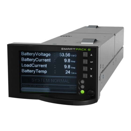
Introduction 1. Introduction The advanced Smartpack S controllers are developed for Eltek’s Flatpack S sys- tem platform, suitable for small and medium telecom and industrial DC power sys- tems. About this Guide This booklet provides users of Smartpack S-based DC power systems with the re- quired information for operating the system using the Smartpack S’s front panel. -
Page 6: The Smartpack S Controller
◊ Uploading and downloading of firmware and configuration files via PC ◊ Buzzer for audio indication of alarm conditions and key pressure feedback Read also chapter “Technical Specifications” on page 16, for more details. User Guide • Smartpack S Controller... -
Page 7: Installing Smartpack S Controllers
Blind panel’s handle position • To remove a blind panel Removing: Push down and push the panel’s handle downwards and pull out to release Insert pull out to release the panel User Guide • Smartpack S Controller... -
Page 8: Accessing The Controller's Ethernet Port
The Ethernet port can also be accessed from the power system’s rear, for more permanent connections of the system to a LAN. A dedicated Ethernet cable may be ordered from Eltek, when the rear cable entry to the controller becomes too tight. -
Page 9: Location Of Connector, Communication Ports
Ground Figure 2. Location of pluggable terminal blocks, RS232/RS485 port and Ethernet connector in the Smartpack S controller (the pluggable terminals may be black or green) All the controller’s system connections to the system’s backplane are implement- ed via an edge connector, when inserting the controller in the power system. -
Page 10: Connection Drawing
(Via edge connector to the system’s backplane) Figure 3. Connection Drawing for Smartpack S controller The configurable inputs 1 through 4 operate in the range of max. – 10 to +10VDC, and are intended for great accurate measurements, e.g. for temperature sensing using an external temperature NTC probe. -
Page 11: Can Bus Termination
Figure 4. Example of CAN bus addressing and termination in a Flatpack S power sys- tem with Smartpack S-based control system and some CAN nodes connected the CAN bus When connecting more CAN nodes to the bus, you have to remove the CAN bus termination plug from one of the CAN bus ends, and plug it in one of the CAN ports on the last connected CAN node. -
Page 12: Configuration
The controller’s ID # corresponds to the DIP switch’s binary value plus 1 ** The DIP switch positions above applies to all controllers, except for Smartpack2 Master and Compack controllers, which have unchangeable ID# 11 and 1 respectively Table 1. Smartpack S controller’s DIP switch addressing User Guide • Smartpack S Controller... -
Page 13: Front Panel Operation
ON red Alarm (Major alarm, Critical Alarm) Table 2. Description of the Smartpack S controller’s LED illumination status Front Keys You can operate the power system navigating intuitively through the graphical menu structure via the following 4 front keys. We recommend using a pen or similar tool to press the keys, as they are small. -
Page 14: Software Menus
(Level 3) Example Submenu “Monitors Statistics” (Level 3) From a PC’s web browser, via WebPower, or running the PowerSuite program, you can also access the complete system functionality, described in the programs’ On- line Help. User Guide • Smartpack S Controller... -
Page 15: Controller Access - Via Stand-Alone Pc
You can access the Smartpack S controller directly from a stand-alone computer, or via a Local Area Network (LAN) if available. Each controller is shipped with a unique Eltek MAC address stored inside the con- troller and marked on the controller’s label, and with the fixed IP address <192.168.10.20>. -
Page 16: Technical Specifications
ETSI EN 300 019: 2-1 (Class 1.2), 2-2 (Class 2.3) & 2-3 (Class 3.2) ROHS compliant *) As part of CA0603.000 Flatpack S 3U Marine system Specifications are subject to change without notice Doc 242100.410.DS3 – v1 User Guide • Smartpack S Controller... -
Page 17: Firmware Upgrade Controller
Firmware Upgrade Controller Upgrade of the Smartpack S controller’s firmware, while the system is live, is per- formed via the controller’s Ethernet port, using the “Eltek Network Utility” program (EVIPSetup.exe) to transfer the firmware file to the controller. Upgrading the firmware does not delete or change any of the configuration and calibration values stored in the controllers. -
Page 18: Overview Lan Devices And Firmware Files (Pc - S19 Format)
The Smartpack S Controller Overview LAN Devices and Firmware Files (PC - S19 Format) The “Eltek Network Utility” program <EVIPSetup.exe> will transfer the specific firmware file (s19-format) from a LAN connected computer to the device (or hard- ware platform). LAN Device... -
Page 19: About Power System Configuration
About Power System Configuration 3. About Power System Configuration The Eltek DC power supply system’s functionality represents a vast set of func- tions, characteristics or capabilities implemented in the hardware and software of the controllers, control units and nodes connected to the system’s CAN bus. -
Page 20: System Status Options
The default Service Access Level password or Pin-Code is <0003>. We strongly recommend changing the passwords as soon as the power system is installed. The available Alarm Monitors are organized in system-oriented groups: Mains, Gen- erator, Rectifier, Load, etc. User Guide • Smartpack S Controller... -
Page 21: Commands Options
The commands are organized in following groups: • System Commands • Battery Commands • Outputs Test Read about "Output Test Commands" on page User Guide • Smartpack S Controller... -
Page 22: Logs And Reports Options
Battery Test Log The Battery Test Log is displayed in a results table; each row of data represents a battery test. Also, the battery quality, calculated by completed battery tests, and other test parameters are displayed. User Guide • Smartpack S Controller... -
Page 23: Statistics Options
This logical group presents a generic description of the steps required to carry out commissioning tasks of the power system. Refer also to the system’s user documentation, and to the Commissioning Proce- dure pull-out list in the system’s quick start guide. User Guide • Smartpack S Controller... -
Page 24: Up/Download Options (Data Storage Device)
Also, you can upload a similar, specific System Configuration file <UNIT_nn.HEX> to the controller or to any connected CAN unit, e.g. for automatic configuration of specific functions The “nn” in the file name specifies the unit’s CAN bus address. User Guide • Smartpack S Controller... -
Page 25: Sd Card Storage - Overview Firmware Files (Binary Format)
Any node UNIT_aa.HEX Configuration File (Save/Load) All types The “aa” refers to the CAN bus address or ID number. E.g. “UNIT_82.HEX” could be the configuration file for I/O Monitor with CAN bus address 82. User Guide • Smartpack S Controller... -
Page 26: Flash Memory Storage
It is not recommended to use the FTP client embedded in Windows Explorer. WARNING: Before uploading files to the Flash memory (4MB), check that there is enough storage space. Also, consider deleting files that are no longer necessary. User Guide • Smartpack S Controller... -
Page 27: Alarm Monitors
You have to Enable the alarm monitor so that it functions • Type of alarm reset You can select whether the alarm generated by monitor can be reset manually, or automatically (when the event that caused the alarm is no longer true) User Guide • Smartpack S Controller... - Page 28 The alarm monitor stores all input signal measurements and performs average calculations every minute. Then, the monitor continuously displays the input signal average value, and the period of time the input signal has been measured. You can restart the monitor’s average calcu- lations. User Guide • Smartpack S Controller...
-
Page 29: Types Of Alarm Monitors
The power system’s controller uses following types of alarm monitors, determined by the monitor’s type of input signal: • Logical Alarm Monitors (L1) • Numeric Alarm Monitors (N1, N2%) • Analogue Alarm Monitors (A2, A4) • Special Alarm Monitors (LVD) User Guide • Smartpack S Controller... - Page 30 Selects among delay time options (b) MajorHigh AlarmLevel Upper limit MajorHigh AlarmGroup Major Alarm Selects the alarm group to activate MinorHigh AlarmLevel Lower limit MinorHigh AlarmGroup Minor Alarm Selects the alarm group to activate User Guide • Smartpack S Controller...
- Page 31 Selects the alarm group to activate Major Low lower limit Selects the alarm group to activate The LVD alarm monitors “observe” that the battery voltage (input signal) is within limits, otherwise they activate the LVD contactors (alarm group). User Guide • Smartpack S Controller...
- Page 32 Delay Time after Disconnect Enter the Time delay or number of seconds the LVD contactor has to be tripped or disconnected, before the alarm monitor is allowed to reconnect the LVD contactor User Guide • Smartpack S Controller...
-
Page 33: Alarm Output Groups
The outputs of Smartnode control units are telephone numbers, instead of relay outputs. The assignment procedure is the same, but you group the phone numbers and assign them to Alarm Output Group. Read also topic “Control Unit Modem Callback Setup tab” in PowerSuite Help. User Guide • Smartpack S Controller... - Page 34 “OutpBlocked, AOG” group, e.g. to activate a lamp or alarm bell when the alarm output relays are blocked. Read more in topic "Alarm Outputs Isolation (Output Blocked)" on page • Alarm Groups 9 through 17 are unused, and can be assigned when re- quired User Guide • Smartpack S Controller...
-
Page 35: Output Test Commands
NOT trigger any alarm output groups (output relays activation is blocked), except for AOG 18. Also, this command will always activate Alarm Output Group 18 to facilitate external warning of this function being active. User Guide • Smartpack S Controller... - Page 36 Headquarters: Eltek Visitor address: Gråterudveien 8, 3036 Drammen, Norway Phone: +47 32 20 32 00 Fax: +47 32 20 32 10...
Need help?
Do you have a question about the Smartpack S and is the answer not in the manual?
Questions and answers
Hi, how to perform a restore of factory default on Smartpack S controller?