Advertisement
Quick Links
RCD550 interface installation manual_v120303
[product type: FV‐RCD550]
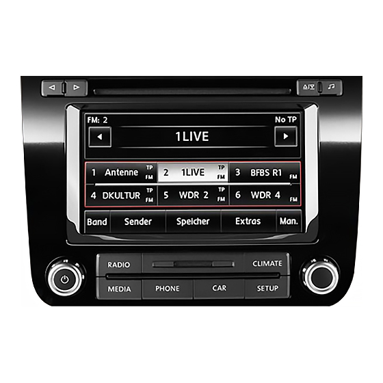
This interface can insert High definition RGB navigation video,
AV and reverse camera video onto RCD550 car screens. The features
are:
A daughter board is used to insert High definition RGB
navigation and other video onto
the OEM screen.
Oem NAVI key is used to switch
the
video
input.
camera
trigger
automatically generated.
Guaranteed digital video quality
on screen. Which also offer very
nice reliability.
1.System connection
The daughter board with isolation tube is used to switch
the video from board to LCD.
Insert the red ribbon of LCD onto the daughter board,
while insert the white ribbon back to OEM PCB socket.
The 4P touch panel should go
through the daughter board
thus the touch can be used to
installed
navigation
computer.
Touch
external navi
The CAN box's 4 input wires should be wired to the rear of the RCD550:
Red with fuse‐‐‐‐to‐‐‐constant BATT or ACC
Brown ‐‐‐‐to‐‐‐ car chassis for Ground.
Blue ‐‐‐‐to‐‐‐ CAN bus+ [printed on the top of head unit.]
1 / 4
Gray ‐‐‐‐to‐‐‐ CAN bus‐
Correct connection will make the can box's LED when working.
Reverse
signal
is
3 keys for
color tuning.
Extra keypad
to
To Interface's
CTRL port
NAVI AV1,AV2 Rearview
Advertisement

Related Manuals for Volkswagen RCD550


Summary of Contents for Volkswagen RCD550
- Page 1 RCD550 interface installation manual_v120303 [product type: FV‐RCD550] This interface can insert High definition RGB navigation video, AV and reverse camera video onto RCD550 car screens. The features are: A daughter board is used to insert High definition RGB navigation and other video onto the OEM screen. Oem NAVI key is used to switch the video input. Reverse camera trigger signal is ...
- Page 2 6 IR programme when once to ON OFF for normal work. Touch calibration when get to ON >5 times. 7,8 DIP8=DOWN: for RCD550 (important) DIP8=OFF(UP side) means factory test mode of this interface, the screen may show noise or black screen[not damage anything], if the installer can not see the inserted video, probably this dip goes wrong. 2.Interface Settings ...
- Page 3 in this case, the white wire of the 6P wire between CAN box and interface should be cut off.[suggested.] 3. CTRL port There is a 8‐pin extra CTRL port on the interface, the RCD550 is already using it to switch the touch panel 4P signals. The installer does not need to use the other functions of this 4P in normal situation. For experienced users, this port may be used to get extra functions. Ctrl port signal definitions: Pin 1,2 +5V output voltage for sound‐switch‐relay, when AV1 is selected=5V, 0V when AV2 selected. Max 3A. ...
- Page 4 Parameters No. name parameter 1 RGB video amplitude 0.7Vpp with 75 ohm impedance NTSC resolution [400X240,480X240] of navigation is allowed. Suggested: 800X480 RGB HD. 2 sync amplitude in RGB‐navi port 3~5Vpp with 5K ohm impedance Sync should be NTSC composite with negative polarity. 3 Av1,Av2, cam video amplitude 0.7Vpp with 75 ohm impedance 4 Av1,Av2, cam standard NTSC/PAL/SECAM automatic switch 5 6 Normal work Power consumption 2.4W [0.2A @12V] 7 Standby current < 5mA 8 Standby start 10 seconds after the users switch off the CD unit. 9 Reverse trigger threshold >5V trigger 10 Work temperature ‐40 ~ +85C ...
Need help?
Do you have a question about the RCD550 and is the answer not in the manual?
Questions and answers