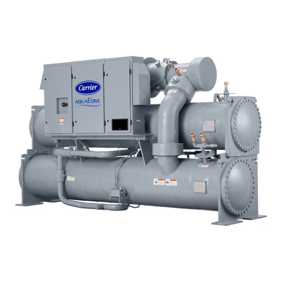
Carrier AquaEdge 23XRV Start-Up, Operation And Maintenance Instructions Manual
High-efficiency variable speed screw chiller with
greenspeed intelligence and pic iii controls 50/60 hz hfc-134a
Hide thumbs
Also See for AquaEdge 23XRV:
- Installation instructions manual (68 pages) ,
- Start-up, operation and maintenance instructions manual (92 pages) ,
- Controls operation and troubleshooting (80 pages)
Table of Contents
Advertisement
Quick Links
Start-Up, Operation and Maintenance
SAFETY CONSIDERATIONS
Screw liquid chillers are designed to provide safe and
reliable service when operated within design specifica-
tions. When operating this equipment, use good judg-
ment and safety precautions to avoid damage to
equipment and property or injury to personnel.
Be sure you understand and follow the procedures and
safety precautions contained in the machine instruc-
tions, as well as those listed in this guide.
DANGER
Failure to follow these procedures will result in severe per-
sonal injury or death.
DO NOT VENT refrigerant relief devices within a build-
ing. Outlet from rupture disc or relief valve must be vented
outdoors in accordance with the latest edition of ANSI/
ASHRAE 15 (American National Standards Institute/
American Society of Heating, Refrigerating, and Air-Con-
ditioning Engineers). The accumulation of refrigerant in an
enclosed space can displace oxygen and cause
asphyxiation.
PROVIDE adequate ventilation in accordance with ANSI/
ASHRAE 15, especially for enclosed and low overhead
spaces. Inhalation of high concentrations of vapor is harm-
ful and may cause heart irregularities, unconsciousness, or
death. Intentional misuse can be fatal. Vapor is heavier than
air and reduces the amount of oxygen available for breath-
ing. Product causes eye and skin irritation. Decomposition
products are hazardous.
DO NOT USE OXYGEN to purge lines or to pressurize a
machine for any purpose. Oxygen gas reacts violently with
oil, grease, and other common substances.
DO NOT USE air for leak testing. Use only refrigerant or
dry nitrogen.
NEVER EXCEED specified test pressures, VERIFY the
allowable test pressure by checking the instruction litera-
ture and the design pressures on the equipment nameplate.
DO NOT VALVE OFF any safety device.
BE SURE that all pressure relief devices are properly
installed and functioning before operating any machine.
RISK OF INJURY OR DEATH by electrocution. High (or
medium) voltage is present on motor leads even though the
motor is not running. Open the power supply disconnect
before touching motor leads or terminals.
Manufacturer reserves the right to discontinue, or change at any time, specifications or designs without notice and without incurring obligations.
Catalog No. 04-53230011-01
High-Efficiency Variable Speed Screw Chiller with
Instructions
Printed in U.S.A.
Form 23XRV-5SS
®
Greenspeed
Intelligence and PIC III Controls
Failure to follow these procedures may result in personal
injury or death.
DO NOT USE TORCH to remove any component. System
contains oil and refrigerant under pressure.
To remove a component, wear protective gloves and gog-
gles and proceed as follows:
a. Shut off electrical power to unit.
b. Recover refrigerant to relieve all pressure from sys-
tem using both high-pressure and low pressure ports.
c. Traces of vapor should be displaced with nitrogen
and the work area should be well ventilated. Refrig-
erant in contact with an open flame produces toxic
gases.
d. Cut component connection tubing with tubing cutter
and remove component from unit. Use a pan to catch
any oil that may come out of the lines and as a gage
for how much oil to add to the system.
e. Carefully unsweat remaining tubing stubs when nec-
essary. Oil can ignite when exposed to torch flame.
DO NOT USE eyebolts or eyebolt holes to rig heat
exchangers or the entire assembly.
DO NOT work on high (or medium) voltage equipment
unless you are a qualified electrician.
DO NOT WORK ON electrical components, including
control panels, switches, starters, or oil heater until you are
sure ALL POWER IS OFF and no residual voltage can
leak from capacitors or solid-state components.
LOCK OPEN AND TAG electrical circuits during servic-
ing. IF WORK IS INTERRUPTED, confirm that all cir-
cuits are deenergized before resuming work.
AVOID SPILLING liquid refrigerant on skin or getting it
into the eyes. USE SAFETY GOGGLES. Wash any spills
from the skin with soap and water. If liquid refrigerant
enters the eyes, IMMEDIATELY FLUSH EYES with
water and consult a physician.
NEVER APPLY an open flame or live steam to a refriger-
ant cylinder. Dangerous over pressure can result. When it is
necessary to heat refrigerant, use only warm (110 F [43 C])
water.
DO NOT REUSE disposable (nonreturnable) cylinders or
attempt to refill them. It is DANGEROUS AND ILLE-
GAL. When cylinder is emptied, evacuate remaining gas
pressure, loosen the collar, and unscrew and discard the
valve stem. DO NOT INCINERATE.
CHECK THE REFRIGERANT TYPE before adding
refrigerant to the machine. The introduction of the wrong
refrigerant can cause machine damage or malfunction.
(Warnings continued on next page.)
Pg 1
1016
AquaEdge
23XRV
50/60 Hz
HFC-134a
WARNING
11-14
Replaces: 23XRV-4SS
®
Advertisement
Table of Contents
Troubleshooting

Related Manuals for Carrier AquaEdge 23XRV


Summary of Contents for Carrier AquaEdge 23XRV
-
Page 1: Safety Considerations
® AquaEdge 23XRV High-Efficiency Variable Speed Screw Chiller with ® Greenspeed Intelligence and PIC III Controls 50/60 Hz HFC-134a Start-Up, Operation and Maintenance Instructions SAFETY CONSIDERATIONS WARNING Screw liquid chillers are designed to provide safe and Failure to follow these procedures may result in personal reliable service when operated within design specifica- injury or death. -
Page 2: Table Of Contents
ANSI/ASHRAE 15 than the actual time required to service the equipment. Seal (latest edition). Contact Carrier for further information on circuits being serviced and charge with dry nitrogen to pre- use of this machine with other refrigerants. - Page 3 COMPRESSOR ON......48 Interface ... . . 75 ® Carrier Comfort Network Oil Sump Temperature Control Power Up the Controls and Check the COMPRESSOR OFF.
- Page 4 Oil Strainers ........91 CONTENTS (cont) Page Page...
-
Page 5: Introduction
ABBREVIATIONS AND EXPLANATIONS Frequently used abbreviations in this manual include: CAUTION — Chiller Control Module — Carrier Comfort Network ® This unit uses a microprocessor control system. Do not — Counterclockwise short or jumper between terminations on circuit boards or —... - Page 6 23XRV 40 S – Special 23XRV – High Efficiency Compressor Option Variable Speed Screw Chiller 0 – Full Load Optimized 1 – Part Load Optimized Cooler Size* A1-A6 Voltage Code B1-B6 3 – 380-3-60 30-32 4 – 416-3-60 35-37 5 – 460-3-60 40-42 7 –...
- Page 7 1 — Discharge Pipe 2 — Variable Frequency Drive 3 — Cooler Relief Valve 4 — Compressor Discharge Pipe 5 — International Chiller Visual Controller (ICVC) 6 — Refrigerant Charging Valve 7 — ASME Nameplate, Evaporator 8 — Condenser Relief Valves 9 —...
- Page 8 1 — Motor Terminal Cover Plate 2 — Variable Frequency Drive 3 — International Chiller Visual Controller (ICVC) 4 — Discharge Pipe Relief Valve 5 — Condenser 6 — Oil Reclaim Actuator 7 — Vaporizer Sight Glass 8 — Oil Filter Assembly (Hidden) 9 —...
- Page 9 1 — Motor Terminal Cover Plate 2 — Variable Frequency Drive 3 — International Chiller Visual Controller (ICVC) 4 — Discharge Pipe Relief Valve 5 — Condenser 6 — Oil Reclaim Actuator 7 — Vaporizer Sight Glass 8 — Oil Filter Assembly (Hidden) 9 —...
- Page 10 1 — Compressor Motor Winding Temperature (Hidden) 2 — Vaporizer Temperature 3 — Evaporator Liquid Temperature 4 — Oil Sump Temperature 5 — Oil Sump Pressure 6 — Supply Oil Pressure 7 — Condenser Liquid Temperature (Hidden) a23-1695 8 — Condenser Liquid Flow (Optional) 9 —...
- Page 11 1 — Condenser Pressure 2 — Evaporator Pressure 3 — Compressor Discharge Temperature 4 — Compressor Discharge Pressure 5 — Compressor Discharge High Pressure Switch 6 — Compressor Motor Winding Temperature (Hidden) 7 — Evaporator Refrigerant Liquid Temperature (Hidden) 8 — Condenser Liquid Temperature 9 —...
-
Page 12: Cooler
• sequences chiller start, stop, and recycle under microproces- refrigerant can remove heat from the liquid flowing through its sor control internal tubes. • provides access to other Carrier Comfort Network devices ® This vessel is located underneath the Condenser —... -
Page 13: Refrigeration Cycle
STANDARD 65 KAIC CIRCUIT BREAKER OPTIONAL 100 KAIC CIRCUIT BREAKER (HANDLE SHIPPED LOOSE INSIDE OF CONTROL CENTER FOR FIELD INSTALLATION) a23-1620 Fig. 9 — Standard and 100-KAIC Circuit Breaker Control Center (R Compressor Shown) which forms a liquid seal to keep FLASC chamber vapor from REFRIGERATION CYCLE entering the cooler. - Page 14 REFRIGERANT VAPOR REFRIGERANT LIQUID REFRIGERANT LIQUID/VAPOR a23-1668 Fig. 10 — Refrigerant Flow Schematic, Q and R Compressors (Without Optional Flash Economizer) a23-1727 Fig. 11 — Refrigerant Flow Schematic, P Compressor (Without Optional Economizer)
- Page 15 REFRIGERANT VAPOR REFRIGERANT LIQUID REFRIGERANT LIQUID/VAPOR a23-1669 Fig. 12 — Refrigerant Flow Schematic, Q and R Compressors (With Optional Flash Economizer) a23-1728 Fig. 13 — Refrigerant Flow Schematic, P Compressor (With Optional Economizer)
-
Page 16: Motor Cooling Cycle
During operation, the oil level should always be visible in the MOTOR COOLING CYCLE oil sump sight glass. Approximately 10 gal. (37.9 L) of oil is For Q and R compressors, one half of the motor is cooled by charged into the sump. suction gas while the other half is cooled by liquid refrigerant Oil from the compressor bearing drain is drained directly taken from the bottom of the condenser vessel. -
Page 17: Oil Reclaim System
OIL SUPPLY COMPRESSOR TO COMPRESSOR SUCTION COMPRESSOR OIL DRAIN CONDENSER ISOLATION VALVE COOLER ACTUATED BALL MIST VALVE ELIMINATOR ORIFICE VAPORIZER SIGHT GLASS EXTERNAL OIL HEATER SIGHT GLASS MIST ELIMINATOR OIL PUMP ISOLATION VALVE SIGHT GLASS SUMP FILTER HEATER ISOLATION A23-1643 SERVICE VALVE VALVE... -
Page 18: Capacity Control
DISCRETE SIGNAL — A discrete signal is a two-position The PIC III control system can interface with the Carrier representation of the value of a monitored source. (Example: A Comfort Network ®... -
Page 19: Chiller Control Module (Ccm)
CHILLER CONTROL MODULE (CCM) — This module is ELECTRONIC EXPANSION VALVE (P compressors only, located on the control panel in the control center. The CCM heat exchanger frame size A and B) — High pressure refriger- provides the input and outputs necessary to control the chiller. ant enters the EXV and goes through the variable orifice. - Page 20 FUSE FUSE DESCRIPTION CLASS CC, 1A/600V CLASS CC, 1A/600V CLASS CC, 1A/600V 150A/600V 150A/600V 150A/600V CLASS CC, 20A/ 600V CLASS CC, 20A/ 600V CLASS CC, 20A/ 600V FU10 CLASS CC, 5A/600V CLASS CC, 15A/ FU11A&B 600V LEGEND 1 — Input Inductor Assembly —...
- Page 21 11 8 a23-1627 Door Open Door Closed LEGEND 1 — Wire Harness Assembly, Gate Driver 14 — Wire Harness Assembly, DC Bus Bleeder Resistors 2 — Current Feedback Device, 1000 A 15 — Wire Harness Assembly, Line Sync 3 — Wire Harness Assembly, Power Supply, Logic 16 —...
- Page 22 HAZARDOUS VOLTAGE FIELD WIRING SECOND STAGE TERMINAL BLOCK OIL HEATER CN1B GROUND CONTACTOR (5C) CN1A CONNECTOR VAPORIZER WIRE CN1B HEATER CONNECTOR CONTACTOR (6C) CN1A HOT GAS BYPASS OIL PUMP CONTACTOR (3C) CONTACTOR OPTIONAL (2C) OIL HEATER CONTACTOR 24V CONTROL (1C) TRANSFORMER (T1) 20V CONTROL TRANSFORMER...
-
Page 23: Icvc Operation And Menus
alarm (*) or alert (!) is indicated in the STATUS column on the ICVC Operation and Menus (Fig. 24-30) right side of the MAINSTAT display screen. See Fig. 26. GENERAL Alarms are indicated when the control center alarm light (!) •... -
Page 24: Basic Icvc Operations (Using The Softkeys)
BASIC ICVC OPERATIONS (Using the Softkeys) — To TO VIEW STATUS (Fig. 27) — The MAINSTAT table perform any of the operations described below, the PIC III shows the actual value of overall chiller status such as CON- must be powered up and have successfully completed its self TROL MODE, RUN STATUS, AUTO CHILLED LIQ test. - Page 25 DEFAULT SCREEN LOCAL RESET MENU (SOFTKEYS) Start Chiller In CCN Control Start Chiller in Local Control Clear Alarms Access Main Menu SCHEDULE SETPOINT STATUS SERVICE (ENTER A 4-DIGIT PASSWORD) 1 1 1 List the Status Tables List the Service Tables Display The Setpoint Table •...
-
Page 26: Alarms And Alerts
SERVICE TABLE PREVIOUS SELECT EXIT NEXT ALARM HISTORY ALERT HISTORY Display Alert History Display Alarm History (The table holds up to 25 alerts with the most recent alert (The table holds up to 25 alarms and at the top of the screen.) alerts with the most recent alarm ALERT HISTORY at the top of the screen.) - Page 27 (last 2 digits of part number — Baud Rate indicate software version) — English (US IMP) or S.I. Metric Units — Password — LID Language LEGEND — Carrier Comfort Network ® ICVC — International Chiller Visual Controller — Imperial a23-1675 — Variable Frequency Drive PIC III —...
-
Page 28: Override Operations
OVERRIDE OPERATIONS 3. Press to remove the override and return RELEASE the point to the PIC III’s automatic control. To Override a Value or Status 1. From any point status screen, press NEXT to highlight the desired value. PREVIOUS Override Indication — An override value is indicated by “SUPVSR,”... -
Page 29: To View And Change Set Points
SETPOINT SETPOINT SELECT 23XRPIC3 23XRPIC3 Base Demand Limit 100% Control Point Source LCL Setpoint 50.0 °F 0700 1800 ECL Setpoint 60.0 °F 0600 1300 Ice Build Setpoint 40.0 °F 0300 Tower Fan High Setpoint 75 °F a23-1607 Fig. 30 — Example of Set Point Screen Fig. -
Page 30: Alarms And Alerts
(to prevent unrestricted access to PIC III controls) and reverts to the — Control Relay default screen. If this happens, you must re-enter your password to — Carrier Comfort Network ® access the tables shown in Examples 10 through 26. — Chilled Liquid 3. - Page 31 Table 3 — ICVC Display Data (cont) EXAMPLE 2 — MAINTSTAT DISPLAY SCREEN To access this display from the ICVC default screen: 1. Press MENU 2. Press will be highlighted). STATUS MAINSTAT 3. Press SELECT DESCRIPTION STATUS UNITS POINT Control Mode NOTE 2 NOTE 2 MODE...
- Page 32 Table 3 — ICVC Display Data (cont) EXAMPLE 4 — COMPRESS DISPLAY SCREEN To access this display from the ICVC default screen: 1. Press MENU 2. Press STATUS 3. Scroll down to highlight COMPRESS 4. Press SELECT DESCRIPTION STATUS UNITS POINT Actual VFD Speed 0 to 115...
- Page 33 Table 3 — ICVC Display Data (cont) EXAMPLE 6 — ECON_EXV DISPLAY SCREEN (FOR P COMPRESSOR ONLY) Applies to units enabled with EXV throttle control enabled. To access this display from the ICVC default screen: 1. Press MENU 2. Press STATUS 3.
- Page 34 Table 3 — ICVC Display Data (cont) EXAMPLE 8 — POWER DISPLAY SCREEN To access this display from the ICVC default screen: 1. Press MENU 2. Press STATUS 3. Scroll down to highlight POWER 4. Press SELECT DESCRIPTION STATUS UNITS POINT Percent Line Current 0 to 999...
- Page 35 Table 3 — ICVC Display Data (cont) EXAMPLE 9 — VFD_STAT DISPLAY SCREEN To access this display from the ICVC default screen: 1. Press MENU 2. Press STATUS 3. Scroll down to highlight VFD_STAT 4. Press SELECT DESCRIPTION STATUS UNITS POINT VFD Fault Code 0 to 272...
- Page 36 Table 3 — ICVC Display Data (cont) EXAMPLE 11 — SETPOINT DISPLAY SCREEN To access this display from the ICVC default screen: 1. Press MENU 2. Press SETPOINT (Base Demand Limit will be highlighted). 3. Press SELECT DESCRIPTION STATUS UNITS POINT DEFAULT Base Demand Limit...
- Page 37 Table 3 — ICVC Display Data (cont) EXAMPLE 14 — LL_MAINT DISPLAY SCREEN To access this display from the ICVC default screen: 1. Press MENU 2. Press SERVICE 3. Scroll down to highlight CONTROL ALGORITHM STATUS 4. Press SELECT 5. Scroll down to highlight LL_MAINT DESCRIPTION STATUS...
- Page 38 Table 3 — ICVC Display Data (cont) EXAMPLE 15 — VFD_HIST DISPLAY SCREEN To access this display from the ICVC default screen: 1. Press MENU 2. Press SERVICE 3. Scroll down to highlight CONTROL ALGORITHM STATUS 4. Press SELECT 5. Scroll down to highlight VFD_HIST DESCRIPTION STATUS...
- Page 39 Table 3 — ICVC Display Data (cont) EXAMPLE 17 — WSMCHLRE DISPLAY SCREEN To access this display from the ICVC default screen: 1. Press MENU 2. Press SERVICE 3. Scroll down to highlight CONTROL ALGORITHM STATUS 4. Press SELECT 5. Scroll down to highlight WSMDEFME DESCRIPTION STATUS...
- Page 40 Table 3 — ICVC Display Data (cont) EXAMPLE 19 — VFD_CONF DISPLAY SCREEN To access this display from the ICVC default screen: 1. Press MENU 2. Press SERVICE VFD CONFIG DATA 3. Scroll down to highlight 4. Press SELECT 5. Scroll down to highlight VFD_CONF DESCRIPTION STATUS...
- Page 41 Table 3 — ICVC Display Data (cont) EXAMPLE 20 — OPTIONS DISPLAY SCREEN To access this display from the ICVC default screen: 1. Press MENU 2. Press SERVICE 3. Scroll down to highlight EQUIPMENT SERVICE 4. Press SELECT 5. Scroll down to highlight OPTIONS DESCRIPTION STATUS...
- Page 42 Table 3 — ICVC Display Data (cont) EXAMPLE 21 — SETUP1 DISPLAY SCREEN To access this display from the ICVC default screen: 1. Press MENU 2. Press SERVICE 3. Scroll down to highlight EQUIPMENT SERVICE 4. Press SELECT 5. Scroll down to highlight SETUP1 DESCRIPTION STATUS...
- Page 43 Table 3 — ICVC Display Data (cont) EXAMPLE 23 — SETUP3 DISPLAY SCREEN (P COMPRESSOR ONLY) To access this display from the ICVC default screen: 1. Press MENU 2. Press SERVICE 3. Scroll down to highlight EQUIPMENT SERVICE 4. Press SELECT 5.
- Page 44 EXAMPLE 26 — SETUP5 DISPLAY SCREEN (P COMPRESSOR ONLY) To access this display from the ICVC default screen: 1. Press MENU 2. Press SERVICE 3. Scroll down to highlight EQUIPMENT SERVICE 4. Press SELECT 5. Scroll down to highlight SETUP5 DESCRIPTION STATUS...
-
Page 45: Pic Iii System Functions
Table 3 — ICVC Display Data (cont) EXAMPLE 28 — RAMP_DEM DISPLAY SCREEN To access this display from the ICVC default screen: 1. Press MENU 2. Press SERVICE 3. Scroll down to highlight EQUIPMENT SERVICE 4. Press SELECT 5. Scroll down to highlight RAMP_DEM DESCRIPTION STATUS... -
Page 46: Proportional Bands And Proportional
Example: A 1º F (0.6º C) CHILLED LIQUID DEAD- Table 4 — Capacity Control Conditions BAND setting controls the liquid temperature within ±0.5º F (0.3º C) of the CONTROL POINT. This may cause frequent CAPACITY VFD SPEED CONTROL VFD SPEED CHANGE DELTA changes in compressor speed if the cooling load fluctuates TARGET VFD... -
Page 47: Occupancy Schedule
The chiller also maintains a start-to-start timer and a stop- • motor stall to-start timer. These timers limit how soon the chiller can be • temperature sensor and transducer faults started. START INHIBIT TIMER is displayed on the MAIN- • VFD power faults STAT screen. -
Page 48: Ramp Loading
more detail on the alarm condition. Since there may be more and condenser high pressure limit, high VFD inverter rectifier than one alarm condition, another alarm message may appear temperature limit, and high VFD inverter temperature limit. after the first condition is cleared. Check the ALARM HISTO- Compressor Minimum Speed Override —... - Page 49 Table 5 — Protective Safety Limits and Control Settings ALARM MONITORED LIMIT COMMENTS PARAMETER ALERT STATE Temperature 260-273 -40 deg F>Temperature>245 deg F for 3 seconds Preset Alarm. See Temperature vs. Resistance/Voltage 140,141 Drop in Tables 10 and 11 Sensors Out of Range Pressure 262-273...
- Page 50 Table 5 — Protective Safety Limits and Control Settings (cont) ALARM MONITORED LIMIT COMMENTS PARAMETER ALERT STATE P Compressor (Condenser Level) - Condenser COND_LEV < max (COND_LOV, 0.1) for Preset Alert, configure in Setup5 30*CONDTIME and COND_EXV < min Cond. EXV Min Liquid Level Position + 5% - Condenser...
- Page 51 Table 5 — Protective Safety Limits and Control Settings (cont) ALARM MONITORED LIMIT COMMENTS PARAMETER ALERT STATE Inverter - Overcurrent INVERTER OVERCURRENT exceeded limit determined Preset Alarm by VFD - High INVERTER TEMPERATURE exceeds limit calculated by Preset Alarm Temperature INVERTER TEMPERATURE >...
-
Page 52: Compressor On
12-hour period, mode when the REMOTE RESET OPTION (ICVC_PWD it can be restarted only by pressing the softkey RESET menu) is set to ENABLE. A variety of Carrier Comfort Net- followed by the softkey. This ensures that, LOCAL work ®... -
Page 53: Condenser Pump Control
Troubleshooting Guide, Checking Display Messages, page 97. difference between cooler and condenser pressure is more than After the alarm has been reset the PIC III controls will incre- 35 psid (241.3 kPa) for ENTERING COND LIQUID ment the Starts in 12 Hours counter by one upon restart. If the temperature greater than the TOWER FAN HIGH SETPOINT limit of 8 starts in a 12-hour period occurs Prestart Alert 100 (SETPOINT menu, default 75 F [24 C]). -
Page 54: Reset Type
The ICVC default screen indicates when the chilled liquid set at the ON position the input is configured for an externally reset is active. TEMPERATURE RESET on the MAINSTAT powered 4 to 20 mA signal. With the switch in the OFF screen indicates the amount of reset. - Page 55 NOTE: It is up to the site design engineering agent to integrate DELTA SPEED this analog output with any external system device(s) to pro- duce the desired effect. Carrier does not make any claim that this output is directly usable to control any specific piece of HGBP Off As VFD TARGET...
-
Page 56: Lead/Lag Control
The output is CHILLER COMMUNICATION WIRING — Refer to the 2 mA when the chiller is not running. chiller’s Installation Instructions, Carrier Comfort Network ® Interface section for information on chiller communication NOTE: The lead/lag function can be configured on the wiring. - Page 57 whether the capacity has been reduced enough for the lead NOTE: When the lag chiller is in operation, CONTROL chiller to sustain the system alone. If the capacity is reduced flashes on the right side of the status screen for CHILLER enough for the lead chiller to sustain the CONTROL POINT START/STOP, DEMAND LIMIT, and CONTROL POINT temperature alone, then the operating lag chiller is stopped.
-
Page 58: Faulted Chiller Operation
screen) plus on half of the CHILLED LIQUID DEAD- LOAD BALANCE OPTION is disabled, the ACTIVE BAND temperature (see the SETUP1 screen). DEMAND LIMIT and the CONTROL POINT are forced to the same value as the lead chiller. 3. The configured LAG STOP TIMER entry has elapsed. The LAG STOP TIMER starts when the lead chiller AUTO. -
Page 59: Attaching To Other Ccn Modules
SERVICE menu. The password is located at the bottom of the 4. Press until HOLIDAYS is highlighted. This is NEXT menu. Contact Carrier Service to override the ICVC password the Holiday Definition table. if it is lost. 5. Press to enter the Data Table Select SELECT screen.This screen lists 18 holiday tables. -
Page 60: Start-Up/Shutdown/Recycle
6. Press to highlight the holiday table that is to NOTE: The chiller will continue to run until this forced start is NEXT be viewed or changed. Each table is one holiday released, regardless of the programmed schedule. To release period, starting on a specific date, and lasting up to the forced start, highlight and select CHILLER START/STOP 99 days. -
Page 61: Shutdown Sequence
Compressor ontime and service ontime timers start, and the • a recycle condition is present (see Chilled Liquid compressor STARTS IN 12 HOURS counter in the MAIN- Recycle Mode section) STAT screen and the TOTAL COMPRESSOR STARTS • the time schedule has gone into unoccupied mode counter advance by one. -
Page 62: Safety Shutdown
Increase the sump sight glass. RECYCLE CONTROL RESTART DELTA T on the SETUP1 If oil is added, it must conform to Carrier’s specification for table to lengthen the time between restarts. screw compressor use as described in the Oil Specification The chiller should not be operated below design minimum section. - Page 63 Table 8 — Bolt Torque Requirements, Foot Pounds SAE 8 SAE 2, A307 GR A SAE 5 HEX HEAD HEX HEAD SOCKET HEAD OR HEX WITH 6 RADIAL LINES OR BOLT SIZE NO MARKS WITH 3 RADIAL LINES, OR SA499 SA354 GR BD (IN.) LOW CARBON STEEL...
-
Page 64: Check Chiller Tightness
If the chiller fails this test, check for large leaks contaminants from refrigerant, Carrier recommends the follow- (Step 2b). ing leak test procedures. See Fig. 39 for an outline of the leak c. - Page 65 a23-1614...
- Page 66 3/8" MALE FLARE RELIEF VALVE CONN. LEVEL GAGE 0' - 9 " 1/2" DIA. K.O. [229mm] ELECTRICAL CONN. TYPICAL (PUMPOUT POWER) 0' - 5 1/2" [140mm] (2) 1" NPT RELIEF VALVE OUTLET (SEE FIELD PRESSURE GAGE INSTALLATION NOTES) 1' - 7 " [483mm] 0' - 5 7/8 "...
- Page 67 RATED DRY WEIGHT AND REFRIGERANT CAPACITY ENGLISH (lb) R-134A MAXIMUM REFRIGERANT CAPACITY (lb) TANK TANK OD WEIGHT* SIZE (in.) ANSI/ASHRAE 15 UL 1963 (lb) 0428 24.00 2334 1860 1716 0452 27.25 3414 3563 3286 SI (kg) R-134A MAXIMUM REFRIGERANT CAPACITY (kg) TANK TANK OD WEIGHT*...
- Page 68 COOLER INLET ISOLATION VALVE 11 COOLER REFRIGERANT COOLER CHARGING PUMPOUT VALVE 7 VALVE 1b COOLER USE CONDENSER CHARGING VALVE TO ADD CHARGE 1a CONTROL CENTER DISCHARGE ISOLATION VALVE (OPTIONAL) SHIPPING BRACE (REMOVE PRIOR TO START-UP) PRESSURE RELIEF SAFETY VALVE STORAGE TANK LIQUID VALVE SEPARATOR...
- Page 69 COOLER INLET COOLER REFRIGERANT COOLER CHARGING ISOLATION VALVE 11 PUMPOUT VALVE 7 VALVE 1b COOLER CONDENSER CHARGING VALVE 1a CONTROL CENTER DISCHARGE ISOLATION SHIPPING BRACE VALVE (OPTIONAL) (REMOVE PRIOR TO START-UP) SERVICE VALVE PRESSURE RELIEF SAFETY VALVE SEPARATOR PUMPOUT CONDENSER PUMPOUT SERVICE VALVE ON COMPRESSOR...
- Page 70 Table 10 — HFC-134a Pressure — Temperature (F) Table 11 — HFC-134a Pressure — Temperature (C) TEMPERATURE (F) PRESSURE (psig) TEMPERATURE (C) PRESSURE (kPa) 6.50 -18.0 44.8 7.52 -16.7 51.9 8.60 -15.6 59.3 9.66 -14.4 66.6 10.79 -13.3 74.4 11.96 -12.2 82.5 13.17...
-
Page 71: Chiller Dehydration
Liquid must be clean and treated to ensure proper chiller performance and to reduce the potential of tube damage Perform dehydration as follows: due to corrosion, scaling, or erosion. Carrier assumes no 1. Disconnect power from the VFD before placing the responsibility for chiller damage resulting from untreated chiller under a vacuum. -
Page 72: Check Optional Pumpout Compressor
Check Optional Pumpout Compressor Liquid If the optional pumpout storage tank and/or Piping — WARNING pumpout system are installed, check to ensure the pumpout condenser liquid has been piped in. Check for field-supplied DC bus capacitors retain hazardous voltage after input shutoff valves and controls as specified in the job data. -
Page 73: Identifying The Drive By Part Number
400v / 50 Hz (E = EATON) *All voltage and current combinations listed may not be available for sale. Please review Carrier Marketing literature for latest offering. †110% output current capability for one minute, 150% output current for 5 seconds. -
Page 74: Inspect Wiring
Clean and inspect the interior and that the wires are tightened properly. of the control center if this has occurred. Contact Carrier Service before applying power if debris may have fallen 8. Check that specified branch circuit protection is installed inside of the power module. -
Page 75: Carrier Comfort Network
As the 23XRV unit is configured, all configuration settings The Carrier ® Carrier Comfort Network Interface — should be written down. A log, such as the one shown on pages Comfort Network (CCN) communication bus wiring is CL-1 to CL-10, provides a convenient list for configuration supplied and installed by the electrical contractor. -
Page 76: To Change The Password
• Motor Nameplate kW — Motor nameplate rated power. to the SERVICE menu will not be possible unless the • Inverter PWM Frequency — Sets the carrier frequency ICVC_PWD menu on the STATUS screen is accessed by for the pulse width modulation output. -
Page 77: Modify Equipment Configuration
SARY — The EQUIPMENT SERVICE table has screens to Default Value 10000000 select, view, or modify parameters. Carrier’s certified drawings Fig. 49 — Alarm Control and Alarm Routing have the configuration values required for the jobsite. Modify these values only if requested. -
Page 78: Perform A Control Test
Bit 4: Indicates that the alarm should be read and processed by Table 15 — Control Test Menu Functions an alarm printer interface (an optional module), ServiceLink, or a DataLINK™ device. TESTS TO BE DEVICES TESTED PERFORMED The RE-ALARM TIME is a time period after which, if a Entering Chilled Liquid preexisting and previously broadcast alarm has not been Leaving Chilled Liquid... -
Page 79: High End Calibration
single value transducers, disconnect the transducer’s electrical terminal connection at the CCM. This is also displayed in cable, remove the sensor from its Schrader fitting, then recon- CONTROL TEST under PRESSURE TRANSDUCERS. nect the cable. Check Optional Pumpout System Controls NOTE: If the cooler or condenser vessels are at 0 psig (0 kPa) Controls include an on/off switch, a and Compressor —... -
Page 80: Chiller Equalization With Pumpout Unit
This is different from unit-mounted turn on pumps and advises the operator on proper procedures. installations on other Carrier chillers. The following steps describe how to equalize refrigerant 1. Access the TERMINATE LOCKOUT function on the pressure in an isolated 23XRV chiller without a pumpout unit. -
Page 81: Chiller Shipped With Holding Charge
Table 16 — Refrigerant Charges, Frame Sizes 3-5 CHARGE AMOUNT (R-134a) COOLER COOLER FRAME SIZE LENGTH WITH ECONOMIZER WITHOUT ECONOMIZER CODE FT (M) lb (± 25 lb) kg (± 11 kg) lb (± 25 lb) kg (± 11 kg) (3.6) (4.3) (3.6) 1015... -
Page 82: Initial Start-Up
INITIAL START-UP In order for the Reliance VFD to be eligible for the full WARNING warranty period, the following conditions must be met: Do not permit liquid or brine that is warmer than 110 F 1. The chiller must be started by a technician that has com- (43 C) to flow through the cooler or condenser. -
Page 83: Initial Start-Up
COOLER-CONDENSER — Float chamber, relief valves, 2. On the ICVC default screen, press the LOCAL refrigerant charging valve, temperature sensor locations, softkey to start the system. If the chiller is in the pressure transducer locations, Schrader fittings, waterboxes OCCUPIED mode and the start timers have expired, the and tubes, and vents and drains. -
Page 84: After Limited Shutdown
Data Collection module and a Building Leave the oil charge in the chiller with the oil heater and Supervisor. Contact your Carrier representative for more controls energized to maintain the minimum oil reservoir information. -
Page 86: Procedures
(backseated) during operation. Rotate the valve stem fully PUMPOUT AND REFRIGERANT counterclockwise to open. Frontseating the valve closes TRANSFER PROCEDURES the refrigerant line and opens the gage port to compressor The 23XRV chiller may come equipped Preparation — pressure. with an optional pumpout storage tank, pumpout system, or 2. -
Page 87: Chillers With Storage Tanks
charging valve 10 to let liquid refrigerant drain into In the Valve/Condi- Chillers with Storage Tanks — the chiller. tion tables that accompany these instructions, the letter “C” indicates a closed valve. Figures 40-43 and 53 show the locations of the valves. VALVE 1A 1B CONDITION... -
Page 88: Chillers With Isolation Valves
This operation can be done in Automatic or On c. Place valves in the following positions: mode. In Automatic mode, the compressor will stop automatically at approximately 15 in. Hg VALVE 1A 1B vacuum (51 kPa absolute). CONDITION d. Close valve 1a. d. -
Page 89: Procedures
Turn on pumpout condenser water. Additionally, Carrier recommends that leaks totaling less d. Run the pumpout compressor until the storage tank than the above rate but more than a rate of 1 lb (0.5 kg) per year pressure reaches 5 psig (34 kPa), 18 in. -
Page 90: Standing Vacuum Test
23XRV chiller is 7.5 gallons (28 L). oil in the sump. The oil must meet Carrier’s specifications for the 23XRV chillers. Refer to Changing Oil and Oil Filter section. Any oil If the OIL PRES- Changing Oil and Oil Filter —... -
Page 91: Oil Specification
(see Fig. 54). This orifice can only be Carrier Part Number ..PP23BZ110001 (1x1 gal. can) inspected by cutting the vaporizer refrigerant return line near the vaporizer. This orifice should be inspected if hot condenser . -
Page 92: Compressor Inlet Bearing Oil Orifice
2. Remove the float access cover. The oil Compressor Inlet Bearing Oil Orifice — line leading to the compressor lubrication block is connected to 3. Clean the chamber and valve assembly thoroughly. Be the inlet bearing oil orifice. The orifice is pressed into a sure the valve moves freely. - Page 93 FILTER DRIER ISOLATION VALVE MOISTURE INDICATOR VFD REFRIGERANT COOLING ISOLATION VALVES (2) VFD REFRIGERANT REFRIGERANT STRAINER FILTER/DRIER FILTER/DRIER ISOLATION VALVE a23-1616 Fig. 56 — Refrigerant Filter/Drier ORIFICE SCREEN a23-1631 Fig. 57 — Compressor Inlet Bearing Oil Orifice LEGEND 1 — Refrigerant Inlet from FLASC Chamber 2 —...
-
Page 94: Inspect Variable Frequency Drive
The com- Contact your Carrier representative to obtain these brushes. Do Compressor Bearing Maintenance — pressor bearings are designed to last for the life of the chiller. -
Page 95: Water/Brine Treatment
PUMPOUT COMPRESSOR Before working on any VFD, shut off the chiller, open and CHARGE — Use oil conforming to Carrier specifications for tag all disconnects supplying power to the starter. After dis- reciprocating compressor usage. Oil requirements are as connecting input power to a VFD and before touching any... -
Page 96: Ordering Replacement Chiller Parts
When or- Ordering Replacement Chiller Parts — generated and displayed on the ICVC default screen. A dering Carrier specified parts, the following information must more detailed message — along with a diagnostic message accompany an order. — is also stored into the ALARM HISTORY and ALERT •... -
Page 97: Checking Display Messages
used by the PIC III to determine the refrigerant temperatures. The first area to Checking Display Messages — The OIL PRESSURE DELTA P (oil pressure leaving filter – oil check when troubleshooting the 23XRV chiller is the ICVC sump pressure) is calculated by the CCM. display. -
Page 98: Control Algorithms Checkout Procedure
Disconnect the transducer wiring by pulling up on CCM — Chiller Control Module the locking tab while pulling up on the weather-tight connect- — Carrier Comfort Network ® ing plug from the end of the transducer. Do not pull on the ICVC —... -
Page 99: Troubleshooting Guide
Table 19 — ICVC Primary and Secondary Messages and Custom Alarm/Alert Messages with Troubleshooting Guides A. MANUAL STOP PRIMARY MESSAGE SECONDARY MESSAGE PROBABLE CAUSE/REMEDY MANUALLY STOPPED — PRESS CCN OR LOCAL TO START PIC III in OFF mode, press CCN or LOCAL softkey to start unit. TO SELECT CCN OR LOCAL Enter the CONTROL TEST table and select TERMINATE LOCKOUT TERMINATE PUMPDOWN MODE... - Page 100 Table 19 — ICVC Primary and Secondary Messages and Custom Alarm/Alert Messages with Troubleshooting Guides (cont) D. PRE-START ALERTS: These alerts are only declared after a start command is issued and only delay start-up. When alert is corrected, the start-up will continue.
- Page 101 Table 19 — ICVC Primary and Secondary Messages and Custom Alarm/Alert Messages with Troubleshooting Guides (cont) E. START-UP IN PROGRESS PRIMARY MESSAGE SECONDARY MESSAGE CAUSE/REMEDY STARTUP IN PROGRESS OCCUPIED MODE Chiller is starting. Time schedule is occupied (OCCUPIED? = YES). REMOTE CONTACT Chiller is starting.
- Page 102 Table 19 — ICVC Primary and Secondary Messages and Custom Alarm/Alert Messages with Troubleshooting Guides (cont) G. NORMAL RUN WITH OVERRIDES PRIMARY SECONDARY ALARM MESSAGE ADDITIONAL STATE MESSAGE MESSAGE PRIMARY CAUSE CAUSE/REMEDY HIGH CONDENSER 120->Condenser Pressure [VALUE] Check for high condenser liquid temperatures. RUN CAPACITY PRESSURE exceeded limit of [LIMIT]*.
- Page 103 Table 19 — ICVC Primary and Secondary Messages and Custom Alarm/Alert Messages with Troubleshooting Guides (cont) H. OUT-OF-RANGE SENSOR ALARMS (cont) PRIMARY SECONDARY ALARM MESSAGE ADDITIONAL STATE MESSAGE MESSAGE PRIMARY CAUSE CAUSE/REMEDY OIL SUMP TEMP 266->Sensor Fault: Check Oil Sump Check sensor resistance or voltage drop against Temp Sensor Table 21 or 22.
- Page 104 Table 19 — ICVC Primary and Secondary Messages and Custom Alarm/Alert Messages with Troubleshooting Guides (cont) I. CHILLER PROTECTIVE LIMIT FAULTS PRIMARY SECONDARY ALARM MESSAGE ADDITIONAL STATE MESSAGE MESSAGE PRIMARY CAUSE CAUSE/REMEDY RECTIFIER POWER 200->Rectifier Power Fault: Check VFD FAULT CODE in VFD_HIST screen. PROTECTIVE LIMIT FAULT Check VFD Status...
- Page 105 Table 19 — ICVC Primary and Secondary Messages and Custom Alarm/Alert Messages with Troubleshooting Guides (cont) I. CHILLER PROTECTIVE LIMIT FAULTS (cont) PRIMARY SECONDARY ALARM MESSAGE ADDITIONAL STATE MESSAGE MESSAGE PRIMARY CAUSE CAUSE/REMEDY LOW DC BUS 215->Low DC Bus Voltage: Check DC BUS VOLTAGE and VFD FAULT VOLTAGE [VALUE] exceeded limit of...
- Page 106 Table 19 — ICVC Primary and Secondary Messages and Custom Alarm/Alert Messages with Troubleshooting Guides (cont) I. CHILLER PROTECTIVE LIMIT FAULTS (cont) PRIMARY SECONDARY ALARM MESSAGE ADDITIONAL STATE MESSAGE MESSAGE PRIMARY CAUSE CAUSE/REMEDY LOW OIL 228->Low Operating Oil Pressure Check oil level in Oil Sump sight glasses. PRESSURE [VALUE]: Check Oil Pump Check OIL SUMP PRESSURE and OIL...
- Page 107 Table 19 — ICVC Primary and Secondary Messages and Custom Alarm/Alert Messages with Troubleshooting Guides (cont) I. CHILLER PROTECTIVE LIMIT FAULTS (cont) PRIMARY SECONDARY ALARM MESSAGE ADDITIONAL STATE MESSAGE MESSAGE PRIMARY CAUSE CAUSE/REMEDY LOW OIL 234->Low Prelube Oil Press [VALUE]: Check for low oil level in oil sump sight glass.
- Page 108 Table 19 — ICVC Primary and Secondary Messages and Custom Alarm/Alert Messages with Troubleshooting Guides (cont) I. CHILLER PROTECTIVE LIMIT FAULTS (cont) PRIMARY SECONDARY ALARM MESSAGE ADDITIONAL STATE MESSAGE MESSAGE PRIMARY CAUSE CAUSE/REMEDY VFD SPEED OUT 245->Actual VFD Speed Check if ACTUAL VFD SPEED exceeds VFD OF RANGE exceeded limit of Target SPEED OUTPUT ±10% in COMPRESS...
- Page 109 Table 19 — ICVC Primary and Secondary Messages and Custom Alarm/Alert Messages with Troubleshooting Guides (cont) J. CHILLER ALERTS SECONDARY ALARM MESSAGE ADDITIONAL STATE PRIMARY MESSAGE MESSAGE PRIMARY CAUSE CAUSE/REMEDY LEAVING COND 140->Sensor Fault: Check Temperature sensor reading out of range. LIQUID TEMP Leaving Cond Liquid Check LEAVING COND LIQUID TEMP sensor...
- Page 110 Table 19 — ICVC Primary and Secondary Messages and Custom Alarm/Alert Messages with Troubleshooting Guides (cont) J. CHILLER ALERTS (cont) SECONDARY ALARM MESSAGE ADDITIONAL STATE PRIMARY MESSAGE MESSAGE PRIMARY CAUSE CAUSE/REMEDY LOW LINE 146->Low Percent Line Chiller is automatically restarting - VOLTAGE voltage [VALUE] AUTORESTART OPTION is enabled.
- Page 111 Table 19 — ICVC Primary and Secondary Messages and Custom Alarm/Alert Messages with Troubleshooting Guides (cont) J. CHILLER ALERTS (cont) SECONDARY ALARM MESSAGE ADDITIONAL STATE PRIMARY MESSAGE MESSAGE PRIMARY CAUSE CAUSE/REMEDY REMOTE RESET 155->Sensor Fault/Option Type 2 Temperature Reset is enabled and SENSOR Disabled: Remote Remote Reset sensor on CCM J4-13 and...
- Page 112 Table 19 — ICVC Primary and Secondary Messages and Custom Alarm/Alert Messages with Troubleshooting Guides (cont) J. CHILLER ALERTS (cont) SECONDARY ALARM MESSAGE ADDITIONAL STATE PRIMARY MESSAGE MESSAGE PRIMARY CAUSE CAUSE/REMEDY HIGH DISCHARGE 162->Comp Discharge Check position of condenser isolation valve. TEMP Temp [VALUE] Exceeded Check COMP DISCHARGE ALERT setting in...
- Page 113 Phase UW Short *Fault Type indicates if the fault is: NOTE: VFD Troubleshooting should only be performed by a Reliance Certified LiquiFlo2 technician. 1 — Auto-resettable 2 — Non-resettable 3 — User-configurable 4 — Normal Fault resettable using Carrier ICVC “RESET” softkey...
- Page 114 4. Check precharge contactor. *Fault Type indicates if the fault is: NOTE: VFD Troubleshooting should only be performed by a Reliance Certified LiquiFlo2 technician. 1 — Auto-resettable 2 — Non-resettable 3 — User-configurable 4 — Normal Fault resettable using Carrier ICVC “RESET” softkey...
- Page 115 *Fault Type indicates if the fault is: NOTE: VFD Troubleshooting should only be performed by a Reliance Certified LiquiFlo2 technician. 1 — Auto-resettable 2 — Non-resettable 3 — User-configurable 4 — Normal Fault resettable using Carrier ICVC “RESET” softkey...
- Page 116 ABC. *Fault Type indicates if the fault is: NOTE: VFD Troubleshooting should only be performed by a Reliance Certified LiquiFlo2 technician. 1 — Auto-resettable 2 — Non-resettable 3 — User-configurable 4 — Normal Fault resettable using Carrier ICVC “RESET” softkey...
- Page 117 Table 21 — Thermistor Temperature (F) vs Resistance/Voltage Drop PIC III PIC III PIC III TEMPERATURE RESISTANCE TEMPERATURE RESISTANCE TEMPERATURE RESISTANCE VOLTAGE VOLTAGE VOLTAGE (OHMS) (OHMS) (OHMS) DROP (V) DROP (V) DROP (V) –25 4.700 97,706 2.565 6,568 0.630 –24 4.690 94,549 2.533...
- Page 118 Table 22 — Thermistor Temperature (C) vs Resistance/Voltage Drop PIC III PIC III TEMPERATURE RESISTANCE TEMPERATURE RESISTANCE VOLTAGE VOLTAGE (OHMS) (OHMS) DROP (V) DROP (V) –33 4.722 105 616 1.338 2 272 –32 4.706 99 640 1.300 2 184 –31 4.688 93 928 1.263...
-
Page 119: Control Modules
2. If a green LED is on continuously, check the communica- Turn controller power off before Control Modules — tion wiring. If a green LED is off, check the red LED op- servicing controls. This ensures safety and prevents damage to eration. -
Page 120: Replacing Defective Icvc Modules
The proper software is factory- If a CCN Building Supervisor or Service Tool is avail- installed by Carrier in the replacement module. When ordering able, the module configuration should have already been a replacement international chiller visual controller (ICVC) uploaded into memory. -
Page 121: Gateway Status Leds
is completed and the COMPRESSOR STARTS or COM- MS STATUS INDICATOR — The MS status indicator is the PRESSOR ON TIME are both incorrect, the ICVC soft- second LED from the right of the Gateway. See Table 24. ware must be downloaded again before these settings can Table 24 —... - Page 122 COLOR DESCRIPTION RED/GREEN ALTERNATING Control board application firmware may be corrupt. Call Carrier Service. YELLOW/GREEN/RED Control board RAM failure or control board firmware may be corrupt. Call Carrier Service. REPEATING PATTERN Fig. 62 — DPI Communications Interface Board Status LEDs...
-
Page 123: Pd4 Exv Board (P Compressor Only
PD4 EXV BOARD (P COMPRESSOR ONLY) — DPI RIBBON Fig. 64. The PD4 EXV board communicates with the master CABLE CONNECTOR CCM board through an RS-485 port. It provides input/output for both the main condenser EXV and optional economizer EXV, as well as the economizer gas temperature. Dip switch settings are shown in Fig. -
Page 124: Exv Troubleshooting
LIQUID LEVEL COMMUNICATION COMMUNICATION SENSOR JUMPER GREEN LED RED LED DIP SWITCH SETTINGS a23-1722 24 VAC Fig. 65 — PD4 AUX1 Board (P Compressor Only) EXV TROUBLESHOOTING — If it appears that the main new o-ring available. Do not use the existing o-ring. Place the EXV or economizer EXV is not properly controlled, perform piston in the fully open position to disassembly the EXV. -
Page 125: Physical Data
36 ft-lb (50 Nm) + 30˚ in. (27 mm) a23-1724 Fig. 67 — EXV Assembly Check EXV Motor Windings Resistance — To check the CAUTION resistance of the EXV motor windings, remove the EXV plug at J2A (economizer EXV) or J2B (condenser EXV) and check Before rigging the compressor, disconnect all wires enter- resistance. - Page 126 Table 27 — 23XRV Cooler Frame Size A1-A6, B1-B6 Heat Exchanger Weights ENGLISH METRIC (SI) FRAME STEEL COPPER REFRIG. SHIP WT WATER OPER. STEEL COPPER REFRIG. SHIP WT WATER OPER. SIZE RIGGING RIGGING WT (lb) WT (lb) WT (lb) (lb) VOL (Gal) WT (lb) WT (kg)
- Page 127 Table 30 — 23XRV Compressor and Motor Weights ENGLISH TOTAL MOTOR TOTAL MOTOR COMPRESSOR MOTOR STATOR ROTOR STATOR ROTOR COMPRESSOR TERMINAL COMPRESSOR TERMINAL TYPE SIZE WEIGHT WEIGHT WEIGHT WEIGHT WEIGHT COVER WEIGHT COVER (lb) (lb) (kg) (kg) (lb) (lb) (kg) (kg) 3036...
- Page 128 Table 34 — 23XRV Waterbox Cover Weights, Frames 3,4,5 — SI (kg) COOLER CONDENSER WATERBOX FRAME 3 FRAME 4 FRAME 5 FRAME 3 FRAME 4 FRAME 5 DESCRIPTION VICTAULIC VICTAULIC VICTAULIC VICTAULIC VICTAULIC VICTAULIC FLANGED FLANGED FLANGED FLANGED FLANGED FLANGED NOZZLES NOZZLES NOZZLES...
- Page 129 Table 37 — Optional Storage Tank and/or Pumpout System Physical Data MAXIMUM REFRIGERANT CAPACITY TANK OUTSIDE DRY WEIGHT ASHRAE/ANSI 15 UL-1963 UNIT DIAMETER SIZE HFC-134A HFC-134A 24.00 2334 1059 1860 1716 27.25 3414 1549 3563 1616 3286 1491 LEGEND NOTES: 1.
- Page 130 a23-1641 1016...
- Page 131 SECOND STAGE OIL OIL HEATER HEATER CONTACTOR CONTACTOR (1C) (5C) EXV CONTROL TRANSFORMER (T4) BOARD VAPORIZER HEATER CONTACTOR (6C) CONNECTOR AUX EXV CN1B BOARD CONNECTOR CN1A OIL PUMP CONTACTOR (2C) 24 V CONTROL 24 V CONTROL TRANSFORMER TRANSFORMER (T1) UPC/LON (T2) CONNECTOR CONNECTOR...
- Page 133 P COMPRESSOR ONLY P COMPRESSOR ONLY VFD TERMINAL BOARD (EXAMPLE A12) CB-XX CIRCUIT BREAKER (EXAMPLE CB-1B) CHILLER CONTROL MODULE ELECTRONIC EXPANSION VALVE TERMINAL BLOCK UNIFIED PROTOCOL CONVERTER VARIABLE FREQUENCY DRIVE VARIABLE FREQUENCY (DRIVE) GATEWAY Fig. 73 — 23XRV Controls Schematic Details (Rockwell LF-2 VFD)
- Page 134 CONNECTOR CONTROL RELAY TERMINAL BLOCK VFD VARIABLE FREQUENCY DRIVE VFG VARIABLE FREQUENCY (DRIVE) GATEWAY Fig. 74 — 23XRV Controls Schematic Details (Rockwell Standard Tier VFD) CONNECTOR OPT OPTION CARD TERMINAL BLOCK Fig. 75 — 23XRV Controls Schematic Details (Eaton Standard Tier VFD)
- Page 135 a23-1633...
- Page 137 FROM PREVIOUS PAGE Fig. 77 — 23XRV Controls Schematic (Rockwell Standard Tier VFD Shown) (cont)
- Page 138 a23-1585 Fig. 78 — Typical Field Wiring Schematic (LF-2 VFD Shown)
- Page 139 a23-1586 Fig. 78 — Typical Field Wiring Schematic (LF-2 VFD Shown) (cont)
- Page 140 See Notes on page 141. Fig. 78 — Typical Field Wiring Schematic (LF-2 VFD Shown) (cont)
- Page 141 The routing of field-installed conduit and conductors and the location of field-installed devices, must not interfere with Control wiring required for Carrier to start pumps and tower fan equipment access or the reading, adjusting or servicing of motors and establish flows must be provided to assure machine any component.
- Page 142 a23-1703...
- Page 143 a23-1597...
- Page 144 a23-1598...
- Page 145 APPENDIX A — ICVC PARAMETER INDEX PARAMETER MENU SOFTKEY TABLE SCREEN NAME CONFIGURABLE 0=Temp,1=Contact,2=Both SERVICE EQUIPMENT SERVICE OPTIONS 20mA Demand Limit Opt SERVICE EQUIPMENT SERVICE RAMP_DEM Active Delta P STATUS HEAT_EX Active Delta T STATUS HEAT_EX Active Demand Limit STATUS MAINSTAT Actual VFD Speed STATUS...
- Page 146 APPENDIX A — ICVC PARAMETER INDEX (cont) PARAMETER MENU SOFTKEY TABLE SCREEN NAME CONFIGURABLE Comp Motor RPM SERVICE CONTROL ALGORITHM STATUS CAPACITY Comp Motor RPM SERVICE CONTROL ALGORITHM STATUS VFD_HIST Comp Motor Temp Override SERVICE CONTROL ALGORITHM STATUS OVERRIDE Comp Motor Temp Override SERVICE EQUIPMENT SERVICE SETUP1...
- Page 147 APPENDIX A — ICVC PARAMETER INDEX (cont) PARAMETER MENU SOFTKEY TABLE SCREEN NAME CONFIGURABLE Demand Kilowatts STATUS POWER Demand Limit At 20 mA SERVICE EQUIPMENT SERVICE RAMP_DEM Demand Limit Decrease SERVICE EQUIPMENT CONFIGURATION NET_OPT Demand Limit Inhibit SERVICE CONTROL ALGORITHM STATUS CAPACITY Demand Limit Prop Band SERVICE...
- Page 148 APPENDIX A — ICVC PARAMETER INDEX (cont) PARAMETER MENU SOFTKEY TABLE SCREEN NAME CONFIGURABLE HGBP Delta P1 SERVICE EQUIPMENT SERVICE OPTIONS HGBP Delta T STATUS HEAT_EX HGBP Delta T1 SERVICE EQUIPMENT SERVICE OPTIONS HGBP Delta T2 SERVICE EQUIPMENT SERVICE OPTIONS HGBP Delta_P2 SERVICE EQUIPMENT SERVICE...
- Page 149 APPENDIX A — ICVC PARAMETER INDEX (cont) PARAMETER MENU SOFTKEY TABLE SCREEN NAME CONFIGURABLE Line Power Factor SERVICE CONTROL ALGORITHM STATUS VFD_HIST Line Reactive Current STATUS POWER Line Reactive Current SERVICE CONTROL ALGORITHM STATUS VFD_HIST Line Reactive Voltage STATUS POWER Line Reactive Voltage SERVICE CONTROL ALGORITHM STATUS...
- Page 150 APPENDIX A — ICVC PARAMETER INDEX (cont) PARAMETER MENU SOFTKEY TABLE SCREEN NAME CONFIGURABLE PPM at 20 mA SERVICE EQUIPMENT SERVICE OPTIONS PRESTART FAULT Time SERVICE CONTROL ALGORITHM STATUS LL_MAINT PRESTART FAULT Timer SERVICE EQUIPMENT SERVICE LEADLAG Proportional Dec Band SERVICE EQUIPMENT SERVICE SETUP2...
- Page 151 APPENDIX A — ICVC PARAMETER INDEX (cont) PARAMETER MENU SOFTKEY TABLE SCREEN NAME CONFIGURABLE Percent Line Current STATUS MAINSTAT Percent Line Current STATUS POWER Percent Line Kilowatts STATUS MAINSTAT Percent Line Kilowatts STATUS POWER Percent Line Voltage STATUS POWER Percent Load Current STATUS POWER Percent Motor Kilowatts...
- Page 152 APPENDIX A — ICVC PARAMETER INDEX (cont) PARAMETER MENU SOFTKEY TABLE SCREEN NAME CONFIGURABLE VFD Cold Plate Temp SERVICE CONTROL ALGORITHM STATUS VFD_HIST VFD Comm Fault STATUS VFD_STAT VFD Coolant Flow STATUS HEAT_EX VFD Coolant Flow STATUS POWER VFD Delta STATUS COMPRESS VFD Delta...
- Page 153 APPENDIX B — MAINTENANCE SUMMARY AND LOG SHEETS NOTE: Always check the Optional Extended Warranty for specific maintenance requirements pertaining to that warranty. 23XRV Maintenance Interval Requirements WEEKLY COMPRESSOR Check Oil Level. Review ICVC Alarm/Alert History. CONTROLS None. None. COOLER STARTER None.
- Page 154 APPENDIX B — MAINTENANCE SUMMARY AND LOG SHEETS (cont) 23XRV Weekly Maintenance Log Plant ___________________________Machine Serial No. ________________________________ Machine Model No. ________________Refrigerant Type __________________________________ CHECK ALARMS OPERATOR DATE OIL LEVEL REMARKS / FAULTS INITIALS NOTE: Equipment failures caused by lack of adherence to the Main- tenance Interval Requirements are not covered under warranty.
- Page 157 APPENDIX C — BACNET COMMUNICATION OPTION The following section is used to configure the UPC Open con- troller which is used when the BACnet* communication option is selected. The UPC Open controller is mounted in a 10's a48-8578 separate enclosure below the main control box. TO ADDRESS THE UPC OPEN CONTROLLER —...
- Page 158 The example in Fig. C shows the BAS Port DIP Switches set for 76.8k (Carrier default) and MS/TP. due to echoing. See Fig. B, D, and E. To wire the UPC Open controller to the BAS network:...
- Page 159 APPENDIX C — BACNET COMMUNICATION OPTION (cont) a48-8582 Fig. E — BT485 Terminator Installation To install a BT485 terminator, push the BT485 terminator temperature rating specifications list two acceptable alterna- on to the BT485 connector located near the BACnet connector. tives.
- Page 160 Handheld (BV6H), consult Commer- TROUBLESHOOTING — If there are problems wiring or cial Products i-Vu Open Control System Master Prices. addressing the UPC Open controller, contact Carrier Technical Support. CONFIGURING THE UPC OPEN CONTROLLER'S PROPERTIES — The UPC Open device must be set to the same CCN Address (Element) number and CCN Bus number.
- Page 161 APPENDIX C — BACNET COMMUNICATION OPTION (cont) COMMUNICATION LEDS — The LEDs indicate if the IMPORTANT: Power must be ON to the UPC Open when controller is communicating with the devices on the network. replacing the battery, or the date, time, and trend data will be See Tables E and F.
- Page 162 APPENDIX C — BACNET COMMUNICATION OPTION (cont) Table G — Network Points List READ/ DEFAULT BACNET BACNET POINT DESCRIPTION UNITS RANGE POINT NAME WRITE VALUE OBJECT ID OBJECT NAME Active Delta T DT_A_ 0 to 200 AV:4 dt_a_1 Active Demand Limit DEM_LIM 40 to 100 AV:5...
- Page 163 APPENDIX C — BACNET COMMUNICATION OPTION (cont) Table G — Network Points List (cont) READ/ DEFAULT BACNET BACNET POINT DESCRIPTION UNITS RANGE POINT NAME WRITE VALUE OBJECT ID OBJECT NAME Relative Humidity HUMIDITY 0 to 100 AV:32 humidity_1 Remote Reset Sensor R_RESET °F -40 to 245...
-
Page 164: Index
Motor insulation Spare temperature inputs 62-81 Carrier Comfort Network Interface Muffler description Start the chiller ® Carrier Comfort Network communication Network device control, attaching to Start-up, initial 82,83 wiring Oil and oil filter changes Start-up, initial preparation Capacity control Oil charge... - Page 165 REFRIGERANT: Type: Charge CARRIER OBLIGATIONS: Assemble....Yes Leak Test ....Yes ...
- Page 166 COMPRESSOR MOTOR AND CONTROL CENTER MUST BE PROPERLY AND INDIVIDUALLY CONNECTED BACK TO THE EARTH GROUND IN THE STARTER (IN ACCORDANCE WITH CERTIFIED DRAWINGS). Water/Brine Pump Control Can the Carrier controls independently start the pumps? Yes No Condenser Liquid Pump Yes ...
- Page 167 Eaton VFD: Complete Eaton Warranty Registration Form TD08H28TE and send to: VFDAftermarketEG@eaton.com NOTE: To extend drive warranty, registration should be performed by a Rockwell or Eaton Certified Technician as applicable. H: Return a copy of this completed checklist to the local Carrier Service office. SIGNATURES: CARRIER CUSTOMER...
- Page 168 23XRV PIC III SETPOINT TABLE CONFIGURATION SHEET DESCRIPTION RANGE UNITS DEFAULT VALUE Base Demand Limit 40 to 100 LCL Setpoint 10 to 60 (-12.2 to 15.6) ° F (° C) 50.0 (10.0) ECL Setpoint 15 to 65 (-9.4 to 18.3) °...
- Page 169 23XRV PIC III CCN TIME SCHEDULE CONFIGURATION SHEET OCCPC03S Day Flag Occupied Unoccupied Time Time M T W T F S S H Period 1: Period 2: Period 3: Period 4: Period 5: Period 6: Period 7: Period 8: NOTE: Default setting is OCCUPIED 24 hours/day. ...
- Page 170 23XRV PIC III OPTIONS TABLE CONFIGURATION SHEET DESCRIPTION RANGE UNITS DEFAULT VALUE Auto Restart Option DSABLE/ENABLE DSABLE Remote Contacts Option DSABLE/ENABLE DSABLE Soft Stop Amps Threshold 40 to 100 Hot Gas Bypass HGBP Option 0,1,2 0=DSABLE DSABLE 1=HGBP 2=LOW LOAD HGBP Min.
- Page 171 23XRV PIC III SETUP1 TABLE CONFIGURATION SHEET DESCRIPTION RANGE UNITS DEFAULT VALUE 150 to 200 ° F Comp Motor Temp Override (66 to 93) (° C) (93) 145 to 166 Cond Press Override (1000 to 1145) (kPa) (1000) 125 to 160 °...
- Page 172 23XRV PIC III SETUP2 TABLE CONFIGURATION SHEET DESCRIPTION STATUS UNITS DEFAULT VALUE Capacity Control Proportional Inc Band 2 to 10 Q,R Compressors Proportional Inc Band 2 to 15 P Compressor Proportional Dec Band 2 to 10 Proportional ECL Gain 1 to 3 VFD Control VFD Gain...
- Page 173 23XRV PIC III SETUP5 DISPLAY SCREEN (P COMPRESSOR ONLY) DESCRIPTION STATUS UNITS DEFAULT VALUE Condenser Level Control Cond EXV Max Movement 0.5 to 10.0 Cond EXV Min Position 15 to 60 Cond EXV Start Position 70 to 100 Disch Superheat Limit 2 to 10 (1.1 to 5.6) °F (°C) 6 (3.3)
- Page 174 00:00 to 24:00 02:00 Stop Back 0 to 360 © Carrier Corporation 2014 Manufacturer reserves the right to discontinue, or change at any time, specifications or designs without notice and without incurring obligations. Catalog No. 04-53230011-01 Printed in U.S.A. Form 23XRV-5SS...
Need help?
Do you have a question about the AquaEdge 23XRV and is the answer not in the manual?
Questions and answers