
Related Manuals for Sun Oracle Sun X2-8


Summary of Contents for Sun Oracle Sun X2-8
- Page 1 Sun Server X2-8 (formerly Sun Fire X4800 M2) Installation Guide Part No: E20816–06 August 2013...
- Page 2 Copyright © 2011, 2013, Oracle and/or its affiliates. All rights reserved. This software and related documentation are provided under a license agreement containing restrictions on use and disclosure and are protected by intellectual property laws. Except as expressly permitted in your license agreement or allowed by law, you may not use, copy, reproduce, translate, broadcast, modify, license, transmit, distribute, exhibit, perform, publish, or display any part, in any form, or by any means.
-
Page 3: Table Of Contents
Contents Using This Documentation ........................7 Sun Server X2-8 Name Change .....................7 Product Downloads ........................7 Documentation and Feedback ......................8 About This Documentation ......................9 Change History ..........................9 Installation Overview .......................... 11 Front and Back Features and Components ..................13 Front Features and Components ....................13 Back Features and Components .................... - Page 4 Contents Removing the Server from the Rack ....................91 How to Remove the Server from the Rack ................91 How to Remove the Rackmounting Hardware from the Rack ..........94 Cabling and Power ..........................97 Attaching Administration (SP) Cables ..................97 Cabling NEMs and PCIe EMs ....................
- Page 5 Contents Allocating MSI Interrupt Space (Oracle Solaris OS Only) ............ 152 How to Identify and Fix Interrupt Resource Shortages ............153 Sun Server X2-8 Specifications ......................159 Physical Specifications for the Sun Server X2-8 ..............159 Power Specifications for the Sun Server X2-8 ................. 159 Environmental Specifications ....................
-
Page 7: Using This Documentation
Using This Documentation This section provides product information, documentation and feedback links, and a document change history. “Sun Server X2-8 Name Change” on page 7 ■ “Product Downloads” on page 7 ■ “Documentation and Feedback” on page 8 ■ “About This Documentation” on page 9 ■... -
Page 8: Documentation And Feedback
Documentation and Feedback ▼ Get Software and Firmware Downloads Go to http://support.oracle.com. Sign in to My Oracle Support. The Patches and Updates screen appears. At the top of the page, click the Patches and Updates tab. Search fields appear. In the Patch Search box, click Product or Family (Advanced Search). Alternatively, type a full or partial product name (for example Sun Server X2–8) until a match appears. -
Page 9: About This Documentation
Change History About This Documentation This documentation set is available in both PDF and HTML. The information is presented in topic-based format (similar to online help) and therefore does not include chapters, appendices, or section numbering. You can get a PDF that includes all information about a particular topic subject (such as hardware installation or product notes) by clicking the PDF button on the top of the page. -
Page 11: Installation Overview
Installation Overview The following table lists the tasks that you must do to install your Oracle Sun Server X2-8. The Sun Server X2-8 was formerly named the Sun Fire X4800 M2 server. This former Note – name might still appear in the product. The name change does not indicate any change in system features or functionality. - Page 12 Installation Overview Task Description Link Configure the optional “Configuring the Preinstalled Oracle VM preinstalled Oracle VM Software” on page 127 operating system. For installation of Oracle Solaris Sun Server X2-8 (formerly Sun Fire X4800 OS when it is not preinstalled. M2) Installation Guide for Oracle Solaris Operating System For assisted installation of...
-
Page 13: Front And Back Features And Components
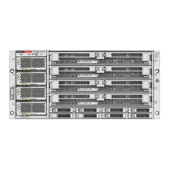
Front and Back Features and Components “Front Features and Components” on page 13 ■ “Back Features and Components” on page 14 ■ Front Features and Components 5-2M 5-2M 5-2M 5-2M 5-2M 5-2M 5-2M 5-2M HDD4 HDD5 HDD6 HDD7 HDD0 HDD1 HDD2 HDD3... -
Page 14: Back Features And Components
Back Features and Components To find the chassis serial number, see “How to Find the Server’s Serial Number” on Note – page 107. Figure Legend Locate button/LED (white) Over temperature LED (amber) Service Action Required LED Power supplies (PS0 through PS3) (amber) Power/OK LED (green) Hard drives (HDD0 through HDD7) - Page 15 Back Features and Components NEM0 NEM1 EM3.1 EM3.0 EM2.1 EM2.0 EM1.1 EM1.0 EM0.1 EM0.0 AC0 AC1 AC2 AC3 Figure Legend Fan modules (FM0 through Service processor module (SP). FM3). The SP provides I/O connectors for system management. See “Attaching Administration (SP) Cables” on page 97 for details.
-
Page 17: Unpacking The Server And Identifying The Rack Mounting Hardware
Unpacking the Server and Identifying the Rack Mounting Hardware This section provides procedures for unpacking the server and identifying the rack mounting hardware. To identify the rack mounting hardware and the correct rack mounting instructions, see ■ “How to Identify Your Rack Mounting Kit” on page To unpack your server, see “How to Unpack the Server”... - Page 18 Unpacking the Server and Identifying the Rack Mounting Hardware Legend Description Adapter bracket for round-hole racks in “How to Install the Universal Rack Mounting universal rack mounting kit Hardware in a Round-Hole Rack” on page 67 Adapter bracket for square-hole racks “How to Install the Universal Rack Mounting universal rack mounting kit Hardware in a Square-Hole Rack ”...
-
Page 19: How To Unpack The Server
Unpacking the Server and Identifying the Rack Mounting Hardware Legend Description Adapter bracket for round-hole racks in universal rack “Installing the Server in the Rack Using mounting kit the Universal Rack Mounting Kit” on page 47 Adapter bracket for square-hole racks universal rack mounting kit Front adapter bracket for standard rack mounting kit “Installing the Server In the Rack Using... - Page 20 Unpacking the Server and Identifying the Rack Mounting Hardware For rack mounting instructions, see one of the rack mounting sections as indicated in “How to Identify Your Rack Mounting Kit” on page Sun Server X2-8 (formerly Sun Fire X4800 M2) Installation Guide • August 2013...
- Page 21 Unpacking the Server and Identifying the Rack Mounting Hardware Legend Description Accessory tray, which contains rack mounting kit, shipping brackets, and other items Rack mounting kit Packaging foam inserts Server Pallet “How to Identify Your Rack Mounting Kit” on page 17 See Also...
-
Page 23: Installing The Server In The Rack Using The Standard Rack Mounting Kit
Installing the Server In the Rack Using the Standard Rack Mounting Kit This topic describes how to install your server in a rack using the standard rack mounting hardware. If you are not certain whether you have the standard rack mounting kit or the universal rack mounting kit, see “How to Identify Your Rack Mounting Kit”... -
Page 24: Tools And Staff Required
Tools and Staff Required Tools and Staff Required The server weighs about 180 pounds (100 kg) when fully loaded with components. To Caution – reduce the risk of serious personal injury or equipment damage, use a mechanical lift to install the server into the rack. -
Page 25: Compatible Racks
Contents of the Standard Rack Mounting Kit Compatible Racks The rack mounting hardware is compatible with a wide range of equipment racks that meet the following standards: Four-post rack (mounting at both front and rear). ■ Two-post racks are not compatible. Note –... - Page 26 Contents of the Standard Rack Mounting Kit Figure Legend 1, 2 Left (1) and right (2) shelf rails Once the front and rear adapter brackets are installed on the rack, the shelf rails drop into place. The hooks on the front and rear rails hook into the slots on the adapter brackets.
-
Page 27: Location Of The Rack Mounting Kit And The Shipping Bracket Kit
Location of the Rack Mounting Kit and the Shipping Bracket Kit Figure Legend Rear adapter brackets (1 pair) These attach to the rack and support the shelf rails. M6 cage nuts Used to adapt the rear adapter bracket to the back of square-hole racks. -
Page 28: Installing The Server In A Rack Using The Standard Rack Mounting Kit
Installing the Server In a Rack Using the Standard Rack Mounting Kit Legend Description Shipping brackets Installing the Server In a Rack Using the Standard Rack Mounting Kit This section provides instructions for installing your server in a rack. It includes: “How to Remove Components to Reduce Weight”... - Page 29 Installing the Server In a Rack Using the Standard Rack Mounting Kit To prevent system failure, you must return CPU modules to their original locations. Caution – Mark CPU module slot locations carefully before removing them from the chassis. Remove the CPU modules from the front of the chassis. The chassis contains four CPU module slots;...
- Page 30 Installing the Server In a Rack Using the Standard Rack Mounting Kit c. Gently slide the module forward until it is clear of the chassis (3). The CPU module is heavy. Use two hands. Caution – d. Close the ejectors on the CPU module. e.
- Page 31 Installing the Server In a Rack Using the Standard Rack Mounting Kit Do not insert forks from a lift device into these open bays, as this causes severe and Caution – non-repairable damage. a. Mark all PCIe EM cards with their slot locations. To prevent system failure, you must return PCIe EM cards to their original Caution –...
- Page 32 Installing the Server In a Rack Using the Standard Rack Mounting Kit “How to Replace the Components in the Server” on page 32 See Also ▼ How to Replace the Components in the Server The procedure “How to Remove Components to Reduce Weight” on page 28 describes how to remove components from the server.
- Page 33 Installing the Server In a Rack Using the Standard Rack Mounting Kit All CPU modules and PCIe EM modules must be returned to their original locations. Caution – Failure to do so can result in system failure. ▼ How to Install the Standard Rack Mounting Hardware in a Rack The rack mounting hardware consists of front and rear adapter brackets with cage nuts, screws, and shelf rails.
- Page 34 Installing the Server In a Rack Using the Standard Rack Mounting Kit The following figure shows the front adapter brackets being attached to a square-hole rack (1) and a round-hole rack (2). If your rack has round holes, use two screws each (1) to fasten the two rear adapter brackets (2) to the rack.
- Page 35 Installing the Server In a Rack Using the Standard Rack Mounting Kit The top of the rear bracket should sit 1 RU (three holes) lower than the top of the front bracket. If your rack has square holes: a. Insert the cage nuts (1) for the rear adapter brackets in the holes on the rack. The top of the rear bracket should sit 1 RU (three holes) lower than the top of the front bracket.
- Page 36 Installing the Server In a Rack Using the Standard Rack Mounting Kit c. Use two screws (3) to fasten each rear adapter bracket (4) to the rack. Place the shelf rails into the rack. The following figure shows a square-hole rack. The shelf rails expand (1) to fit the rack, then slip into the slots on the adapter brackets (2), and drop into place (3).
- Page 37 Installing the Server In a Rack Using the Standard Rack Mounting Kit “How to Insert the Server Into the Rack” on page 37 Next Steps ▼ How to Insert the Server Into the Rack The following procedure explains how to insert the server into the rack and on to the shelf rail assemblies on the rack.
- Page 38 Installing the Server In a Rack Using the Standard Rack Mounting Kit Perform the steps in “How to Install the Standard Rack Mounting Hardware in a Rack” on Before You Begin page Lift the server to its position on the rack. The use of a lift is recommended.
- Page 39 Installing the Server In a Rack Using the Standard Rack Mounting Kit 12” (304mm)
- Page 40 Installing the Server In a Rack Using the Standard Rack Mounting Kit Use four screws to attach the front of the server to the front of the rack. Use either the M6 x 25, or the 10-32 x 1 screws. On a threaded rack, use four M6 x 25, or four 10-32 x 1 screws.
-
Page 41: Removing And Installing The Standard Rack Mounting Kit Shipping Brackets
Removing and Installing the Standard Rack Mounting Kit Shipping Brackets Removing and Installing the Standard Rack Mounting Kit Shipping Brackets If the server is shipped in a rack, it must be supported by shipping brackets. If the server is shipped to you in a rack, you must remove the shipping brackets before ■... - Page 42 Removing and Installing the Standard Rack Mounting Kit Shipping Brackets Remove the four screws (1) that fasten the front shipping bracket (2) to the front of the server and remove it. The front shipping bracket contains eight threaded holes used for storing unused screws (four M6 and four 10–32).
- Page 43 Removing and Installing the Standard Rack Mounting Kit Shipping Brackets Remove the four screws (3) that fasten the rear bottom shipping bracket (4) under the back of the server and remove it. ▼ How to Install the Standard Rack Mounting Kit Shipping Brackets This procedure describes how to install brackets into a system equipped with the standard rack mounting kit.
- Page 44 Removing and Installing the Standard Rack Mounting Kit Shipping Brackets Figure Legend Front shipping bracket 2, 3 Two sets of screws (M6 and 10-32). Each set contains four screws for the front shipping bracket (2) and eight screws for the rear shipping brackets (5 and 6) Eight M6 cage nuts for rear shipping bracket in square-hole racks Top rear shipping bracket Bottom rear shipping bracket...
- Page 45 Removing and Installing the Standard Rack Mounting Kit Shipping Brackets Use the four long screws (M6 or 10–32) (1) to fasten the shipping bracket (2) to the front of the server. Insert the short screws into the four empty storage holes on the shipping bracket. They will be stored there to be used when you remove the shipping bracket.
- Page 46 Removing and Installing the Standard Rack Mounting Kit Shipping Brackets b. Reinstall the adapter brackets and the server, and install the rear shipping bracket cage nuts as you install the rear adapter brackets. This is included in the rack mounting procedure. “How to Install the Standard Rack Mounting Hardware in a Rack”...
-
Page 47: Installing The Server In The Rack Using The Universal Rack Mounting Kit
Installing the Server in the Rack Using the Universal Rack Mounting Kit This section describes how to install your server in a rack using the universal rack mounting hardware. If you are not certain whether you have the standard rack mounting kit or the universal rack mounting kit, see “How to Identify Your Rack Mounting Kit”... -
Page 48: Tools And Staff Required
Tools and Staff Required Tools and Staff Required The server weighs about 180 pounds (100 kg) when fully loaded with components. To Caution – reduce the risk of serious personal injury or equipment damage, use a mechanical lift to install the server into the rack. -
Page 49: Compatible Racks
Contents of the Universal Rack Mounting Kit Compatible Racks The rack mounting hardware is compatible with a wide range of equipment racks that meet the following standards: Four-post rack (mounting at both front and rear). ■ Two-post racks are not compatible. Note –... - Page 50 Contents of the Universal Rack Mounting Kit Figure Legend Top rear braces These attach to the posts at the upper back of the server. 2, 3 Left (2) and right (3) shelf rails Once the front and rear adapter brackets are installed on the rack, the shelf rails drop into place.
-
Page 51: Installing The Server In A Rack Using The Universal Rack Mounting Kit
Installing the Server in a Rack Using the Universal Rack Mounting Kit Figure Legend An assortment of M6 and 10-32 Oracle provides extra screws to support different screws configurations. Unused hardware can be discarded or recycled when you have completed the installation. The screws are packaged by size and type. - Page 52 Installing the Server in a Rack Using the Universal Rack Mounting Kit Before You Begin Circuit boards and hard drives contain electronic components that are extremely Caution – sensitive to static electricity. Ordinary amounts of static electricity from clothing or the work environment can destroy the components located on these devices.
- Page 53 Installing the Server in a Rack Using the Universal Rack Mounting Kit For each CPU module: a. Pinch the green tabs to release the ejectors (1). b. Pull both ejectors out to release the module (2). When the module is partway out of the chassis, close the ejectors, and grasp the Caution –...
- Page 54 Installing the Server in a Rack Using the Universal Rack Mounting Kit Remove the four power supplies from the front of the chassis. a. Pinch the handle to release the lever (1). b. Pull the lever to release the power supply (2). c.
- Page 55 Installing the Server in a Rack Using the Universal Rack Mounting Kit a. Mark all PCIe EM cards with their slot locations. To prevent system failure, you must return PCIe EM cards to their original Caution – locations. Mark PCIe EM slot locations carefully before removing them from the chassis. b.
- Page 56 Installing the Server in a Rack Using the Universal Rack Mounting Kit “How to Install the Universal Rack Mounting Hardware in a Square-Hole Rack ” on page 57 See Also “How to Install the Universal Rack Mounting Hardware in a Round-Hole Rack” on page 67 “How to Replace the Components in the Server”...
- Page 57 Installing the Server in a Rack Using the Universal Rack Mounting Kit All CPU modules (CMODs) and PCIe EM modules must be returned to their original Caution – locations. Failure to do so can result in system failure. When you reseat the CMODs, simultaneously push both handles past the locks, until they Note –...
- Page 58 Installing the Server in a Rack Using the Universal Rack Mounting Kit Verify that you have a 5RU space in your rack. Select the set of adapter brackets for square-hole racks. The server ships with two sets of adapter brackets: one for racks with square holes (1) and one for racks with round holes (2).
- Page 59 Installing the Server in a Rack Using the Universal Rack Mounting Kit...
- Page 60 Installing the Server in a Rack Using the Universal Rack Mounting Kit Attach the brackets to the front posts. Place the brackets so that the bottom of the bracket is aligned with the bottom of the (5RU) space where the server will go, and that the arrow labeled “Top” points up. The accessory tray includes a printed template that you can use to help align the adapter Note –...
- Page 61 Installing the Server in a Rack Using the Universal Rack Mounting Kit Use three M6 X 12 screws per side (1) to fasten the bracket (2) to the posts (3). Attach upper rear braces (1) to the rack posts (2) directly above the adapter brackets, as shown in the following figure.
- Page 62 Installing the Server in a Rack Using the Universal Rack Mounting Kit Before tightening the screws, slide the braces (1) up as far as they will go. The holes on the braces are oval shaped so they can move a little up and down when the screws are loose. Sun Server X2-8 (formerly Sun Fire X4800 M2) Installation Guide •...
- Page 63 Installing the Server in a Rack Using the Universal Rack Mounting Kit Remove the six screws (1) that hold the left and right shelf extenders (2) on the shelf rails (3), and then remove the shelf extenders. You must remove the shelf extenders before installing the server in the rack. They are used for other products.
- Page 64 Installing the Server in a Rack Using the Universal Rack Mounting Kit Place the shelf rails into the rack. The shelf rails expand (1) to fit the rack, then slip into the slots on the adapter brackets (2), and drop into place (3). Be certain to place the shelf rails in the proper orientation.
- Page 65 Installing the Server in a Rack Using the Universal Rack Mounting Kit...
- Page 66 Installing the Server in a Rack Using the Universal Rack Mounting Kit Thread the four M4 X 10 flathead locking screws (1) into the adapter brackets. These prevent the shelf rails from accidentally lifting out of the adapter brackets. Sun Server X2-8 (formerly Sun Fire X4800 M2) Installation Guide • August 2013...
- Page 67 Installing the Server in a Rack Using the Universal Rack Mounting Kit “How to Insert the Server Into the Rack” on page 77 Next Steps ▼ How to Install the Universal Rack Mounting Hardware in a Round-Hole Rack The rack mounting kit consists of adapter brackets, rear braces, shelf rails, cage nuts, and screws.
- Page 68 Installing the Server in a Rack Using the Universal Rack Mounting Kit Arrows on the adapter brackets (3) indicate how they should be oriented. Be sure to Note – install all brackets with the “Top” arrow (3) pointing up. Sun Server X2-8 (formerly Sun Fire X4800 M2) Installation Guide • August 2013...
- Page 69 Installing the Server in a Rack Using the Universal Rack Mounting Kit...
- Page 70 Installing the Server in a Rack Using the Universal Rack Mounting Kit Attach the adapter brackets to the front posts. Place the adapter brackets so that the bottom of the adapter bracket is aligned with the bottom of the (5RU) space where the server will go, and that the arrow labeled “Top” points up. Use three M6 x 12 or 10-32 x 10 shoulder screws for each side.
- Page 71 Installing the Server in a Rack Using the Universal Rack Mounting Kit Attach upper rear braces (1) to the rack posts (2) directly above the adapter brackets, as shown in the following figure. Use either two M6 x 12 or two 10-32 x 10 screws (3) per side.
- Page 72 Installing the Server in a Rack Using the Universal Rack Mounting Kit Before tightening the screws, slide the braces (1) up as far as they will go. The holes on the braces are oval shaped so they can move a little up and down when the screws are loose. Sun Server X2-8 (formerly Sun Fire X4800 M2) Installation Guide •...
- Page 73 Installing the Server in a Rack Using the Universal Rack Mounting Kit Remove the six screws (1) that hold the left and right shelf extenders (2) on the shelf rails (3), and then remove the shelf extenders. You must remove the shelf extenders before installing the server in the rack. They are used for other products.
- Page 74 Installing the Server in a Rack Using the Universal Rack Mounting Kit Place the shelf rails into the rack. The shelf rails expand (1) to fit the rack, then slip into the slots on the adapter brackets (2), and drop into place (3). Be certain to place the shelf rails in the proper orientation.
- Page 75 Installing the Server in a Rack Using the Universal Rack Mounting Kit...
- Page 76 Installing the Server in a Rack Using the Universal Rack Mounting Kit Thread the four M4 X 10 flathead locking screws (1) into the adapter brackets. These prevent the shelf rails from accidentally lifting out of the adapter brackets. Sun Server X2-8 (formerly Sun Fire X4800 M2) Installation Guide • August 2013...
- Page 77 Installing the Server in a Rack Using the Universal Rack Mounting Kit “How to Insert the Server Into the Rack” on page 77 Next Steps ▼ How to Insert the Server Into the Rack Perform the steps in “How to Install the Universal Rack Mounting Hardware in a Square-Hole Before You Begin Rack ”...
- Page 78 Installing the Server in a Rack Using the Universal Rack Mounting Kit 12” (304mm) Sun Server X2-8 (formerly Sun Fire X4800 M2) Installation Guide • August 2013...
- Page 79 Installing the Server in a Rack Using the Universal Rack Mounting Kit Use four screws to attach the front bezel of the server to the front of the rack, as shown in the following figure. For square-hole racks, use four M6 x 16 screws. ■...
- Page 80 Installing the Server in a Rack Using the Universal Rack Mounting Kit Sun Server X2-8 (formerly Sun Fire X4800 M2) Installation Guide • August 2013...
-
Page 81: Installing And Removing The Universal Shipping Brackets
Installing and Removing the Universal Shipping Brackets If you removed components from the server, replace them after the server is mounted in the rack. See “How to Replace the Components in the Server”on page “How to Remove the Server from the Rack” on page 91 See Also ■... - Page 82 Installing and Removing the Universal Shipping Brackets Figure Legend Front shipping bracket. Screws and cage nuts. The kit contains two sets of screws (M6 and 10-32), plus cage nuts. The cage nuts are not used for the Sun Server X2-8. Bottom rear shipping bracket.
- Page 83 Installing and Removing the Universal Shipping Brackets The front shipping bracket includes eight threaded holes (3) used for storing unused Note – screws. When the shipping brackets are not installed, the bracket holds the long screws used to install them. When the shipping brackets are installed, it stores the short screws that were used before the shipping brackets were installed.
- Page 84 Installing and Removing the Universal Shipping Brackets Insert the rear bottom bracket (1) under the back of the server with the side panels facing up, as shown in the following figure. Use four screws (2) to fasten it to the rack. Do not finish tightening these screws. They should be tight enough to hold the bracket in place, but you should still be able to move the bracket slightly.
- Page 85 Installing and Removing the Universal Shipping Brackets The bracket should be fastened to the posts, but loose enough to move slightly. Push the bracket up so that it rests firmly against the bottom of the server, and then finish tightening the screws that hold the bracket in place. If necessary, loosen the screws enough so that you can move the bracket, and then tighten them after pushing it against the bottom of the server.
- Page 86 Installing and Removing the Universal Shipping Brackets Figure Legend Front shipping bracket. Screws and cage nuts. The kit contains two sets of screws (M6 and 10-32), plus cage nuts. The cage nuts are not used for the Sun Server X2-8. Bottom rear shipping bracket.
- Page 87 Installing and Removing the Universal Shipping Brackets Remove the two screws (1) that fasten the front bracket (2) to the front of the server and remove...
- Page 88 Installing and Removing the Universal Shipping Brackets Find the screws from the front of shipping bracket that match your rack and use them to fasten the bezel into the rack. The front shipping bracket contains eight threaded holes used for storing unused screws (four M6 and four 10-32).
- Page 89 Installing and Removing the Universal Shipping Brackets Remove the four screws (1) that fasten the rear bottom bracket (2) under the back of the server and remove it. Replace the four screws that you removed in Step 4.
-
Page 91: Removing The Server From The Rack
Removing the Server from the Rack This section provides instructions for removing your server from a the rack. “How to Remove the Server from the Rack” on page 91 ■ “How to Remove the Rackmounting Hardware from the Rack” on page 94 ■... - Page 92 Removing the Server from the Rack Remove the four screws from the front bezel of the system. Using two hands, slide the server toward yourself and remove it from the shelf rails. Drop hazard. You must support the weight of the server before it is within 6 inches Caution –...
- Page 93 Removing the Server from the Rack 12” (304mm)
-
Page 94: How To Remove The Rackmounting Hardware From The Rack
Removing the Server from the Rack “How to Insert the Server Into the Rack” on page 77 See Also ▼ How to Remove the Rackmounting Hardware from the Rack This task shows how to remove the rack mounting hardware from the universal rack and from the standard rack. - Page 95 Removing the Server from the Rack Remove the screws that hold the adapter brackets (3 and 4) in place, and remove the brackets. The universal rack mounting kit is shown. The standard rack mounting kit is similar, but slightly different.
- Page 96 Removing the Server from the Rack Remove the screws (1) that hold the rear braces (2) in place, and remove the braces. Perform this step for the universal rack mounting kit only. The standard rack mounting kit does not include these braces. Sun Server X2-8 (formerly Sun Fire X4800 M2) Installation Guide •...
-
Page 97: Cabling And Power
Cabling and Power This section describes how to attach cables to the server and how to power the server on and off. “Attaching Administration (SP) Cables” on page 97 ■ “Cabling NEMs and PCIe EMs” on page 101 ■ “Powering the Server On and Off” on page 103 ■... - Page 98 Attaching Administration (SP) Cables Figure Legend Connect an Ethernet cable between the NET MGT port and the network to which future connections to the SP will be made. NET MGT port 0 is the suggested default. Connect a serial cable between the SER MGT port and a terminal device or a PC. You might need an adapter.
- Page 99 Attaching Administration (SP) Cables Figure Legend Video console Serial console USB (2 connectors)
- Page 100 Attaching Administration (SP) Cables SP Connectors FIGURE 1 CHASSIS Figure Legend Net management ports 0 and 1 Serial management Fault LED Power/OK LED Temperature LED Multiport cable connector Locate button/LED SP OK LED Sun Server X2-8 (formerly Sun Fire X4800 M2) Installation Guide • August 2013...
-
Page 101: Cabling Nems And Pcie Ems
Cabling NEMs and PCIe EMs Cabling NEMs and PCIe EMs Network express modules (NEMs) and PCIe express modules (PCIe EMs) provide connections that are used for non administrative purposes. NEMs provide 1 GbE and 10 GbE connectors. ■ The SAS connectors on the NEMs are unsupported. Note –... - Page 102 Cabling NEMs and PCIe EMs Figure Legend NEMs (two shown) EM slots with PCIe EMs Sun Server X2-8 (formerly Sun Fire X4800 M2) Installation Guide • August 2013...
-
Page 103: Powering The Server On And Off
Powering the Server On and Off Powering the Server On and Off The server has two power modes: standby and full power. The server enters standby power mode automatically when it is connected to AC power. ■ This provides power for the SP. See “How to Apply Standby Power for Initial Service Processor Configuration”... - Page 104 Powering the Server On and Off ▼ How to Power On All Server Components This procedure powers on all server components and is different from applying standby power, which powers on the service processor only. Verify that power cords have been connected and that standby power is on. In standby power mode, the Power/OK LED on the front panel blinks.
- Page 105 Powering the Server On and Off Graceful shutdown: Press and release the recessed Power button in the upper left-hand ■ corner of the front panel. This causes Advanced Configuration and Power Interface (ACPI)-enabled to perform an orderly shutdown of the operating system. Servers not running ACPI-enabled operating systems shut down to standby power mode immediately.
-
Page 107: Getting Service For Your Server
Getting Service for Your Server To get service for your server, find your server’s serial number, and contact Oracle Service through the following web site: http://www.oracle.com/us/support/index.html To find your server’s serial number, see “How to Find the Server’s Serial Number” on page 107. -
Page 109: Determining Your Server Management Strategy
Determining Your Server Management Strategy With your Oracle x86 server, you have three single-server management options available. They are: “Oracle Integrated Lights Out Manager” on page 110 ■ “Oracle Hardware Management Pack” on page 110 ■ “Oracle Hardware Installation Assistant” on page 111 ■... -
Page 110: Oracle Integrated Lights Out Manager
Oracle Integrated Lights Out Manager Oracle Integrated Lights Out Manager Oracle Integrated Lights Out Manager (ILOM) is system management firmware that is preinstalled on Oracle's x86-based servers and SPARC-based servers. The Oracle ILOM firmware automatically initializes as soon as power is applied to your server. Oracle ILOM enables you to actively manage and monitor components installed in your server. -
Page 111: Oracle Hardware Installation Assistant
Oracle Hardware Installation Assistant The Oracle Hardware Installation Assistant application is a provisioning tool for Sun Fire ■ and Sun Blade x86 servers. The application guides you through server setup and maintenance by providing a single interface that facilitates server installation, configuration, maintenance, and recovery tasks. -
Page 113: Configuring The Preinstalled Solaris Operating System
Configuring the Preinstalled Solaris Operating System This section describes how to configure the optional preinstalled Oracle Solaris operating system. Before proceeding, you must configure Oracle ILOM as described in “Communicating With Oracle ILOM and the System Console” on page 135. If your server is equipped with the optional preinstalled Oracle VM OS, see “Configuring Note –... -
Page 114: Configuring The Preinstalled Oracle Solaris Os
Configuring the Preinstalled Oracle Solaris OS Configuring the Preinstalled Oracle Solaris OS If you are connected to a monitor, when you boot the system, after the POST messages, a Note – prompt asks if you wish to view graphic output. Select graphic output to continue viewing boot messages on the monitor. - Page 115 Installation Worksheet Installation Worksheet (Continued) TABLE 1 Information for Your Answers: Asterisk (*) Installation Description or Example identifies defaults. Subnet If you are not using DHCP, is the system 255.255.0.0* part of a subnet? If yes, what is the netmask of the subnet? Example: 255.255.0.0 IPv6 Do you want to enable IPv6 on this...
- Page 116 Installation Worksheet Installation Worksheet (Continued) TABLE 1 Information for Your Answers: Asterisk (*) Installation Description or Example identifies defaults. LDAP Provide the following information about your LDAP profile: Profile name: Profile server: If you specify a proxy credential level in your LDAP profile, gather the following: Proxy-Bind Distinguished Name: Proxy-Bind Password:...
-
Page 117: How To Connect To The Server Using The Server's Ip Address
Installation Worksheet Installation Worksheet (Continued) TABLE 1 Information for Your Answers: Asterisk (*) Installation Description or Example identifies defaults. Time zone How do you want to specify your default ■ Geographic region* time zone? ■ Offset from GM ■ Time zone file Root password Choose a root password for the system. -
Page 118: (Optional) How To Redirect The Console Output To The Video Port
Installation Worksheet Start the Oracle ILOM console mode by typing the following: start /SP/console If you have changed the default SP serial port settings, make sure you reset them to the Note – default settings. Only accounts with Administrator privileges are enabled to configure the SP serial port. See the Oracle ILOM 3.0 documentation. -
Page 119: How To Connect To The Server Using A Serial Capture Program
Installation Worksheet ▼ How to Connect to the Server Using a Serial Capture Program Use a cable to connect the serial port of the server to the serial port of the serial capture host system. Make sure the communication properties of the serial port of the system are set to the defaults. The default settings are 9600 baud, 8N1 (eight data bits, no parity, one stop bit), disable flow control. -
Page 120: Oracle Solaris Os Information Products And Training
Oracle Solaris OS Information Products and Training For the Solaris 10 OS: Oracle Solaris 10 8/11 Information Library ■ For the Solaris 11 OS: Oracle Solaris 11 Information Library ■ Oracle Solaris OS Information Products and Training Sun provides flexible training options that accommodate your personal schedule and learning style. -
Page 121: Configuring The Preinstalled Oracle Linux Operating System
Configuring the Preinstalled Oracle Linux Operating System If you purchased an optional preinstalled Oracle Linux OS image on your server, finish the installation by configuring the preinstalled software. The preinstalled OS image contains all of the necessary drivers for your server model. The following lists the tasks necessary for configuring the preinstalled Oracle Linux OS. -
Page 122: Configure The Preinstalled Oracle Linux Os
Oracle Linux Configuration Worksheet Required Installation Information Description Your Answers Network configuration (if you are Supply the IP address for the not using DHCP) server. Example: 172.16.9.1 If the server is part of a subnet, supply the netmask of the subnet. Example: 255.255.0.0 If the server is accessed through a gateway, supply the IP address of... - Page 123 Oracle Linux Configuration Worksheet To restart the server, use one of the following methods: ■ From the Oracle ILOM web interface, click Host Management > Power Control, and then ■ select Reset from the menu. From the ILOM CLI, type: ■...
-
Page 124: Register And Update Your Oracle Linux Os
Oracle Linux Configuration Worksheet The Red Hat Compatible Kernel. For example: ■ Oracle Linux Server (2.6.32-279.el6.x86_64) Oracle recommends the use of Oracle Linux with the Unbreakable Enterprise Kernel for Note – all enterprise applications. Once an installation option has been selected, Linux starts. When done, you will see the Linux system login. -
Page 125: Related Information
Oracle Linux Configuration Worksheet If you don't already have one, create your ULN account. You will use your email address and CSI and you will be required to create a password. In the future, you will then simply use your email address and password to login to ULN. -
Page 127: Configuring The Preinstalled Oracle Vm Software
Configuring the Preinstalled Oracle VM Software This section contains the steps for configuring the optional preinstalled Oracle VM software. This section includes the following topics: “How to Configure Oracle VM” on page 127 ■ “Configuration Worksheets” on page 130 ■ “Getting Started With Oracle VM”... - Page 128 Configuring the Preinstalled Oracle VM Software At the Oracle ILOM prompt, type the following command and answer the prompt: -> start /SP/console Are you sure you want to start /SP/console (y/n)? y Serial console started. Watch the output and wait for the following message: ->...
- Page 129 Configuring the Preinstalled Oracle VM Software To display output to the video port, select the third option on the list and press Enter: ■ Oracle VM Server - ovs (xen-64-3.4.0 2.6.18-128.2.1.4.25.eI5ovs) If you choose this option, you must connect a device to the video connector on the server. To display output to the serial port, select the fourth option on the list and press Enter: ■...
-
Page 130: Configuration Worksheets
Configuration Worksheets Configuration Worksheets Before you begin configuring the Oracle VM software, use the worksheets in this section to gather the information you will need. “Oracle VM Server Configuration Worksheet” on page 130 ■ “Oracle VM Manager Configuration Worksheet” on page 131 ■... - Page 131 Oracle VM Manager Configuration Worksheet Oracle VM Manager Configuration Worksheet The Oracle VM software factory installed on your server includes optional Oracle Linux VM Manager software. If you already have an Oracle VM Manager installed on your network, it is not necessary to deploy the Oracle Linux VM Manager, since you can register the new Oracle VM Server to the existing VM Manager.
-
Page 132: Getting Started With Oracle Vm
Getting Started With Oracle VM Worksheet for Oracle VM Manager Configuration (Continued) TABLE 3 Information for Configuration Description or Example Your Answers Oracle VM Manager Database Choose a password for the database account; passwords account there are no restrictions on the characters or length. - Page 133 Getting Started With Oracle VM ▼ How to Configure the VM Network Interfaces Either two or three of the following VMs are available on the server as part of the factory-installed software configuration process: Oracle Solaris ■ Oracle Linux ■ Oracle VM Manager (installed only if you selected it during the installation procedure) ■...
- Page 134 Oracle VM Passwords To configure the VM network interfaces, select the interface and click Edit. Configure the interface accordingly. For Oracle Solaris VM, add the bridge to the configuration file. Change the vif parameter in /OVS/running_pool/OVM_SOLARISnnnn/vm.cfg (where nnnn is the Oracle Solaris version, for example 10U8).
-
Page 135: Communicating With Oracle Ilom And The System Console
Communicating With Oracle ILOM and the System Console These topics provide instructions for connecting to the Oracle Integrated Lights Out Manager service processor (SP), and the system console. “Server Connections” on page 135 ■ “About Oracle ILOM SP IP Addresses and the Oracle ILOM Interfaces” on page 135 ■... -
Page 136: Determining The Sp Ip Address
Determining the SP IP Address Determining the SP IP Address You need to determine the service processor (SP) IP (network) address to use the SP Integrated Lights Out Manager (Oracle ILOM) to manage the server. You can determine the IP address using either one of these ways: “How to Get the SP IP Address by Using the BIOS Setup Utility”... -
Page 137: Connecting To Oracle Ilom
Connecting to Oracle ILOM -> To display the SP IP address, type: show /SP/network Targets: test Properties: commitpending = (Cannot show property) dhcp_server_ip = 192.2.0.10 ipaddress = 192.2.0.163 ipdiscovery = DHCP ipgateway = 192.2.0.254 ipnetmask = 255.255.252.0 macaddress = 00:21:28:44:F4:EE pendingipaddress = 192.2.0.163 pendingipdiscovery = DHCP pendingipgateway = 192.2.0.254... - Page 138 Connecting to Oracle ILOM 9600 baud ■ Disable hardware flow control (CTS/RTS) ■ Disable software flow control (XON/XOFF) ■ Connect a serial cable from the SP SER MGT port to a terminal device. “Attaching Administration (SP) Cables” on page 97 for the location of the SER MGT port.
- Page 139 Connecting to Oracle ILOM Where user_name is the name of an existing Oracle ILOM user account and sp_ip_address is the server's service processor IP address. If this is the first time logging in to Oracle ILOM, you can use the default root account (root) . When prompted, enter your user password.
-
Page 140: Connecting To The System Console
Connecting to the System Console At the Oracle ILOM login page, enter an existing user account and password. If this is the first time logging in to Oracle ILOM, you can use the default account root and password changeme. To enable first-time login and access to Oracle ILOM, a default Administrator account Note –... - Page 141 Connecting to the System Console ▼ How to Connect to the Server Locally (Physical Console) If you plan to interact with the system console directly, make the connections described in this procedure. See “Attaching Administration (SP) Cables” on page 97 for the locations of the system connectors.
- Page 142 Connecting to the System Console If the remote console system is running Oracle Solaris OS, volume management must be ■ disabled for the remote console to access the physical floppy and CD/DVD-ROM drives. If the remote console system is running Windows, Internet Explorer Enhanced Security ■...
- Page 143 Connecting to the System Console The Oracle ILOM main screen appears. Click the Remote Control tab in the Oracle ILOM web interface. The Launch Redirection screen appears. Make sure that the mouse mode is set to Absolute mode in the Mouse Mode Settings tab. Note –...
- Page 144 Connecting to the System Console Click 8-bit color or 16-bit color, and then click Launch Redirection. When you are using a Windows system for remote console redirection, an additional Note – warning might appear after you click Launch Redirection. If the Hostname Mismatch dialog box is displayed, click the Yes button.
- Page 145 Connecting to the System Console From the Devices menu, select the appropriate item based on the delivery method you have chosen. Remote Physical Floppy Disk – Select Floppy to redirect the server to the physical floppy ■ drive attached to the remote console. Remote Floppy Image –...
-
Page 147: I/O And Interrupt Resource Allocation
I/O and Interrupt Resource Allocation The BIOS allocates I/O and interrupt resources when the system boots. If your system includes many I/O devices, it might not have enough of these resources for all of them. In this case, you can reconfigure the BIOS to allocate resources to specific devices. This section includes the following topics: “Option ROM and I/O Space Allocation”... -
Page 148: Sun Server X2-8 (Formerly Sun Fire X4800 M2) Installation Guide • August
Option ROM and I/O Space Allocation I/O Space Allocation The PC architecture provides a total of 64 Kbytes of I/O space. By default, the BIOS allocates I/O space as shown in the Default I/O Allocation table. The total available space appears in the Maximum Allocation column. ■... - Page 149 Option ROM and I/O Space Allocation It is possible that the device you added has been assigned option ROM and/or I/O space at the expense of some other device. If this is the case, the device you added does not appear in the list, but the original device does.
- Page 150 Option ROM and I/O Space Allocation Select Chipset. The Advanced Chipset Settings screen appears. Select North Bridge Configuration. The NorthBridge Chipset Configuration screen appears. Sun Server X2-8 (formerly Sun Fire X4800 M2) Installation Guide • August 2013...
- Page 151 Option ROM and I/O Space Allocation To configure option ROM: a. Select Option ROM Scan for PCIe Devices. The Option ROM Scan appears. b. Use this display to configure option ROM allocation as follows: Use the arrow keys to scroll down the list. ■...
-
Page 152: Allocating Msi Interrupt Space (Oracle Solaris Os Only)
Allocating MSI Interrupt Space (Oracle Solaris OS Only) To configure I/O space allocation: a. Select I/O Allocation for PCIe Devices. BIOS displays the I/O Allocation for all PCIe devices. b. Use this display to enable or disable devices as required. Enable any device you wish to boot from, and disable any device you do not wish to boot from. -
Page 153: How To Identify And Fix Interrupt Resource Shortages
Allocating MSI Interrupt Space (Oracle Solaris OS Only) ▼ How to Identify and Fix Interrupt Resource Shortages When you encounter a shortage of I/O interrupts on level 6, Oracle recommends that you assign one of the drivers to interrupt level 5 or 4. Interrupt level 5 is the first priority. - Page 154 Allocating MSI Interrupt Space (Oracle Solaris OS Only) Look at the messages in /var/adm/messages to identify the driver that requires more interrupts than are available. In this example, it is ixgbe. Once you have determined that some devices do not have interrupts, use the commands devfsadm -C and mdb -k to show which interrupts are assigned to a particular level.
- Page 155 Allocating MSI Interrupt Space (Oracle Solaris OS Only) 145 0x68 MSI-X 30 1 ixgbe_intr_msix 146 0x69 MSI-X 31 1 ixgbe_intr_msix 147 0x6a MSI-X 32 1 ixgbe_intr_msix 148 0x6b MSI-X 33 1 ixgbe_intr_msix 149 0x6c MSI-X 34 1 ixgbe_intr_msix 150 0x6d MSI-X 35 1 ixgbe_intr_msix 151 0x6e...
- Page 156 Allocating MSI Interrupt Space (Oracle Solaris OS Only) After reassigning the interrupts, to view the reassigned interrupts, run the mdb -k command. The following example shows the system from Step 3 after igb has been reassigned to interrupt level (IPL) 5. As a result, the system is able to assign 24 interrupts to ixgbe. # devfsadm -C # mdb -k Loading modules: [ unix krtld genunix specfs dtrace cpu.generic uppc pcplusmp ufs ip...
- Page 157 Allocating MSI Interrupt Space (Oracle Solaris OS Only) 154 0x69 MSI-X 77 1 ixgbe_intr_msix 155 0x49 MSI-X 78 1 igb_intr_tx_other 156 0x4a MSI-X 79 1 igb_intr_rx 157 0x6a MSI-X 80 1 ixgbe_intr_msix 158 0x6b MSI-X 81 1 ixgbe_intr_msix 159 0x4b MSI-X 82 1 igb_intr_tx_other 160 0xa0...
-
Page 159: Sun Server X2-8 Specifications
Sun Server X2-8 Specifications “Physical Specifications for the Sun Server X2-8” on page 159 ■ “Power Specifications for the Sun Server X2-8” on page 159 ■ “Environmental Specifications” on page 160 ■ “Acoustic Specifications” on page 160 ■ Physical Specifications for the Sun Server X2-8 Specification Value Height... -
Page 160: Environmental Specifications
Environmental Specifications Environmental Specifications Specification Value Temperature (operating) 41° to 90° F (5 ° to –32.2° C) Temperature (storage) –40° to 149° F Humidity 20% to 90% non-condensing Operating altitude 0 to 10,000 feet (0 to 3048 m) maximum Decrease operating temperature 1.8° F (1° C) per 985 feet (300 m) above 2955 feet (900 m) altitude Airflow Airflow typical (for room temperatures 73°... -
Page 161: Requesting Physical Media
Requesting Physical Media If you choose, you can access the latest software release through a physical media request (PMR), either online or on the telephone. “How to Request Physical Media Online” on page 161 ■ “How To Request Physical Media by Phone” on page 162 ■... -
Page 162: How To Request Physical Media By Phone
Requesting Physical Media Question Your Answer Are you requesting a required password for a patch download? Are you requesting a patch on CD/DVD? If requesting a patch on CD/DVD, please provide the Enter the patch number for each download that you patch number and OS/platform? want from the software release. - Page 163 Requesting Physical Media Call Oracle support, using the appropriate number from the Oracle Global Customer Support Contacts Directory: http://www.oracle.com/us/support/contact-068555.html Tell Oracle support that you want to make a physical media request (PMR) for the Sun Server X2–8. If you are able to access the specific software release and patch number information from My ■...
-
Page 165: Index
Index connecting (Continued) to Oracle ILOM CLI acoustic specifications, 160 using serial management port, 137–138 Advanced Configuration and Power Interface (ACPI), 104–105 to remote console, 141–145 allocating to serial console, 141 I/O space, 149–152 to the Oracle ILOM CLI MSI interrupt space, 153–157 using SSH, 138–139 option ROM, 149–152 to the Oracle ILOM web interface, 139–140... - Page 166 Index fan modules, 14 main power, 104 finding the serial number, 107 mechanical lift, 91–94 finding your product on My Oracle Support media request (support.oracle.com), 8 by phone, 162–163 firmware online, 161–162 updates MSI interrupt space, allocating, 153–157 requesting media, 161–163 multiport cable, 97 My Oracle Support, how to use, 8 graceful shutdown, 104–105...
- Page 167 Index physical media firmware, 161–163 serial console, connecting, 141 software, 161–163 serial management port physical media request connecting to Oracle ILOM CLI, 137–138 by phone, 162–163 connecting to the Oracle ILOM CLI, 136–137 online, 161–162 serial number, 107 physical specifications, 159 server power back panel, 97...
- Page 168 Index static electricity caution, 28–32, 51–56 support.oracle.com, 8 system console, connecting to, 141 tools required, 24, 48 training, Oracle Solaris OS, 120 universal rack mounting kit, 17–19 unpacking the server, 19–21 video port, 118 web Oracle ILOM interface, 139–140 weight, reducing, 28–32, 51–56 worksheet, Oracle Solaris OS, 114 Sun Server X2-8 (formerly Sun Fire X4800 M2) Installation Guide •...
Need help?
Do you have a question about the Sun X2-8 and is the answer not in the manual?
Questions and answers