
Related Manuals for SMC Networks raptor


Summary of Contents for SMC Networks raptor
- Page 1 Primary injection testing system User’s Guide Raptor Reference: KAXVMV02 Published: 9 April 2013 Version: 1...
- Page 2 Raptor Quality is the core of the business activity of EuroSMC, S.A., aimed at fully satisfying customer needs and expectations. LIMITATION OF LIABILITY EuroSMC, S.A. does not recognise any contractual link derived from the information set forth in this document, including the product features and technical data. The user is solely liable for the consequences of applying the product referenced in this document.
-
Page 3: Limited Warranty
Users Guide LIMITED WARRANTY This product is guaranteed against material and manufacturing defects of the product itself for a period of 12 months as from the registration date of the product. If this registration does not occur after 30 days as from the shipping date, the shipping date will be considered the start of the warranty period. - Page 4 Raptor...
-
Page 5: Table Of Contents
Standards applied ..................8 ELEMENTS COMPRISED IN THE SYSTEM ................9 SAFE USE OF THE EQUIPMENT ................... 11 Dangerous Situations ................11 Hazardous situations for the Raptor system ..........12 INTRODUCTION ......................... 13 LOCATION OF ELEMENTS ....................14 Raptor-MS (Control panel) ................ 16 Raptor-MS (Expansion panel) .............. - Page 6 Raptor AVAILABLE MEASUREMENTS ....................34 Internal measurements ................34 Hardware measurements ................. 34 Calculated Measurements ................ 37 Functions related to measurement ............38 OBTAINING THE TEST REPORTS ..................39 Concept of Report and Test............... 39 How to use the Reports and Tests............. 39 Using the RaptorSync programme (for PC with Windows) ......
- Page 7 Update control program of the Raptor-HH/M..........90 Update firmware of the Raptor-MS unit............91 Consult the Firmware versions of the Raptor-SL unit........91 Consult serial numbers of the units that make up the system......91 Adjust the Hardware meters ................. 91 PROBLEMS THAT MIGHT ARISE ...................
-
Page 8: Declaration Of Conformity
Raptor DECLARATION OF CONFORMITY For the Raptor system. Applicable to all elements comprised in the system. Raptor MS / Raptor SL / Raptor HH Manufacturer EuroSMC, S.A. Pol. Industrial P-29 C/Buril, 69 28400 Collado Villalba Madrid – Spain Declaration of Conformity... -
Page 9: Elements Comprised In The System
1 Ethernet cable, 2-m long 1 USB connection cable, 2-m long 1 universal power supply (100-240 VAC), with a 7.5-VDC output 1 stylus for touch screen 1 cable for connecting the Raptor-HH to the Raptor-MS, 3- m long 1 nylon protective cover... - Page 10 Raptor Raptor-MS 1 Raptor-MS Unit 1 power supply cable, 3-m long 1 cable for low-level measurement, 2-m long 2 pairs of connection cables (red-black), 2-m long 1 set of clips (red-black), medium, alligator type 1 set of 3 small clips, alligator type...
-
Page 11: Safe Use Of The Equipment
Users Guide SAFE USE OF THE EQUIPMENT Before using the equipment, you must carefully read this manual, especially this section, which refers to the safety precautions that must be observed. Symbols used Danger – It identifies actions and situations that represent risks to the user. -
Page 12: Hazardous Situations For The Raptor System
Hazardous situations for the Raptor system Caution – In systems with Raptor-SL units, when preparing to conduct injections by pass-through turns, be sure that all the units are powered. This is necessary so that the thermal protection systems work correctly. -
Page 13: Introduction
Raptor units as if they were a single unit and without having to connect them to each other, thereby reaching an injection power of over 18 kVA and a current of up to 15,000 amperes. -
Page 14: Location Of Elements
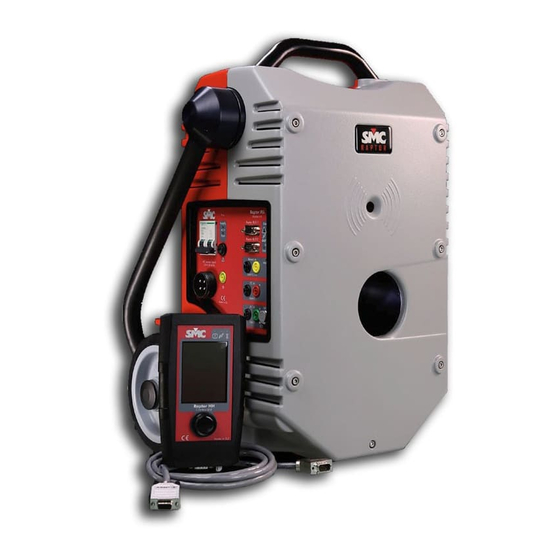
Raptor LOCATION OF ELEMENTS Rear Fold-down handle lock control. Infrared communications port Top structural handle Fold-down transport handle Control panel Hole for pass-through turn Rear Rear part of the equipment... - Page 15 Users Guide Front Infrared communications port Hole for pass-through turn Expansion panel Front Front part of the equipment Phase reference for the pass-through turn.
-
Page 16: Raptor-Ms (Control Panel)
Raptor Raptor-MS (Control panel) Power supply control Console and expansion connectors Status indicators Measurement inputs... -
Page 17: Raptor-Ms (Expansion Panel)
Users Guide Raptor-MS (Expansion panel) Voltage and current auxiliary output Expansion connector... -
Page 18: Raptor-Sl (Control Panel)
Raptor Raptor-SL (Control panel) Power supply control Status indicators... -
Page 19: Raptor-Hh
Users Guide Raptor-HH Top connection panel with USB, Ethernet and power input Touch panel Status and alarm LEDs Rotary and push button control Bottom connection panel and stylus slot... -
Page 20: How To Connect The System
Raptor-SL: 26 A permanently, 52 A for 3 minutes and 104 A for 3 seconds. You must keep in mind that the Raptor gives maximum power when fed at 240 VAC, measured at the start of the supplied power supply cable. To the extent that this voltage is less or drops during the test, the maximum current or maximum voltage will also drop. -
Page 21: Make The Connections
Connect the Console (Raptor-HH) to the Master case using the cable provided. Now connect the Raptor-MS and Raptor-SL units to the power supply. Do not make this connection permanent, due to the fact that if several units are combined, the system requires that all the units be connected with the same polarity. -
Page 22: Turning On The System
Raptor TURNING ON THE SYSTEM Raise the main switches of each one of the units forming your Raptor system. The correct polarity and power supply status can be checked through the indicators on the control panel of each unit. Green LED -> Right LED off ->... - Page 23 The one in the expansion panel indicates that the auxiliary output is active. In Raptor-SL unit, there are two but in this case indicate which of the two internal transformers are active. With the system stable, the identification window reports the detected system according to the number of units comprised in the system (Raptor-C05, Raptor-C15, etc.).
-
Page 24: An Initial View Of The Console
The power LED (red) will indicate the activity status of the output power. The connectivity LED (blue) indicates that the Raptor system has been detected and is stable when it is illuminated permanently. When this LED is flashing, it indicates that the... -
Page 25: Main Touch Screen
Measurements zone. The controls that show the measurements taken by the hardware equipment are located here. They can be measurements (direct readings made by the Raptor-MS) or calculated hardware measurements (processed based on meters). You can modify the meters you want to be displayed... - Page 26 Raptor at any time, although two of them (the time meter and the stop condition) are always visible. Meter selection. options To add or remove meters, tap on the button and then meters . A screen will be displayed where you can select the hardware and calculated meters.
- Page 27 Users Guide When Dry contact mode is assigned, if the voltage applied to the binary input exceeds 18-20 V DC the machine is protected changing mode automatically to Vmode high (15 V). Upon this protection, you are warned by alarm indicator overload but it is a momentary display, as when it changes to voltage mode, the alarm disappears.
-
Page 28: Injection Zone
Raptor Injection zone. This is where the controls and indicators related to power generation are located. Generation level This control is used to assign the level to be generated. To be able to modify the value, the control must be selected. To do so, tap on the control. - Page 29 Users Guide If generation is enabled, it is not possible to change any of the system’s settings. Pulse It changes the mode to control how generation is turned on and off. If it is active, when the dial is pressed and held, generation is produced, and it is turned off when the dial is released.
-
Page 30: Making The First Current Injection
Raptor System. The majority of the application’s controls open up a window, thereby allowing the controls to be configured by tapping twice on them. -
Page 31: Steps To Follow
Users Guide Steps to follow Select the pass-through turns. You must tell the system how many turns have been wound through the central hole. If this window is not displayed, you must proceed to step 2 and then return to this one. Select the injection mode and the measurement range. - Page 32 (~100 ms.) to detect the connected load and to be able to SELF- REGULATE. The Raptor System will not compute the times in these cases. Selecting the value.
- Page 33 Enabling injection. Tap on the button to enable injection. This function prevents the dial from being accidentally pressed. Important – With injection disabled, the Raptor System will not generate through its outputs. If it is enabled, other actions will be prohibited.
-
Page 34: Available Measurements
The main current meter is a Rogowsky type of sensor included in the Raptor-MS case, which surrounds the hole where the pass-through turns are inserted. Due to the characteristics of this sensor, it measures the total current flow passing through the system. - Page 35 Users Guide Eight ‘Hardware’ measurements are available: • High level external voltage measurement. (V2in) • External current measurement (A1in). • Low level external voltage measurement (V1in). • Phase measurement between V2in and A1in. • Phase measurement between V2in and V1in. •...
- Page 36 Raptor Measurement units Measured value Measurement input name If the value of the measurement is in blue, it indicates the automatic range setting. To select the ‘Hardware’ measurements, proceed as indicated in the figure. It can be seen in the image, that the ‘Hardware’...
-
Page 37: Calculated Measurements
Users Guide Calculated Measurements Based aforementioned Internal Hardware measurements, the calculated measurements are obtained through calculations. Up to 4 measurements are shown on each page. The number of pages of Calculated measurements will depend on how many have been selected. The current and total pages are shown in the lower right-hand corner. -
Page 38: Functions Related To Measurement
Raptor Functions related to measurement Hold button. After tapping on it, the values of the measurements maintained, both ‘Hardware’ ‘Calculated’ measurements, in addition to the values shown on the chronometer and the binary input. If it were already activated, by tapping on it, the meters would be released and the currently measured values would be shown. -
Page 39: Obtaining The Test Reports
Users Guide OBTAINING THE TEST REPORTS The Raptor system is equipped with the capacity to save the results of tests for subsequent review or for printing the test reports through the RaptorSync programme (for a PC). Concept of Report and Test. -
Page 40: Using The Raptorsync Programme (For Pc With Windows)
With your Raptor system, you will have received the RaptorSync application, an auxiliary feeder cable for the Raptor-HH console and a USB cable. This is all you need to view, import and print reports from a PC with the Windows operating system. - Page 41 Users Guide Preparing communication Once the ActiveSync programme is open, a screen similar to the following will open. (the screen may vary according to the installed version) From File menu, select Connection Settings… The following settings screen will be displayed: Since you are going to connect using a USB cable, it is not necessary to mark those settings that refer to the COM serial port.
- Page 42 Raptor At this screen, select ‘Files’ and click on ‘Next’. A message will be displayed, warning that a folder is going to be created on your desktop. Accept it. This screen, with the green icon to the right, indicates that you have successfully finished the connection...
- Page 43 When the Raptor-HH console is detected, the necessary Microsoft software for establishing communications will be downloaded automatically to your PC. After installation and restarting your PC, if required, upon connecting the Raptor-HH, you’ll see the following screen: You can close it.
-
Page 44: Information And Reports Of The Device
Raptor Running the RaptorSync programme Be sure that you have connected the Raptor-HH console, and click on the icon that will have appeared on the desktop. This screen will be displayed. Local database. List and Information and report viewer reports on the device Information and reports of the device. -
Page 45: Local Database
Users Guide Reports panel: it shows the list of reports that exist on the device. To display this panel, click on the arrows in the reports header: Three types of actions can be taken with the reports list: • Import. It imports the database from the device to a local database. It does not require confirmation to perform the action. - Page 46 Raptor Report display panel. It displays the report selected in the list of the local database. A Vc Magnetisation test and its graph can be seen in the following image.
-
Page 47: Other Possible Injections
Users Guide OTHER POSSIBLE INJECTIONS The Raptor-MS unit has auxiliary outputs to be able to inject small currents or high voltages that are essential in certain tests. If working with predesigned templates (see chapter “Management of predesigned templates”), this selection will be made automatically. -
Page 48: Anticipating The Current That Will Be Obtained
To make it easier to give a prior estimation of the current it will obtain, the Raptor system incorporates a powerful calculator as part of the Raptor-HH console control application. -
Page 49: The Results Of The Calculation
If you use the ultra-flexible type of cable that can be supplied as an option with the Raptor system, you must reduce this maximum by 10% as it is thicker than normal. The m/cable selector must be used to indicate the length of the cables to be used. The system uses this information to determine how many turns it can carry out and also the distance to load, apart from calculating the current. - Page 50 Raptor White background No cable cross-section warning Orange Warning that for the selected cross-section, the background current density may exceed the recommended maximum. These maximums depend on the work regime. Indicator ON The current will be limited by the system...
-
Page 51: Management Of The Pre-Designed Templates
Users Guide MANAGEMENT OF THE PRE-DESIGNED TEMPLATES The Raptor system can carry out a lot of tests thanks to its measurement inputs, on the one hand, and to its injection capacities, on the other hand. However, for these tests to be able to be carried out comfortably, quickly and error-free, there must be a basic method that is very easy for the operator to understand and apply. -
Page 52: Description Of Factory Templates
Description of Factory templates General The GENERAL templates permits selecting and controlling any output value, in any of the generators that the Raptor system possesses. This is the basic control mode of the equipment. This can be selected directly by pressing on the Options button. -
Page 53: Circuit Breaker
However, you must make sure that this connection between poles is carried out with minimum possible impedance as your Raptor configuration may be able to inject to one pole but not to all of them. -
Page 54: Overcurrent Relay
CT. In many cases it is highly recommendable to move the Raptor equipment close to the CT, using the people elevator buckets. -
Page 55: Current Transformer (Ct)
Users Guide Connections: Connect the output of the pass-through turn to each side of the CT Primary. The chronometer stop signal should be taken either from a OC Relay main contact of the circuit breaker or from the 52a auxiliary contact of the same circuit breaker. - Page 56 Raptor burden (cosine phi). The ratio must always be measured at a burden that must be known, as it varies with this. Template configuration: The template is configured as follows: • Generator: pass-through turn • Time display: As a timer in seconds (8 s, maximum duration of high current injection) •...
- Page 57 CT. It is advisable to do this at 120%, 100%, 50% and 20% of its nominal current. If it is a Protection CT it is more important to test the ratio at the highest possible points permitted by your RAPTOR system, apart from at 100%.
-
Page 58: Rogowski Ct
Raptor Rogowski CT Current Sensors or Transducers, based on the so-called Rogowski coil principle, are being used more and more frequently today. They are combined with electronics that condition their output, thus presenting a greater advantage over the traditional induction CT, in terms of the total absence of saturation, as they have no magnetic core. - Page 59 Users Guide equipment, follow the steps below: Connect the GREY coloured side of the RAPTOR to the input indicated as “Incoming current” of the Sensor. Connect the RED coloured side of the RAPTOR to the input indicated as “Outgoing current” of the Sensor.
-
Page 60: Low Power Ct
Raptor Low Power CT This template is identical to the one described above, so we refer to that for its use. Indeed, different systems have appeared on the market to carry out the same function as a classic CT, but with advantages over it (economic, size, lack of saturation, etc.) - Page 61 Users Guide • V1in input secondary voltage meter in Volts. Auto Mode (voltage drop between the points selected). • Phase angle meter between voltage V1in and primary current Io. • Power factor meter (cos phi) between V1 and Io. • Impedance (Z) meter between the selected points.
-
Page 62: Ground Grid
Raptor Ground grid This template permits testing the integrity of the grids and earth taps within a sub-station or power plant. It is very important to regularly check the integrity of the ground grid, and above all, of the connections from any... - Page 63 Users Guide Due to the distance between the two test points, the supplementary measurement cable that you will have to use for at least one of the test points will be long. To avoid noises, you must use a shielded cable which shield must be connected to the YELLOW tip of the equipment test cable.
-
Page 64: Ct Burden
Raptor CT Burden This template enables us to determine, very accurately, the burden that is connected in the secondary of a CT. Accurate knowledge of this value as well as of its power factor is very important to determine if the CT is suitable or not for this burden. - Page 65 S2. Make sure that they are firmly connected together. Connect the RED tap of the auxiliary output of the RAPTOR , using a test cable, directly to the GREEN tap of the current measurement input A1 of the actual equipment.
-
Page 66: Voltage-Based Ct
Raptor Test: Select and inject the right current value for the test, depending on the nominal secondary current value of the CT (1 or 5A ) The chronometer will start up and it will be possible to see the test results on the meter display. - Page 67 Users Guide • V2/V1 ratio meter which is shown as a result of the division between the two voltages. Connections: The Auxiliary Output Power Generator is Burden used in voltage mode to carry out this test, feeding the CT secondary, and the induced voltage is measured in the primary.
-
Page 68: Volt. Transformer (Vt)
Raptor Test: Select and inject the adequate test voltage level. It is advisable to inject the maximum voltage value considered to be safe for the insulation of the secondary winding of the transformer on one side, and that is not going to exceed the value in primary of 3 V, which is the maximum value that input V1in can measure. - Page 69 Users Guide Template configuration: The template is configured as follows: • Generator: Auxiliary power output. Voltage Mode • Time display: As chronometer in seconds. Stop mode: Push on dial • V1in input voltage meter in mVolts. Auto Mode (Voltage measurement in secondary of VT).
-
Page 70: Vt Burden
Raptor * The level of the measurement input V1 is very low so a cable with a special connector is used (supplied with the equipment) to shield the measurements well from possible electromagnetic noise. In ambients where there is loud noise, the tip of the YELLOW cable (Earth) must be connected to the earth of the system, or at least to the BLACK tip of the measurement cable. - Page 71 Users Guide Template configuration: The template is configured as follows: • Generator: Auxiliary power output. Voltage Mode • Time display: As chronometer in seconds. Stop mode: Push on dial • V2in input voltage meter in Volts. Auto Mode (voltage measurement injected into the burden).
-
Page 72: Short-Circuited Pt
Raptor Connect the BLACK bushing of the voltage measurement input V2 to the cable that is connected at point X2 of the VT. Warning – It is very important for you to make sure that the pass- through turn generator has no burden of any kind, either by extracting the cable from the inside, if there is one, or making sure that the turn is open, with no possibility of accidental closure. - Page 73 Users Guide Voltage expressed in % of the nominal primary voltage (High), necessary to obtain the nominal primary current of the transformer, with the secondary side (Low) short-circuited. Several tests are required, one per winding, on the one hand, to calculate these parameters, as well as an adequate calculation later on, using the results obtained in each one of them, and also considering the nominal technical characteristics of the PT (which are on the transformer plate) with respect to transformation ratio, connection...
- Page 74 Raptor Connect as follows (the connection between phases H1 and H2 is described, repeat this connection for phases H2H3 and for H3H1: Connect the BLACK bushing of the Auxiliary Output to H2 of the PT. Connect the RED bushing of the Auxiliary Output to the GREEN bushing of the current measurement input A1.
-
Page 75: Pt Ratio
Users Guide The Vccr value obtained must be lower than the available in the equipment , 230 V. If it is higher, replace Ired of the formula with a lower value until the Vccr value is less than 230 V. Once you know these values, connect the equipment output and gently adjust the output voltage until you obtain the value READ on display V2, equal to Vccr. - Page 76 Raptor Connections: The Auxiliary Output Power Generator is used in voltage mode to carry out this test, feeding between two phases or between phase and neutral, as possible, the High side of the relative voltage measured between the two bushings corresponding to the same phases on the Low side, which are being injected from the High side.
- Page 77 Users Guide Test: Connect the equipment output and gently adjust the output voltage until it is as high as possible (max. 230 V). You will be able to read all the values indicated by the meters during the injection. If the measurements are seen to be unstable, and their values are continuously changing, use the FILTER option to see the most stable values.
-
Page 78: Special Functions
Raptor SPECIAL FUNCTIONS The templates described above only generate a suitable configuration for a certain test. Apart from giving a configuration, the functions also carry out more complicated tests where the generation or stoppage values vary with time in a totally automated process. - Page 79 Users Guide Function configuration: Time of last Number of trip total trips Area where the Time elapsed opening and closing from the first times are shown. trip to the last. Fault current value Connections Connect the output of the Pass-through Turn Generator to the input and output of the Circuit Breaker of the recloser.
-
Page 80: Ct Magnetisation
Raptor CT Magnetisation This function permits the application of an increasing voltage in the secondary, with the primary open, until the current transformer is saturated, showing the knee point. Whilst the process is being carried out, the current and voltage values are measured. As soon as the knee point is detected (in agreement with a certain criterion), it is displayed. - Page 81 Users Guide Function configuration This is shown on the image below: Maximum current Maximum voltage to permitted to carry out the test. carry out the test. Process display and knee point. Magnetisation graph display Connections All the connection are made in the secondary winding (1 or 5 A) of the CT. The Primary winding must be left OPEN.
- Page 82 Raptor be obtained, but with little resolution as the function calculates up to 40 increases with respect to the value entered (they could be too big). It would also be possible for it to be above the knee point with the first increase and then the test would not offer any result. If the value entered is smaller than the real value of the CT, it would not offer any result, either.
-
Page 83: I Need More Current, Voltage Or Power
C-25 C-35 You must bear in mind that the Raptor gives its maximum power with a 240 Vac supply, measured at the start of the feed cable supplied. Insofar as this voltage is less or if it drops during the test, the maximum current or maximum voltage will also drop. -
Page 84: Number Of Turns
If you choose one with greater voltage, you will have less current or vice-versa. The same occurs in the Raptor system, but with the number of turns. If you wind 2 turns you will have double the voltage and half the current; if you wind 3, you will have triple the voltage and a third of the current. -
Page 85: Parasitic Inductance
Join the cables of both sides with insulating tape or with clamps, and keep them joined together, to reduce the space between them as much as possible, along their entire length. - Page 86 Raptor...
-
Page 87: Configuration And Maintenance
At times, such as to update your system or to control it from the PC (useful for remote support or courses), you must connect the Raptor-HH console to the Internet. Certain parameters must be adjusted for the communication to be correct. -
Page 88: Vnc Server
Ethernet cable or inserting a switch. VNC Server This permits showing/controlling the Raptor-HH device from the screen of a local or remote computer. This is useful, if, at any time, you want your equipment to be directly controlled from SMC to make any kind of adjustment, to clear up doubts or receive training. - Page 89 Users Guide You must now start up the Raptor-HH VNC server. Press the VNC Server button on the configuration menu to access the following screen: Default host. PC address in listening mode. Establish connection. If you want to contact SMC for remote support, write the remote address: “eurosmc.es”...
-
Page 90: Keep The System Up-To-Date
Raptor-HH unit connected to a Raptor-MS unit, and after restarting, it will automatically proceed to verify that both versions are the same. If these do not coincide, the program will take you to the “Update firmware of the Raptor-MS” screen. -
Page 91: Update Firmware Of The Raptor-Ms Unit
Update firmware of the Raptor-MS unit. You must always update the Raptor-MS unit after you have updated the Raptor-HH unit. You do not have to do it immediately, but the system will force you to do so before start working with this unit. - Page 92 Raptor The screen is shown below: Selection area of meter to be adjusted Proceed to adjust Default values Close meter adjustment screen Exit . This closes the meter adjustment window and returns to the maintenance window. Default values. This assigns the default values to all the meters in all the ranges, not to the one selected.
-
Page 93: Problems That Might Arise
Users Guide PROBLEMS THAT MIGHT ARISE... -
Page 94: Specifications
Raptor SPECIFICATIONS Raptor-MS Raptor-MS master unit (values @240 Vac, 50 Hz, 1 sec. turn 960 mm2, measured 25 cm on each side) HIGH CURRENT OUTPUT Output Current Output Voltage No Load V (0%Imax) 0-1,20 Vac - Continuous 3,8 KAac (25%Imax) - Page 95 1,5 V , 15 V Time resolution 1 ms Max. Voltage 250 Vac Isolated input COMMUNICATIONS 2 RS-485 Raptor Bus connectors to control unit Raptor-HH and/or other units 2 IrDA interfaces Two channels for master/slaves linking GENERAL Supply 230 ±10%, 50/60 Hz Weight...
-
Page 96: Raptor-Sl
Raptor Raptor-SL Raptor-SL slave unit (values @240 Vac, 50 Hz, 1 sec.turn 960 mm2, measured 25 cm on each side) HIGH CURRENT OUTPUT Output Current Output Voltage No Load V (0%Imax) 0, 0.79 or 1.59 Vac - Continuous 3,8 KAac (25%Imax) 0, 0.67 or 1.34 Vac - Continuous... -
Page 97: Raptor-Hh
Raptor BUS Communication with Raptor-MS Connection to PC (RaptorSync) RJ-45 Ethernet for software updates Mini-PC powered by Windows CE GENERAL Power Supply Self-powered from Raptor-MS, or with external power adapter 5 Vdc Weight 0,4 Kg Dimensions 110 x 185 x 35 mm Case... -
Page 98: Ordering Information
SYSTEM CONFIGURATION Raptor C05 1 x Raptor-HH + 1 x Raptor-MS Raptor C15 1 x Raptor-HH + 1 x Raptor-MS + 1 x Raptor-SL Raptor C25 1 x Raptor-HH + 1 x Raptor-MS + 2 x Raptor-SL Raptor C35 1 x Raptor-HH + 1 x Raptor-MS + 3 x Raptor-SL...
Need help?
Do you have a question about the raptor and is the answer not in the manual?
Questions and answers