
Related Manuals for SMC Networks PTE-100-C PRO


Summary of Contents for SMC Networks PTE-100-C PRO
- Page 1 Current and voltage relay testing unit to 250 A with integrated independent variable voltage channel User’s Manual PTE-100-C PRO REFERENCE: FAAVMV02PR EDITION: May 16 th, 2019 VERSION: 7...
- Page 2 USER’S MANUAL Quality is the core reference for EuroSMC’s activities, aimed to fully satisfy our customers’ needs and expectations. DISCLAIMER The information, product specifications, and technical data contained in this document imply no contractual binding to EuroSMC’s responsibility. The user is the sole responsible for the application of the products mentioned in this document.
-
Page 3: Table Of Contents
PTE-100-C PRO INDEX PTE-100-C PRO PACKING LIST ........6 INTRODUCTION ............8 GENERAL OVERVIEW ........... 9 Technology ................9 Power Section Design .............. 9 Auxiliary Voltage Supply ............10 Measurement and Control ............. 10 The PTE-FCN variable voltage channel ........11 DESCRIPTION ............12... - Page 4 Output Current-related Measurements ........32 Protecting your relay against test-related accidents ....33 Testing Instantaneous Overcurrent .......... 34 Pre-setting a current value ............36 CALIBRATING THE PTE-100-C PRO ........37 Required equipment .............. 37 General Calibration Procedure ..........38 SPECIFICATIONS ............39 Output Characteristics ............
- Page 5 PTE-100-C PRO Powering the PTE-FCN ............43 Power output ................ 43 BUTTONS AND LEDS............44 Alarm indicators..............45 INTERNAL PROTECTIONS ............. 45 POWER-UP STATE ..............46 Working with the PTE-FCN module .........46 Adjusting the LCD screen’s contrast ........46 PTE-FCN TECHNICAL CHARACTERISTICS .......47 PTE-FCN FRONT PANEL ............48...
-
Page 6: Pte-100-C Pro Packing List
USER’S MANUAL PTE-100-C PRO PACKING LIST PTE-100-C unit PTE-FCN module Nylon bag AC supply cord 2-meter, 2.5 mm section test leads (3 black, 3 red) 2-meter, 10 mm section test leads (1 black, 1 blue) 2-meter RS-232 communications cable to PC... - Page 7 PTE-100-C PRO Module PTE-FCN PTE-FCN Unit AC supply cord Connection cables (1 black, 1 red) Earth wire connection Cable BUS-PTE interconnection Cable 5 x 20 mm, 0,75 A Fuses European 0,5 A, FAST Fuse European 1 A, FAST Fuses European 1,25 A, FAST Fuses...
-
Page 8: Introduction
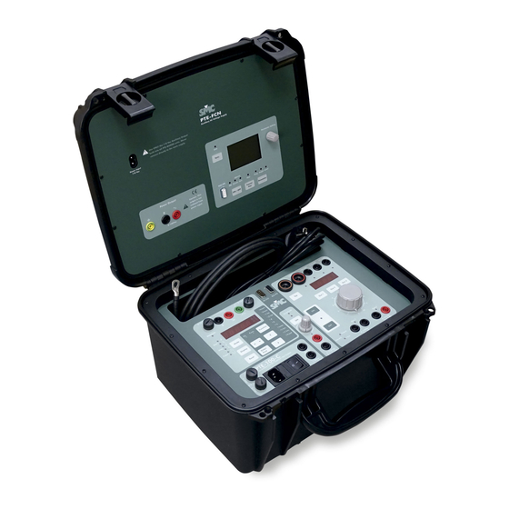
USER’S MANUAL INTRODUCTION The PTE-100-C PRO Relay Test Set is designed to test protective relays based on single-phase current and /or voltage measurement. Its small size, excellent output power and accuracy, quality features, and ease of use, make this product one of the best choices available in its kind. -
Page 9: General Overview
PTE-100-C PRO GENERAL OVERVIEW Technology The PTE-100-C PRO combines state-of-the-art digital technology with the traditional regulation method based on a variable autotransformer and transformer. Analogue and digital electronics convert signals in- and out from the unit in order to be processed and displayed by an 8-bit microprocessor. -
Page 10: Auxiliary Voltage Supply
USER’S MANUAL nected to the ‘zero’ output tap of the power transformer. Measure- ment range switching is automatic. Auxiliary Voltage Supply By means of a transformer with multiple secondary windings, the PTE-100-C PRO features two independent auxiliary voltage outputs: • Out 3 is a variable 0-250 VDC stabilized, electronically protected supply with a dedicated ON/OFF switch, and •... -
Page 11: The Pte-Fcn Variable Voltage Channel
The PTE-FCN variable voltage channel This add-on, installed inside the PTE-100-C PRO’s lid, provides an addi- tional voltage source that is variable in amplitude, frequency and phase angle. The PTE-FCN module is an efficient, accurate and stable amplifier- based voltage source that provides a high quality output. -
Page 12: Description
USER’S MANUAL DESCRIPTION All the elements in the front panel of the PTE-100-C PRO are thoroughly described here. In-depth explanation of their use is given in the Operation section. Many buttons, namely those that perform a different function when held down, effectively actuate when released, rather than when pressed. -
Page 13: Power Output Section
PTE-100-C PRO REPLACE BLOWN FUSES WITH IDENTICAL ONES ONLY. DAMAGE RESULTING FROM INCORRECT FUSE REPLACEMENT IS NOT COVERED BY THE WARRANTY. POWER OUTPUT SECTION This is the right-hand section of the front panel. It contains the main out- put control buttons, the regulation... -
Page 14: Current Output Taps
USER’S MANUAL A harmful amount of current could be injected into the connected load if you accidentally switch the output ON with the variac in a position other than zero. Current output taps At the top of the power output section, four current injection taps are pro- vided to adapt the 100A/10V 50A/20V... -
Page 15: Display #2
PTE-100-C PRO Display #2 All the PTE-100-C PRO output magnitudes are shown on Display #2, lo- cated above the variac’s knob: The units in which the various possible readings are represented are labeled on the right edge ot this LED display:... -
Page 16: Current Tap Selection
Current tap selection. The PTE-100-C PRO cannot detect which of the current taps is connected the load to. Though the current value shown by Dis- play #2 is common to the four taps, some special functions, overload pro- tections and calculations require that the current output tab to which the load is actually connected is identified to the unit. -
Page 17: Auxiliary Voltage
PTE-100-C PRO AUXILIARY VOLTAGE Auxiliary Outputs are intended as general purpose vol- tage supplies, rather than actual power sources. These outputs are also galvanically isolated from each other and from the main power supply. Out 3: 0-250 Out 3 is located on the center section of the front panel. -
Page 18: Timer Section
USER’S MANUAL TIMER SECTION The PTE-100-C PRO’s digital Timer display is located on the left hand sec- tion of the front panel, along with its control buttons and status LEDs. Monitor Inputs Tested relay’s operation is detected by means of two inputs: 1. -
Page 19: Timer Control
The floating decimal point is automatically placed to accommodate the reading to the working measurement range’s accuracy. Timer control The following buttons are used to control the PTE-100-C PRO’s timer opera- tion and various start/stop logics: Successive presses of this button change the start and stop modes Mode of the timer. -
Page 20: Special Functions
USER’S MANUAL Upper LED: the timer will start when injection is switched on. Lower LED: the timer will start when injection is switched off. Upper LED: the timer will stop when the monitor is set to ac- tive. Lower LED: the timer will stop when the monitor is set to inactive. -
Page 21: Measurement Functions
PTE-100-C PRO Once in the functions mode, press this button briefly to go down Function to the next function. You cannot back up. Measurement functions display a steady LED and control functions display a flashing LED. In measurement functions, press and hold this button for 5 seconds to access a secondary measurement mode. -
Page 22: Control Functions
USER’S MANUAL Angle of the impedance Angle between the injected • φ connected to the used cur- current and the voltage rent tap, in 0-360 degree present at the BLACK/RED notation monitor input Apparent power at the used Apparent power at the used •... -
Page 23: Communications
PTE-BUS The PTE-100-C PRO can be used in combination to other EuroSMC’s prod- ucts over this special, high-speed applications bus, in order to extend their capabilities. Thanks to this advanced concept of modularity, the user can... -
Page 24: Operation
USER’S MANUAL OPERATION As a test instrument, you basically use the PTE-100-C PRO to adjust and apply some electrical magnitudes to the tested device and to measure its response time or other test results. Directions to use the features described in the previous section are given here. - Page 25 3. Use the button to identify the used tap to the instrument. The PTE-100-C PRO does not detect the current tap you are using, unless you ‘flag’ it using the TAP button. Some measurement and protective functions will not work if the green LED under the used tap is not lit.
-
Page 26: Overload Protection
USER’S MANUAL If more than one current or voltage tap is connected to a receiver, the readings at Display #2 will be meaningless. Overload protection If injected current exceeds by more than 10% the limit printed above the used tap, the output will be stopped automatically. The ON/OFF LED will then blink and the maximum output current value (or percentage) will be held in Display #2. -
Page 27: Auxiliary Power
Auxiliary electronics are not dimensioned nor calculated for big power values. The PTE-100-C PRO features two auxiliary voltage outputs: one variable 0-250 VDC (Out 3) and one fixed 110 VAC voltage (Out 4). -
Page 28: Out 4 Fixed Ac Auxiliary Supply
The power output will be stopped automatically upon tripping, too, and the applied current or voltage and resulting operation time will be displayed and hold by Display #2 and Display #1 respectively. This is how the PTE-100-C PRO works essentially. - Page 29 Out 2 accordingly until a beep is heard to lock it to Display 4. Connect the relay’s trip contact to the PTE-100-C PRO’s dry (black/green) monitor input. This is for dry contact monitoring. If you are detecting relay operation by means of a contact that is un- der voltage, use the black and red connectors instead.
-
Page 30: The Monitor Input
The PTE-100-C PRO will simulate the presence of a circuit breaker by means of its trip monitor, that will automatically stop both the timer and the power output when the relay operates, thus completing the fault clearance cycle. -
Page 31: Pulse Length Measurement
Remember: monitor activation is signaled by the red LED labeled “Monitor” on the left of Display #1. SPECIAL MEASUREMENT AND CONTROL FUNCTIONS A number of convenience features have been built into the PTE-100-C PRO to make its operation easier, sometimes saving the user from carrying addi- tional instrumentation. -
Page 32: Voltmeter And Frequency Meter
(from Vmon to S) are measurement functions, and the remaining 5 (from % to Preset) are control functions, used to modify the default operation of some PTE-100-C PRO’s features. Voltmeter and Frequency Meter If you need to measure the voltage or the frequency of an external source between 0 to 300 Vac or 400 Vdc, proceed as follows: 1) Enter the Func. -
Page 33: Protecting Your Relay Against Test-Related Accidents
PTE-100-C PRO To read the voltage applied to the load while you are injecting current, do the following: Function 1) Toggle to Func. mode using the button and press Vtap. as necessary to navigate to 2) Connect the load to an appropriate current tap and flag this tap using the button, if not yet done. -
Page 34: Testing Instantaneous Overcurrent
Connect also now the relay’s trip contact to the PTE-100-C PRO’s black/green moni- tor inputs, so that the unit can detect the relay’s operation and stop the test appropriately. Refer to the Timer control section above for details on how to setup the various timer start/stop modes. - Page 35 PTE-100-C PRO was switched on, and it does it at a very high speed. You can now exit from Func. mode. 4) If you wish to avoid injecting an excessive amount of current acci- Ilim dentally while regulating your test current, use the function as described in Protecting Your Relay.
-
Page 36: Pre-Setting A Current Value
USER’S MANUAL Pre-setting a current value If your test object’s load is consistently linear, the Preset function provides a method to set a current value while the output switch is in the OFF position. When Preset is active, the unit calculates the current that would result from each position of the regulation knob at the ‘flagged’... -
Page 37: Calibrating The Pte-100-C Pro
Windows PC, connect it to the unit’s serial port and follow the instructions to enter the readings from reference instruments into your PTE-100-C PRO. Required equipment To calibrate and adjust the readings of your PTE-100-C PRO you need the following equipment: RS-232 communications cable (supplied) ... -
Page 38: General Calibration Procedure
If the serial number of the connected PTE-100-C PRO is new in the FAA-CAL’s equipment database, the program will create a new record for that unit and will acquire and save its adjustments into it automatically. This will allow you to back up to the factory settings in case you make mistakes and render the equipment unusable accidentally. -
Page 39: Specifications
PTE-100-C PRO SPECIFICATIONS A.C. A.C. D.C. AUX D.C. AUX D.C. Output CURRENT VOLTAGE VOLTAGE VOLTAGE VOLTAGE Characteristics «Out 1» «Out 2» «Out 3» «Out 4» AVAILABLE 0-5 A, 0-25 0-250 Vac 0-350 Vdc 0-250 Vdc 110 Vac RANGES A, 0-50 A,... -
Page 40: Meas. Functions
USER’S MANUAL V a.c. V d.c. Frec. V a.c. POT. IMPE TIME ϕ (°) Meas. (Hz) (VA) (sec.) functions (Ω) 20.000 0.0001 00.01 000.01 0.001 250.0 250.0 2000.0 199.9 359.9 99.99 999.99 99999 ±1% R ±1% R ±0.003 ±1% R ±2º... -
Page 41: General Diagram
PTE-100-C PRO GENERAL DIAGRAM... -
Page 42: Front Panel
USER’S MANUAL FRONT PANEL... -
Page 43: The Pte-Fcn Voltage Module
To power the PTE-FCN module, use the included bipolar cord to connect the module exclusively to the 110VAC auxiliary output “Out 4” built into the PTE-100-C PRO. Using any other AC supply can permanently damage the unit and will invalidate the warranty. -
Page 44: Buttons And Leds
USER’S MANUAL BUTTONS AND LEDS The PTE-FCN’s output is regulated by means of a single rotary knob and four control buttons, used as follows: Press this button to switch the output ON and OFF. The associated red LED will indicate the present output state. Press this button to toggle the module’s phase reference from “Line”... -
Page 45: Alarm Indicators
PTE-100-C PRO The rotary knob adjusts the parameter that you have previously selected here. If Synch is set to “Line”, the frequency is fixed so you can only regulate Phase Angle and Level. If Synch is not “Line”, the internal frequency generator is used as reference, so you can only regulate Frequency and Level. -
Page 46: Power-Up State
3 seconds and release it. This display will automatically compen- sate the effect of small temperature variations in the contrast before you need to readjust it again. The PTE-100-C PRO ‘remembers’ the LCD’s con- trast adjustment from one work session to the next. -
Page 47: Pte-Fcn Technical Characteristics
PTE-100-C PRO PTE-FCN TECHNICAL CHARACTERISTICS Power supply 110 Vac ± 10 % Output voltage regulation 0.0 – 140.0 Vac Voltage adjustment resolution / accuracy 0.1 Vac /± 0.1 V Output frequency range 40.0 – 70.0 Hz Frequency adjustment resolution / accuracy 0.1 Hz / ±0.1 Hz... -
Page 48: Pte-Fcn Front Panel
USER’S MANUAL PTE-FCN FRONT PANEL... -
Page 49: After Sales Support
PTE-100-C PRO AFTER SALES SUPPORT WARRANTY This is an expression of trust that our products obtain. based on the reliability and functionality standards that our customers expect. The warranty covers the free replacement or repair of defective components for one year in the terms specified in the supplied warranty statement and registration card. - Page 50 USER’S MANUAL IMPORTANT...
Need help?
Do you have a question about the PTE-100-C PRO and is the answer not in the manual?
Questions and answers