Table of Contents
Advertisement
Quick Links
Quality is the core reference for EuroSMC's activities, aimed to fully satisfy our
customers' needs and expectations.
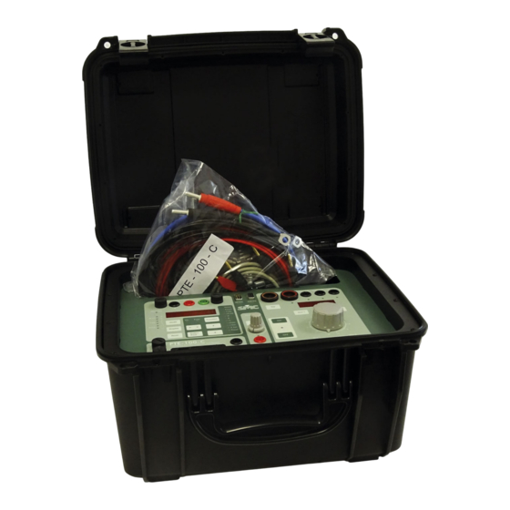
Current and voltage relay testing unit to 250 A
DISCLAIMER
USER'S MANUAL
The information, product specifications, and technical data contained in this
document imply no contractual binding to EuroSMC's responsibility. The user is
the sole responsible for the application of the products mentioned in this
document. EuroSMC explicitly exonerates itself from liability to accidents or
unwanted results, directly or indirectly derived from mistakes made in the
writing of this document. Copying or reproducing all or part of this document is
not allowed without the explicit written permission from EuroSMC. Due to
continuing development and quality improvements, EuroSMC reserves the right
to make changes in their products without notice.
PTE-100-C
REFERENCE: FAAVMV02
EDITION: May 17
th
, 2013
VERSION: 10
Advertisement
Table of Contents

Related Manuals for SMC Networks PTE-100-C


Summary of Contents for SMC Networks PTE-100-C
- Page 1 Copying or reproducing all or part of this document is not allowed without the explicit written permission from EuroSMC. Due to continuing development and quality improvements, EuroSMC reserves the right to make changes in their products without notice. PTE-100-C REFERENCE: FAAVMV02 EDITION: May 17 , 2013...
-
Page 2: Table Of Contents
OPERATION ............. 22 INDEX CURRENT AND VOLTAGE INJECTION ....... 22 AC Current Injection ..............22 PTE-100-C PACKING LIST .......... 5 Overload protection ..............24 Voltage Injection ................ 24 INTRODUCTION ............6 AUXILIARY POWER ............25 GENERAL OVERVIEW ..........7 Out 3 variable DC auxiliary supply ..........25 Technology ................. -
Page 3: Pte-100-C Packing List
PTE-100-C USER’S MANUAL PTE-100-C PACKING LIST INTRODUCTION The PTE-100-C Relay Test Set is designed to test protective relays based on single-phase current and /or voltage measurement. PTE-100-C unit Its small size, excellent output power and accuracy, quality features, and Nylon bag ease of use, make this product one of the best choices available in its kind. -
Page 4: General Overview
Auxiliary Voltage Supply Technology By means of a transformer with multiple secondary windings, the PTE-100-C The PTE-100-C combines state-of-the-art digital technology with the tradi- features two independent auxiliary voltage outputs: tional regulation method based on a variable autotransformer and trans- former. -
Page 5: Description
PTE-100-C USER’S MANUAL DESCRIPTION All the elements in the front panel of the PTE-100-C are thoroughly de- scribed here. In-depth explanation of their use is given in the Operation section. Many buttons, namely those that perform a different function when held down, effectively actuate when released, rather than when pressed. -
Page 6: Output On/Off Buttons
PTE-100-C USER’S MANUAL REPLACE BLOWN FUSES WITH IDENTICAL ONES ONLY. DAMAGE A harmful amount of current could be injected into the connected RESULTING FROM INCORRECT FUSE REPLACEMENT IS NOT COVERED load if you accidentally switch the output ON with the variac in a BY THE WARRANTY. -
Page 7: Display #2
0-250 VDC). Out 3, located in the center section of the PTE-100-C panel, is switched on, regulated and protected All the PTE-100-C output magnitudes are shown on Display #2, located independently from the other outputs. above the variac’s knob: A green LED above its tap will identify the displayed output. -
Page 8: Auxiliary Voltage
TIMER SECTION Auxiliary Outputs are intended as general purpose volt- The PTE-100-C’s digital Timer display is located on the left hand section of age supplies, rather than actual power sources. These the front panel, along with its control buttons and status LEDs. -
Page 9: Timer Control
You can adapt yourself to different timing conditions by setting up the vari- mode. When in the special functions mode, Display#1 will tem- ous combinations of start and stop events for the PTE-100-C’s timer. The porarily show measurement and setup values default combination –first and third LEDs- sets the timer to start when the... -
Page 10: Measurement Functions
PTE-100-C USER’S MANUAL Once in the functions mode, press this button briefly to go down Angle of the impedance Angle between the injected φ Function to the next function. You cannot back up. Measurement functions connected to the used cur- current and the voltage display a steady LED and control functions display a flashing LED. -
Page 11: Communications
OPERATION The PTE-100-C features two different means of communicating with other As a test instrument, you basically use the PTE-100-C to adjust and apply equipment: standard RS-232 and EuroSMC’s proprietary PTE-BUS commu- some electrical magnitudes to the tested device and to measure its response nications. -
Page 12: Overload Protection
Display #2. With the 100A/10V Current Tap, however, this protec- tion is timed inversely to the amount of excess, according to the table below. The PTE-100-C does not detect the current tap you are using, unless Maximum current allowed through this tap is roughly 250 Amps. -
Page 13: Auxiliary Power
Out 3 1. Press and hold until you hear a beep. The green #2 and Display #1 respectively. This is how the PTE-100-C works essential- LED under its small regulation knob will lit. This will bind Display #2 to this output. -
Page 14: The Monitor
‘flag’ LED on clearing the fault. The PTE-100-C will simulate the presence of a circuit breaker by means of its trip monitor, that will automatically stop both the... -
Page 15: Special Measurement And Control Functions
(and further deacti- vate) their secondary measurement mode. A number of convenience features have been built into the PTE-100-C to make its operation easier, sometimes saving the user from carrying addi- Output Current-related Measurements tional instrumentation. -
Page 16: Protecting Your Relay Against Test-Related Accidents
Connect also now nected load. the relay’s trip contact to the PTE-100-C’s black/green monitor in- puts, so that the unit can detect the relay’s operation and stop the Impedance measurement requires a minimum amount of current (at least 10 test appropriately. -
Page 17: Pre-Setting A Current Value
PTE-100-C USER’S MANUAL the output was switched on, and it does it at a very high speed. You Pre-setting a current value can now exit from Func. mode. If your test object’s load is consistently linear, the Preset function provides a 4) If you wish to avoid injecting an excessive amount of current acci- method to set a current value while the output switch is in the OFF position. -
Page 18: Calibrating The Pte-100-C
Refer to Special Functions at the DESCRIPTION section for details on the use of the Preset and |Z|tap If the serial number of the connected PTE-100-C is new in the FAA-CAL’s functions. -
Page 19: Specifications
PTE-100-C USER’S MANUAL SPECIFICATIONS Meas. V a.c. V d.c. Frec. V a.c. () POT. IMPED. TIME (Hz) (VA) (Ω) (sec. functions 20.000 0.0001 00.01 000.01 00.00 Output A.C. A.C. D.C. AUX D.C. AUX D.C. CURRENT VOLTAGE VOLTAGE VOLTAGE VOLTAGE... -
Page 20: After Sales Support
PTE-100-C USER’S MANUAL AFTER SALES SUPPORT GENERAL DIAGRAM WARRANTY This is an expression of trust that our products obtain. based on the reliability and functionality standards that our customers expect. The warranty covers the free replacement or repair of defective components for one year in the terms specified in the supplied warranty statement and registration card. -
Page 21: Front Panel
PTE-100-C FRONT PANEL...
Need help?
Do you have a question about the PTE-100-C and is the answer not in the manual?
Questions and answers