Table of Contents
Advertisement
Quick Links
Advertisement
Table of Contents

Subscribe to Our Youtube Channel
Related Manuals for Icom GM600


Summary of Contents for Icom GM600
- Page 1 BASIC MANUAL VHF MARINE TRANSCEIVER GM600...
-
Page 2: Important
NOTE You must connect the GM600 to the DC power supply of personal injury, fire or electric shock. through the PS-310 that is sold by the set with the GM600. EN60945 Environmental category The GM600 is protected from the weather. -
Page 3: In Case Of Emergency
It is recommended that antenna of a maximum gain of 3 dB is used. If higher gain antenna are required then USING DIGITAL SELECTIVE CALLING (Ch 70) please contact your Icom distributor for revised installation DISTRESS CALL PROCEDURE recommendations. 1. While lifting up the key cover, hold down [DISTRESS]... -
Page 4: Precautions
KEEP the transceiver and microphone at least 1 m away from the vessel’s magnetic navigation compass. Icom is not responsible for the destruction or damage to the Icom DO NOT place or leave the transceiver in areas with temperatures transceiver, if the malfunction is because of: below –15°C or above +55°C, or in areas subject to direct sunlight,... -
Page 5: Table Of Contents
■ DSC Task mode ..............8 ■ Sending a Distress call ............10 ■ Sending an Individual call ............. 11 5 MENU SCREEN ..............13–14 The following items are sold by the set with the GM600. ■ Construction ................13 PS-310 Screws (5×20 mm) Flat washers (M5) ■... -
Page 6: Operating Rules
OPERATING RULES D Priorities (2) OPERATOR’S LICENSE • Read all rules and regulations pertaining to call priorities, A Restricted Radiotelephone Operator Permit is the license and keep an up-to-date copy handy. Safety and distress most often held by small vessel radio operators when a calls take priority over all others. -
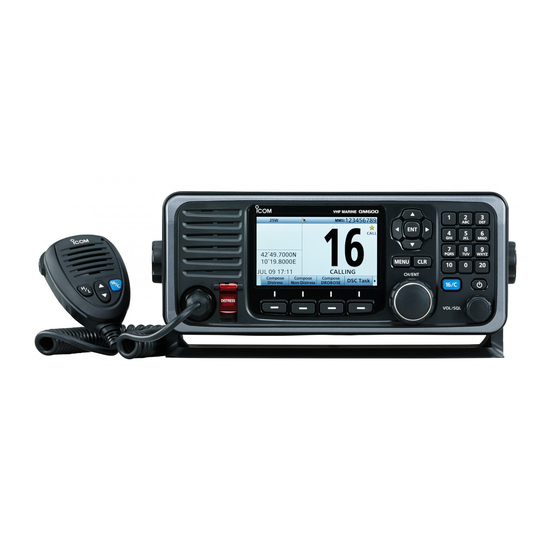
Page 7: Panel Description
PANEL DESCRIPTION ■ Front panel Distress key [DISTRESS] Enter key [ENT] Left and Right keys [Ω]/[≈] Function display Up and Down keys [∫]/[√] Speaker (See the next page) Keypad Power key [ ] Channel 16/Call channel key [16/C] Mic connector Software keys Volume/Squelch dial [VOL/SQL] Clear key [CLR]... -
Page 8: Function Display (Main Screen)
PANEL DESCRIPTION ■ Function display (Main screen) q Status area D Status area w Task area e Information area r Channel area The current status is displayed in the Status area. Indication Description SCAN 16 Displayed during a Priority scan. SCAN Displayed during a Normal scan. - Page 9 PANEL DESCRIPTION D Information area D Channel area The 9 digit MMSI (Maritime Mobile Service Identity: DSC The selected operating channel number, channel name, and self ID) code and the following indications are displayed in the following indications are displayed in the Channel area. the Information area.
-
Page 10: Software Key Function
PANEL DESCRIPTION ■ Software key function ■ Speaker Microphone The transceiver has the software keys for various functions. PTT switch The key function is displayed above the software key, as Microphone shown below. [PTT] D Selecting the software key function Up and Down When “Ω”... -
Page 11: Preparation
PREPARATION ■ Entering the MMSI code First, you must enter the 9 digit MMSI e Enter your 9 digit MMSI code. y After entering the 9th digit, register (Maritime Mobile Service Identity: DSC the ID. Push self ID) code at power ON. Push You can perform this initial code entry ONLY ONCE. -
Page 12: Basic Operation
BASIC OPERATION ■ Transmitting and receiving Follow the procedures as described below to transmit and IMPORTANT: To maximize the readability of your receive. transmitted signal at a receiver station, pause a second after pushing [PTT], and then hold the microphone 5 to 10 q Turn ON the transceiver cm from your mouth and speak at your normal voice level. -
Page 13: Dsc Task Mode
BASIC OPERATION ■ DSC Task mode D About “Active” and “Hold” After sending or receiving a DSC call, NOTE: The Task window has a TOT the transceiver enters the DSC Task The Task mode has two statuses, Active (Time-out Timer) function. When you mode. - Page 14 BASIC OPERATION ■ DSC Task window (Continued) D Software key functions When entering the Task mode, the The following functions may be The following functions are displayed, following functions are displayed first. displayed, depending on the call type. after receiving an Individual call. FUNCTION DESCRIPTION FUNCTION...
-
Page 15: Sending A Distress Call
BASIC OPERATION ■ Sending a Distress call e After sending, the following screen is NEVER MAKE A DISTRESS CALL IF NOTE: displayed. A distress alert default contains: YOUR SHIP OR A PERSON IS NOT - Nature of distress: IN AN EMERGENCY. Undesignated distress (Simple call) A DISTRESS CALL SHOULD BE - Position information:... -
Page 16: Sending An Individual Call
BASIC OPERATION ■ Sending an Individual call The Individual call function enables t Select a desired option. e Select a desired individual address, or “Manual Input.” you to transmit a DSC signal to Rotate Rotate only a specific coast station or ship. -
Page 17: Basic Operation
BASIC OPERATION i Send an Individual call. !0 When receiving the acknowledgement: • Alarm sounds. • The following window is displayed. (Example: Able to comply) Push o After sending, the following screen is displayed. !1 Push any [Alarm Off] !2 Push any [Close Call RCVD Window] When you receive “ACK (Unable)”... -
Page 18: Menu Screen
MENU SCREEN You can use the Menu screen to set infrequently changed values or function settings. ■ Construction The Menu screen is constructed in a Compose Distress DSC Log Radio Settings Nature of Distress Received Call Log Scan Type tree structure. •... -
Page 19: Selecting A Menu Item
MENU SCREEN ■ Selecting a Menu item Follow the procedures as described r Select “Tri-Watch.” For your information: below to select a Menu item. You can use the following key Rotate functions in the MENU screen. Example: Set the Tri-watch function. FUNCTION ACTION q Push [MENU]. -
Page 20: Connections
CONNECTIONS ■ Connections Remote alarm output terminal • 4 V DC* • Maximum 10 mA* * When the external equipment is connected between this terminal and the GND terminal. When DSC call that is related to “Distress” as described below is received, 4 V DC is output and the key backlight blinks. - Page 21 CONNECTIONS w DC POWER CONNECTOR r D-SUB 25-PIN Connects the PS-310 with the DC power cable of the PS- Connects to a printer (IBM ® centronics or compatible) to 310. print out the received DSC call contents. t ANTENNA CONNECTOR (to receive on Channel 70) CAUTION: After connecting the DC power cable, cover the y ANTENNA CONNECTOR connector with a tape, as shown below, to prevent water...
-
Page 22: Power Supply Connections
CONNECTIONS ■ Power supply connections D Connecting to the DC power supply through the PS-310 You must connect the GM600 to the DC power source through the PS-310 , sold by the set dc power supply Screw Spring washer with the GM600, when you operate the GM600. -
Page 23: Specifications And Options
SPECIFICATIONS AND OPTIONS ■ Specifications D Receiver These specifications are described when the GM600 is used with the PS-310. • Receive system: Double conversion superheterodyne All stated specifications are subject to change without notice or • Sensitivity: obligation. –7 dBµ emf (typical) (20 dB SINAD) DSC (CH70): –7 dBµ... -
Page 24: Country Code List
COUNTRY CODE LIST ISO 3166-1 Country Codes Country Codes Austria Liechtenstein Belgium Lithuania Bulgaria Luxembourg Croatia Malta Czech Republic Netherlands Cyprus Norway Denmark Poland Estonia Portugal Finland Romania France Slovakia Germany Slovenia Greece Spain Hungary Sweden Iceland Switzerland Ireland Turkey Italy United Kingdom Latvia... - Page 25 MEMO...
- Page 26 < Intended Country of Use > A-7240-2EU-w Printed in Japan 2015–2016 Icom Inc. © 1-1-32 Kamiminami, Hirano-ku, Osaka 547-0003, Japan Printed on recycled paper with soy ink.
Need help?
Do you have a question about the GM600 and is the answer not in the manual?
Questions and answers