
Related Manuals for Icom IC-M1


Summary of Contents for Icom IC-M1
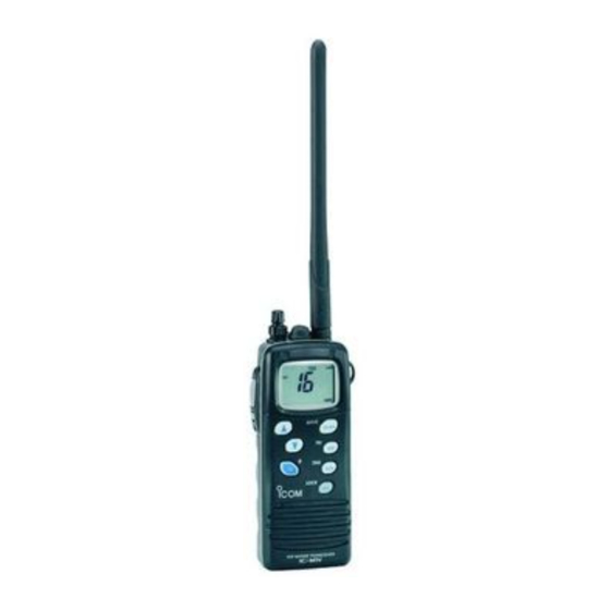
- Page 1 INSTRUCTION MANUAL VHF MARINE TRANSCEIVER iC- m1 This device complies with Part 15 of the FCC Rules. Operation is subject to the condition that this device does not cause harmful interference.
-
Page 2: Cautions
SAVE THIS INSTRUCTION MANUAL — carefully and completely struction manual contains important operating instructions for the IC-M1. KEEP hold the transceiver so that ship’s navigation compass. DO NOT atures below –4°F (–20°C) or above +140°F (+60°C) or, in... -
Page 3: Table Of Contents
TABLE OF CONTENTS IMPORTANT ... i CAUTIONS ... i TABLE OF CONTENTS ... ii 1 PANEL DESCRIPTION ... 1–3 Front panel ... 1 Top and side panels ... 2 Function display ... 3 2 BASIC OPERATION ... 4–9 Operating rules ... 4 Channel selection ... -
Page 4: Panel Description
PANEL DESCRIPTION Front panel FUNCTION DISPLAY (p. 3) CHANNEL 16 SWITCH [16 •9 • Selects channel 16 when pushed. (p. 5) • Selects the call channel when pushed for 1 sec. (p. 5) • Enters call channel write mode when the call channel is selected and this switch is pushed for 3 sec. -
Page 5: Top And Side Panels
Top and side panels SQUELCH/MONITOR SWITCH [SQL] • Opens the squelch and monitors the op- erating channel while being pushed. • Sets the squelch level with the channel selector. (p. 6) PTT SWITCH [PTT] Push and hold to transmit; release to re- ceive. -
Page 6: Function Display
PANEL DESCRIPTION Function display LOW POWER INDICATOR (p. 7) • Appears when low power is selected. • Blinks when extra low power is selected. CALL CHANNEL INDICATOR (p. 5) Appears when a call channel is selected. BUSY INDICATOR (p. 7) Appears when receiving a signal or when the squelch opens. -
Page 7: Basic Operation
Operating rules • PRIORITIES 1 Read all rules and regulations pertaining to priorities and keep an up-to-date copy handy. Safety and distress calls take priority over all others. 2 You must monitor channel 16 when you are not operating on another channel. 3 False or fraudulent distress signals are prohibited and pun- ishable by law. -
Page 8: Channel Selection
BASIC OPERATION Channel selection D Channel 16 Channel 16 is the distress channel. It is used for establishing initial contact with another station and for emergency com- munications. Channel 16 is monitored during dualwatch/ tri-watch. While standing by you are required to monitor chan- nel 16. -
Page 9: Lock Function
NOAA (National Oceanographic and Atmospheric Administration) broadcasts. The IC-M1 can detect a weather alert tone on the selected weather channel while receiving the channel, during standby on a regular channel or while scanning. See the “SET mode items”... -
Page 10: Receiving And Transmitting
BASIC OPERATION Receiving and transmitting CAUTION: Transmitting without an antenna may dam- age the transceiver. 1 Rotate [OFF/VOL] clockwise to turn power ON, then set to the 10 o’clock position. - Use the squelch function to mute any audio noise if necessary. Refer to the previous page for details. -
Page 11: Optional Voice Scrambler Operation
Optional voice scrambler operation D Activating the scrambler The optional voice scrambler provides private communica- tions. In order to receive or send scrambled transmissions you must first activate the scrambler function. To activate the func- tion, an optional UT-98 is necessary. Ask your dealer for de- tails. -
Page 12: Call Channel Programming
BASIC OPERATION Call channel programming The call channel key is used to select channel 9, however, you can program your most often-used channels in each channel group for quick recall. 1 Push [ U/I/C] for 1 sec. CH/WX• several times to select the de- sired channel group (USA, INT, CAN) to be programmed. -
Page 13: Dualwatch/Tri-Watch
Description Dualwatch monitors channel 16 while you are receiving an- other channel; tri-watch monitors channel 16 and the call channel while receiving another channel. DUALWATCH/TRI-WATCH SIMULATION Dualwatch Tri-watch • If a signal is received on channel 16, dualwatch/tri-watch pauses on channel 16 until the signal disappears. •... -
Page 14: Scan Operation
SCAN OPERATION Scan types Scanning is an efficient way to locate signals quickly over a wide frequency range. The transceiver has priority scan and normal scan. In addition, weather alert and automatic scan start function is available for standby convenience. (p. 14) PRIORITY SCAN CH 01 CH 16... -
Page 15: Setting Tag Channels
Setting tag channels For more efficient scanning, add desired channels as tag channels or clear tag channels for unwanted channels. Channels set as non-tag channels will be skipped during scanning. Tag channels can be assigned to each channel group (USA, CAN, INT) independently. 1 Select the desired channel group (USA, CAN, INT) by pushing [ U/I/C] for 1 sec., if desired. -
Page 16: Set Mode
SET MODE SET mode programming SET mode is used to change the conditions of 6 transceiver functions: the beep tone function, the automatic backlighting, weather alert function, normal/priority scan, scan resume timer and auto scan function. 1 Turn power OFF. 2 While pushing [SQL], turn power ON and continue push- ing [SQL] until “bP”... - Page 17 D Weather alert function “AL” An NOAA broadcast station transmits an weather alert tone before an important weather information. When the weather alert function is turned ON, the transceiver detects the alert, then flashes the “ALT” indicator until the transceiver is oper- ated.
-
Page 18: Battery Charging
BATTERY CHARGING Battery cautions NEVER incinerate used battery packs. Internal battery gas may cause an explosion. NEVER immerse the battery pack in water. If the battery pack becomes wet, be sure to wipe it dry BEFORE attaching it to the transceiver. NEVER short terminals of the battery pack. - Page 19 D Attaching the AD-58 to a wall Eyelet: a rubber band to secure the transceiver, if desired. D Installing the AD-69 to the BC-119 1 Connect the cable as shown below. 2 Attach the AD-69 with the 2 supplied screws. AD-69 BC-119 D Charging with the AD-58...
-
Page 20: Unpacking And Accessory Attachment
UNPACKING AND ACCESSORY ATTACHMENT D Unpacking The following accessories are supplied: 1 Flexible antenna (FA-S57V) ... 1 2 Handstrap ... 1 3 Belt clip ... 1 4 Screws for the belt clip (M3 5 Battery charger (AD-58) ... 1 6 Screws for the AD-58 (M3.5 7 AC adapter (BC-122A/E) ... -
Page 21: Troubleshooting
PROBLEM POSSIBLE CAUSE No power comes ON. • The battery is exhausted. • Bad connection to the battery pack. No sound comes from • Squelch level is too deep. the speaker. • Volume level is too low. • Speaker has been exposed to water. Transmitting is impossi- •... -
Page 22: Channel List
CHANNEL LIST Channel number Frequency (MHz) CAN Transmit Receive 156.050 160.650 156.050 156.050 156.100 160.700 156.100 156.100 156.150 160.750 156.150 156.150 156.200 160.800 04A 156.200 156.200 156.250 160.850 05A 156.250 156.250 156.300 156.300 156.350 160.950 07A 156.350 156.350 156.400 156.400 156.450 156.450 156.500 156.500 156.550 156.550... -
Page 23: Specifications And Options
Current drain (at 8.4 V) : TX High Max. audio Power saved13 mA typ. Power supply requirement : Icom battery packs Frequency stability : ±10 ppm (–20°C to +60°C) Useable temperature range : –20°C to +60°C; –4°F to +140°F Dimensions (with BP-185) : 52.5 (W) 129 (H) 30 (D) mm... - Page 24 A-5373H-1US-q Printed in Japan 6-9-16 Kamihigashi, Hirano-ku, Osaka 547 Japan Copyright © 1995 by Icom Inc.
Need help?
Do you have a question about the IC-M1 and is the answer not in the manual?
Questions and answers
Hi , I need a new batteri pack for my ICOM (IC-M1), serial no: 03540, how do I get hold of one? Please advice,
You can obtain a new battery pack for the Icom IC-M1 by purchasing the ICOM IC-M1 Two Way Radio Battery (Product Number: ICBP186) online. It is available in stock for USD $49.81 (with a 25% discount). The replacement battery codes are ICOM BP-186 and ICOM BP-186H. Visit the relevant online retailer or contact them for purchase.
This answer is automatically generated