Table of Contents
Advertisement
Quick Links
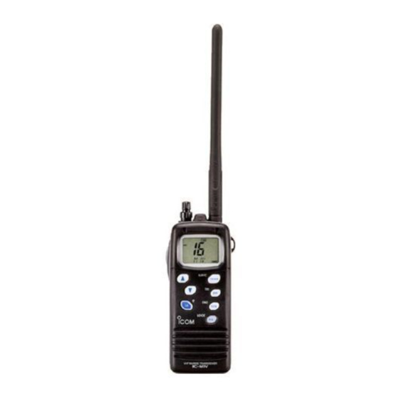
INSTRUCTION MANUAL
VHF MARINE TRANSCEIVER
iM1V
This device complies with Part 15 of the FCC rules. Operation is sub-
ject to the following two conditions: (1) This device may not cause
harmful interference, and (2) this device must accept any interference
received, including interference that may cause undesired operation.
Advertisement
Table of Contents

Related Manuals for Icom IC-M1V


Summary of Contents for Icom IC-M1V
- Page 1 INSTRUCTION MANUAL VHF MARINE TRANSCEIVER iM1V This device complies with Part 15 of the FCC rules. Operation is sub- ject to the following two conditions: (1) This device may not cause harmful interference, and (2) this device must accept any interference received, including interference that may cause undesired operation.
-
Page 2: Foreword
FOREWORD Thank you for purchasing this Icom product. The IC-M1V is designed and built with Icom’s superi- MARINE TRANSCEIVER or technology and craftsmanship. With proper care, this prod- uct should provide you with years of trouble-free operation. IMPORTANT READ ALL INSTRUCTIONS before using the transceiver. -
Page 3: In Case Of Emergency
For U.S.A. only CAUTION: Changes or modifications to this device, not ex- pressly approved by Icom Inc., could void your authority to operate this device under FCC regulations. IN CASE OF EMERGENCY If your vessel requires assistance, contact other vessels and the Coast Guard by sending a distress call on channel 16;... -
Page 4: Table Of Contents
TABLE OF CONTENTS FOREWORD ... i IMPORTANT ... i EXPLICIT DEFINITIONS ... i CAUTION ... i IN CASE OF EMERGENCY ... ii TABLE OF CONTENTS ... iii 1 OPERATING RULES... 1 2 PANEL DESCRIPTION ... 2–5 Front panel ... 2 Function display ... -
Page 5: Operating Rules
× PRIORITIES q Read all rules and regulations pertaining to priorities, and keep an up-to-date copy handy. Safety and distress calls take priority over all others. w You must monitor channel 16 when you are not operating on another channel. e False or fraudulent distress signals are prohibited and pun- ishable by law. -
Page 6: Panel Description
PANEL DESCRIPTION Panel description Function display (p. 4) q VOLUME CONTROL [VOL] Turns power ON and adjusts the audio level. (p. 9) w SQUELCH CONTROL [SQL] Sets the squelch threshold level. (p. 9) e PTT SWITCH [PTT] Transmits during push; receives during release. (p. 9) r MONITOR SWITCH [MONI] Opens the squelch and monitors the operating channel while being pushed. - Page 7 y CHANNEL UP/DOWN SWITCHES [Y Y ]/[Z Z ] Push either switch to change the operating channel. (pgs. 7–9) Checks tag channels or changes scanning direction dur- ing scan. (p. 13) Push either switch to change the setting during set mode.
-
Page 8: Function Display
PANEL DESCRIPTION Function display TX BUSY ATIS q BUSY INDICATOR (p. 9) Appears while receiving a signal or while the squelch is open. w TRANSMIT INDICATOR (p. 9) Appears while transmitting. e CHANNEL GROUP INDICATORS (p. 8) Appears “USA” when U.S.A.; “INT” when International; “CAN”... - Page 9 u BATTERY INDICATOR Indicates remaining battery power. Indication Battery level Full Middle i LOCK INDICATOR (p. 10) Appears while the lock function is activated. o SUB CHANNEL READOUT • Indicates channel 16 during priority scan. (p. 13) • Indicates channel 16 during dualwatch or tri-watch. (p.
-
Page 10: Supplied Accessories And Attachments
SUPPLIED ACCESSORIES AND ATTACHMENTS × Supplied accessories The following accessories are supplied: q Flexible antenna (FA-S57V) ...1 w Battery pack (BP-215) ...1 e Battery charger (AD-95) ...1 r AC adapter* (BC-122A/E/V*) ...1 t Handstrap ...1 y Belt clip ...1 u Screws for the belt clip (M3 i Screws for the AD-95 (M3.5 *Depending on version ×... -
Page 11: Basic Operation
Channel selection × Channel 16 Channel 16 is the distress channel. It is used for establishing initial contact with another station and for emergency com- munications. Channel 16 is automatically monitored during both dualwatch and tri-watch. While standing by, you must monitor channel 16. -
Page 12: Weather Channels
NOAA (National Oceanographic and Atmospheric Administration) broadcasts. The IC-M1V can detect a weather alert tone on the selected weather channel while receiving in another channels, during standby on a regular channel, or while scanning. See the “SET mode items”... -
Page 13: Receiving And Transmitting
Receiving and transmitting CAUTION: Transmitting without an antenna may dam- age the transceiver. q Rotate [VOL] clockwise to turn power ON, then set to the 10 o’clock position. • Turn [SQL] clockwise to mute any audio noise if necessary. CAUTION: If the comment, “WET INSIDE”, appears, turn the power OFF immediately, and contact your local dealer, or ser- vice center. -
Page 14: Lock Function
BASIC OPERATION Lock function This function electronically locks all keys and switches to pre- vent accidental frequency changes and function access. Push [H/L•LOCK] for 2 sec. to turn the lock function ON and OFF. • Only [PTT], [H/L] and [MONI] are functional. Automatic backlighting This function is convenient for nighttime operation. -
Page 15: Call Channel Programming
Call channel programming The call channel key is used to select channel 9, however, you can program your most often-used channels in each channel group for quick recall. q Push [CH/WX•U/I/C] for 2 sec. sev- eral times to select the desired channel group (USA, INT, CAN) to be programmed. -
Page 16: Scan Operations
SCAN OPERATIONS Scan types Scanning is an efficient way to locate signals quickly over a wide frequency range. The transceiver has priority scan and normal scan. In addition, weather alert and an automatic scan start func- tion is available for standby convenience. (pgs. 17, 18) PRIORITY SCAN CH 01 CH 16... -
Page 17: Setting Tag Channels
Setting tag channels For more efficient scanning, add desired channels as tag channels or clear tag channels for unwanted channels. Channels, set as non-tag channels will be skipped during scanning. Tag channels can be assigned to each channel group independently. (USA, INT, CAN) q Select the desired channel group (USA, INT, CAN) -
Page 18: Dualwatch/Tri-Watch
DUAL WATCH/TRI-WATCH Description Dualwatch monitors channel 16 while you are receiving an- other channel; tri-watch monitors channel 16 and the call channel while receiving another channel. DUALWATCH/TRI-WATCH SIMULATION Dualwatch • If a signal is received on channel 16, dualwatch/tri-watch pauses on channel 16 until the signal disappears. -
Page 19: Channel Comment Programming
CHANNEL COMMENT PROGRAMMING About the channel comment The IC-M1V has a capability to assign up to 10-character channel comments for each operating channel, including the weather channel. This provides easy recognition of channel usage, or station names, etc. When shipped from the factory, the IC-M1V is programmed with default comments for each VHF marine channel. -
Page 20: Set Mode
SET MODE SET mode programming SET mode is used to change the condi- tion of 10 of the transceiver’s functions: beep tone function, weather alert func- tion, scan type (normal/priority) sume timer, auto scan function, auto- matic backlighting, power save function, self check function, voice scrambler type and scrambling code. - Page 21 × Weather alert function “WX ALERT” An NOAA broadcast station transmits a weather alert tone before any important weather information. When the weather alert function is turned ON, the trans- ceiver detects the alert, then flashes the “ALT” indicator until the transceiver is op- erated.
-
Page 22: Auto Scan Function
SET MODE × Auto scan function “AUTO SCAN” While in standby, this function automat- ically starts the desired scan (normal or priority scan) 30 sec. after operation. • The comment indicator indicates “SCAN” while scanning. The transceiver has a power save function, but it does not activate when the auto scan function is in use. - Page 23 × Self check function “SELF CHECK” The self check function checks trans- ceiver conditions by itself, and informs you in case a problem is found. The fol- lowing items are checked after the power is turned ON, then, switches to operation mode.
-
Page 24: Battery Charging
BATTERY CHARGING Caution NEVER incinerate used battery packs. Internal battery gas may cause an explosion. NEVER immerse the battery pack in water. If the battery pack becomes wet, be sure to wipe it dry immediately (particularly the battery terminals) BEFORE attaching it to the transceiver. Otherwise, the terminals will become corroded, or cause con- nection failure, etc. - Page 25 × AD-95 installations • To a desktop • To a wall Supplied screws • For convenience: Eyelet: USE a rubber band to secure the transceiver, if desired. × Charging q Connect the AC adapter (BC-122A/E/V) or optional cable (CP-17L or OPC-515L) as shown below. w Insert the battery pack with/without the transceiver into the Supplied screws charger.
-
Page 26: Speaker-Microphone
SPEAKER-MICROPHONE Descriptions Alligator type clip To attach the speaker-mic. to your shirt or collar, etc. PTT switch Transmits during push Receives during release Microphone Speaker NEVER immerse the connector in water. If the connector be- comes wet, be sure to dry BEFORE attaching it to the trans- ceiver. -
Page 27: Troubleshooting
PROBLEM POSSIBLE CAUSE No power comes ON. • The battery is exhausted. • Bad connection of the battery pack. No sound comes from • Squelch level is too deep. the speaker • [VOL] level is too low. Transmitting is impossi- •... -
Page 28: Channel List
CHANNEL LIST Channel Number Frequency (MHz) USA INT CAN Transmit Receive 156.050 160.650 156.050 156.050 156.100 160.700 156.150 160.750 156.150 156.150 156.200 160.800 04A 156.200 156.200 156.250 160.850 05A 156.250 156.250 156.300 156.300 156.350 160.950 07A 156.350 156.350 156.400 156.400 156.450 156.450 156.500 156.500 156.550 156.550... -
Page 29: Quick Reference
QUICK REFERENCE Important operating instructions are summed up in this and the following page for your simple reference. By cutting along the line and folding on the dotted line, it will become a card sized operating guide which can easily be carried in a card case or wallet, etc. -
Page 30: Recommendation
RECOMMENDATION CLEAN THE TRANSCEIVER THOR- OUGHLY WITH FRESH WATER after exposure to salt water. Otherwise, the transceiver’s keys, switch- es and controllers may become inopera- ble due to salt crystallization. -
Page 31: Specifications And Options
• Current drain (at 7.4 V) : TX at 5 W Max.audio Power saved • Power supply requirement : Icom battery pack; BP-215 • Frequency stability : ±10 ppm (–20°C to +60°C; –4°F to +140°F) • Dimensions : 52.5(W) 129(H) 30(D) mm (with BP-215) ⁄... - Page 32 Count on us! A-5626H-1EX-e Printed in Japan 1-1-32 Kamiminami, Hirano-ku, Osaka 547-0003 Japan © 1999–2001 Icom Inc.
Need help?
Do you have a question about the IC-M1V and is the answer not in the manual?
Questions and answers