Table of Contents
Advertisement
Quick Links
Advertisement
Chapters
Table of Contents
Troubleshooting

Subscribe to Our Youtube Channel
Related Manuals for Icom GM600


Summary of Contents for Icom GM600
- Page 1 INSTRUCTION MANUAL VHF MARINE TRANSCEIVER GM600...
-
Page 2: Important
Thank you for choosing this Icom product. EXPLICIT DEFINITIONS This product is designed and built with Icom’ s state of the art technology and craftsmanship. WORD DEFINITION With proper care, this product should provide you with years of trouble-free operation. -
Page 3: In Case Of Emergency
It is recommended that antenna of a maximum gain of 3 dB is used. If higher gain antenna are required then USING DIGITAL SELECTIVE CALLING (Ch 70) please contact your Icom distributor for revised installation DISTRESS CALL PROCEDURE recommendations. 1. While lifting up the key cover, hold down [DISTRESS]... -
Page 4: Precautions
PRECAUTIONS RWARNING! NEVER connect the transceiver to an AC outlet. DO NOT use harsh solvents such as Benzine or alcohol to This may pose a fire hazard or result in an electric shock. clean the transceiver, as they will damage the transceiver’s surfaces. -
Page 5: Country Code List
COUNTRY CODE LIST ACTION ICON DESCRIPTION • ISO 3166-1 The following describes the [CH/ENT], [ENT] and the keypad operations in this instruction manual. Country Codes Country Codes Austria Liechtenstein Rotate Belgium Lithuania : Rotate [CH/ENT] to select. Bulgaria Luxembourg Push Croatia Malta : Push [ENT] to enter or set. -
Page 6: Table Of Contents
TABLE OF CONTENTS IMPORTANT ..................i 7 DSC OPERATION ...............23–75 EXPLICIT DEFINITIONS ..............i ■ DSC address ID ..............23 DISPOSAL ..................i ■ Entering the position and time ..........25 ■ DSC Task mode ..............27 IN CASE OF EMERGENCY ............. ii INSTALLATION NOTE .............. -
Page 7: Operating Rules
OPERATING RULES D Priorities (2) OPERATOR’S LICENSE • Read all rules and regulations pertaining to call priorities, A Restricted Radiotelephone Operator Permit is the license and keep an up-to-date copy handy. Safety and distress most often held by small vessel radio operators when a calls take priority over all others. -
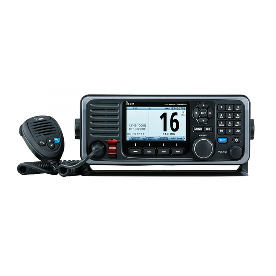
Page 8: Panel Description
PANEL DESCRIPTION ■ Front panel q DISTRESS KEY [DISTRESS] w ENTER KEY [ENT] e LEFT AND RIGHT KEYS [Ω]/[≈] r UP AND DOWN KEYS [∫]/[√] Speaker Function display (p. 6) t KEYPAD y POWER KEY [ ] u CHANNEL 16/ CALL CHANNEL KEY [16/C] MIC CONNECTOR !2 SOFTWARE KEYS... - Page 9 PANEL DESCRIPTION q DISTRESS KEY [DISTRESS] (p. 29) u CHANNEL 16/CALL CHANNEL KEY [16/C] Hold down for 3 seconds to transmit a Distress call. ➥ Push to select Channel 16. (p. 13) ➥ Hold down for 1 second to select the Call channel. w ENTER KEY [ENT] (p.
- Page 10 PANEL DESCRIPTION ■ Front panel (Continued) !2 SOFTWARE KEYS (p. 5) Channel [CHAN] (p. 13) You can use various key functions that are assigned to the software keys, as described below. When Channel 16 or the Call channel is selected, push to select the last selected channel.
-
Page 11: Software Key Function
PANEL DESCRIPTION ■ Software key function ■ Speaker Microphone The transceiver has the software keys for various functions. q PTT SWITCH Microphone The key function is displayed above the software key, as [PTT] shown below. w UP/DOWN KEYS D Selecting the software key function r CHANNEL 16/ [Y]/[Z] When “Ω”... -
Page 12: Function Display (Main Screen)
PANEL DESCRIPTION ■ Function display (Main screen) q Status area D Status area w Task area e Information area r Channel area The current status is displayed in the Status area. Indicator Description SCAN 16 Displayed during a Priority scan. (p. 21) SCAN Displayed during a Normal scan. - Page 13 PANEL DESCRIPTION D Information area D Channel area The 9 digit MMSI (Maritime Mobile Service Identity: DSC The selected operating channel number, channel name, and self ID) code and the following indicators are displayed in the following indicators are displayed in the Channel area. the Information area.
-
Page 14: Panel Description
PANEL DESCRIPTION ■ Function display (Main screen) (Continued) D Position and Time area POSITION AREA TIME AREA The current position is displayed when valid GPS data is ➥ The current time is displayed when a valid GPS data is received, or you manually enter your position. received, or manually enter the time. -
Page 15: Preparation
PREPARATION ■ Entering the MMSI code First, you must enter the 9 digit MMSI e Enter your 9 digit MMSI code. y After entering the 9th digit, register (Maritime Mobile Service Identity: DSC the ID. Push self ID) code at power ON. Push You can perform this initial code Rotate... -
Page 16: Menu Screen
MENU SCREEN You can use the Menu screen to set • Compose Distress (p. 30) • DSC Log (pp. 69, 70) infrequently changed values or function Nature of Distress Select a Nature of Distress Received Call Log • Distress option. Displays the received settings. - Page 17 MENU SCREEN • DSC Settings (Continued) • Configuration (p. 78) CH70 SQL Level Select the Channel 70 Key Beep Turn the Key Beep function squelch level. ON or OFF. Auto Print Turn the Auto Print function UTC Offset Set the UTC Offset. ON or OFF.
-
Page 18: Selecting A Menu Item
MENU SCREEN ■ Selecting a Menu item Follow the procedures as described r Rotate [CH/ENT] to select below to select a Menu item. “Tri-Watch,” then push [ENT]. Rotate Example: Set the Tri-watch function. q Push [MENU] to display the MENU screen. -
Page 19: Basic Operation
BASIC OPERATION ■ Selecting a channel D Selecting a regular channel D Selecting Channel 16 D Selecting Call channel Channel 16 is the distress and safety You have a leisure use Call channel for Selecting a channel in sequence: channel. It is used for establishing quick recall. -
Page 20: Setting The Call Channel
BASIC OPERATION ■ Setting the Call channel ■ Selecting a channel (Continued) You can set the Call channel with your r Rotate [CH/ENT] to select the TIP: After receiving a signal or you most often-used channel for quick recall. desired channel to be set as the Call operate the transceiver, the transceiver channel, then push [ENT]. -
Page 21: Receiving And Transmitting
BASIC OPERATION ■ Receiving and transmitting t Rotate [VOL/SQL] to adjust the NOTE: CAUTION: Transmitting without an squelch level until the noise just Selecting a channel: antenna will damage the transceiver. disappears. • When receiving a signal, “ ” is y Select a channel. - Page 22 BASIC OPERATION ■ Receiving and transmitting (Continued) w Turn ON the transceiver IMPORTANT: To maximize the readability of your transmitted y Select a channel signal at a receiver station, pause a second after pushing [PTT], and then hold the microphone 5 to 10 cm from your mouth and speak at your normal voice level.
-
Page 23: Backlight Function
BASIC OPERATION ■ Backlight function ■ Microphone Lock function The function display and keys can be e Push [∫] or [√] to select “Day Mode” backlit for better visibility under low light or “Night Mode.” The Microphone Lock function conditions. electrically locks [∫], [√], [16/C] and And, you can set the Backlight mode to Push... -
Page 24: Entering A Channel Name
BASIC OPERATION ■ Entering a Channel name You can rename each channel with a r Enter the desired character. Using [Y], [Z], [Ω], or [≈]: unique alphanumeric ID of up to 10 Push [Y], [Z], [Ω], or [≈] to select characters. -
Page 25: Basic Operation
BASIC OPERATION Common operation • To enter a symbol: Push [“!$?”] , then push [Y], [Z], [Ω], or [≈] to select the desired character. And then, push [ENT]. • To enter a space: Push [Y], [Z], [Ω], or [≈] to select a “Space,”... -
Page 26: Scan Operation
[CH/ENT]. • Set the desired channels you want to scan as Favorite channels. (Scans only Favorite channels.) (p. 21) The GM600 has two scan types. • Set the desired scan type to “Normal" or “Priority.” • Priority scan (default) (p. -
Page 27: Favorite Channels
SCAN OPERATION ■ Favorite channels ■ Starting a scan You can quickly recall often-used channels by setting them as q Push [Scan] to start a scan. Favorite channels. • During a Priority scan, “SCAN 16” is displayed. All channels are set as Favorite channels by default. During a Normal scan, “SCAN”... -
Page 28: Dualwatch/Tri-Watch
DUALWATCH/TRI-WATCH ■ Description ■ Operation Dualwatch and Tri-watch are convenient to monitor Channel q Select Dualwatch or Tri-watch in the Menu screen. (p. 77) 16 while you are listening or talking on another channel. w Select a channel. (p. 13) e Push [DW] to start Dualwatch or Tri-watch. -
Page 29: Dsc Operation
DSC OPERATION ■ DSC address ID You can enter a total of 100 DSC r Enter a 9 digit Individual ID. u After entering, push [ENT]. address IDs (Individual ID: 75, Group Push Push ID: 25), and assign a name of up to 10 characters. - Page 30 DSC OPERATION D Entering Group ID D Deleting an entered ID q Push [MENU]. t After entering all 9 digits, push [ENT]. q Push [MENU]. w Select “Group ID,” then push [ENT]. y Enter the desired ID name. w Select “Individual ID” or “Group ID,” (DSC Settings >...
-
Page 31: Entering The Position And Time
DSC OPERATION ■ Entering the position and time A Distress call should include the ship’s e Enter your latitude position. t Enter your longitude position. position and time. Push Push If no GPS data is received, you should manually enter your position (latitude Enter Enter and longitude) and Universal Time... - Page 32 DSC OPERATION ■ Entering the position and time u Enter your UTC time. When position and time data are set, NOTE: While entering: Push Latitude, Longitude and UTC time are • To move the cursor: displayed. Rotate [CH/ENT]. Enter • To correct the entry: Move the cursor to the character.
-
Page 33: Dsc Task Mode
DSC OPERATION ■ DSC Task mode D About “Active” and “Hold” After sending or receiving a DSC call, NOTE: The Task mode has a TOT the transceiver enters the DSC Task The Task mode has two statuses, Active (Time-out Timer) function. When you mode. - Page 34 DSC OPERATION ■ DSC Task mode (Continued) D Software key functions See the following pages for details of When entering the Task mode, the The following functions may be the DSC Task mode operation of each following functions are displayed first. displayed, depending on the call type.
-
Page 35: Sending A Distress Call
DSC OPERATION ■ Sending a Distress call e After sending, the following screen is NEVER MAKE A DISTRESS CALL IF TIP: If you want to compose a Distress displayed. YOUR SHIP OR A PERSON IS NOT call, see ʻRegular call.ʼ (p. 30) IN AN EMERGENCY. -
Page 36: D Regular Call
DSC OPERATION ■ Sending a Distress call (Continued) D Regular call You can compose the Distress call. w Select the desired option, then push Step 4. Sending [ENT]. Step 1. Display the COMPOSE q Lift up the key cover, then hold down (Example: Fire,Explosion) DISTRESS screen [DISTRESS] until “Transmitting”... - Page 37 DSC OPERATION Step 5. Replying NOTE: Transmitting: w After sending, the following screen is q When the acknowledgement is • A distress alert default contains: received: displayed. - Nature of distress: • Alarm sounds. Undesignated distress (Simple call) • The following screen is displayed. Selected in Step 2 (Regular call) - Position information: The latest GPS or manual input...
- Page 38 DSC OPERATION ■ Distress call (Continued) D Resending a Distress call While waiting for an acknowledgement, w Lift up the key cover, then hold down e When the acknowledgement is you can resend the call. (Repeat call) [DISTRESS] until “Retransmitting” is received: displayed to resend the call.
- Page 39 DSC OPERATION D Sending a Distress Cancel call w Push [Continue] to send a While waiting for an acknowledgement, r Hold down [PTT] to announce your you can send a Distress Cancel call. Distress Cancel call. cancel statement. • Rotate [CH/ENT] to view the cancel statement of the Distress Cancel call.
-
Page 40: Distress Cancel Call
DSC OPERATION ■ Distress call (Continued) D Sending a Distress acknowledgement Distress call reception should stop q When a Distress call is received: t Push [ACK (Distress)] after one sequence because the • Alarm sounds. coast station should send back an •... - Page 41 DSC OPERATION o Hold down [PTT] to communicate u Push [Call] to send a Distress acknowledgement. with the ship in distress. !0 Push [Standby Mode] to return to the Main screen. TIP: When you push [Pause] step 3, the countdown will be paused. Push [Resume] to restart the Push...
- Page 42 DSC OPERATION ■ Distress call D Sending a Distress Relay call q Push [Compose DROBOSE] There are two ways to transmit the r Select “Address,” then push [ENT]. Distress Relay call—“Distress Relay On display the COMPOSE DROBOSE t Select the desired coast station screen.
- Page 43 DSC OPERATION u Select “Manual Input,” then push o After entering, push [ENT]. !2 Select “Position,” then push [ENT]. [ENT]. !0 Select “Nature of Distress,” then Rotate push [ENT]. Rotate !1 Select the desired option, then push [ENT]. Push (Example: Fire,Explosion) Push Rotate •...
- Page 44 DSC OPERATION ■ Distress call D Sending a Distress Relay call (Continued) !5 Push [Call] to send the Distress !7 When the acknowledgement is received: Relay call. • Alarm sounds. • The following screen is displayed. Push !8 Push any [Alarm Off] !9 Push any [Close Call RCVD Window] @0 Hold down [PTT] to communicate.
- Page 45 DSC OPERATION To transmit the distress relay call e Select the desired message type. When you select “Manual Input” in step with “Distress Call Log”: (Example: Individual) t, push the keypad to manually enter You can relay a Distress call after Rotate the desired Individual ID.
- Page 46 DSC OPERATION ■ Distress call D Sending a Distress Relay call (Continued) i Push [Call] to send the Distress o After sending, the following screen is displayed. Relay call. • See page 28 for details of the Task Push mode's software key functions. !0 When the acknowledgement is received: •...
- Page 47 DSC OPERATION D Sending a Distress Relay acknowledgement You can send the Distress Relay t Push [ACK (Relay)] acknowledgment only when the TIP: When you push [Pause] Distress Relay call is received. step 3, the countdown will be paused. Push [Resume] to restart the q When a Distress Relay call is countdown.
-
Page 48: Sending A Non-Distress Call
DSC OPERATION ■ Sending a Non-Distress call To ensure correct operation of the DSC e Select the desired individual q Push [Compose Non-Distress] function, confirm you correctly set the to display the COMPOSE NON- address, or “Manual Input,” then Channel 70 squelch level. (p. 74) push [ENT]. -
Page 49: Dsc Operation
DSC OPERATION !0 When the acknowledgement is r Select “Category,” then push [ENT]. i Push [Call] to send the received: t Select the desired option, then push Individual call. • Alarm sounds. [ENT]. • The following screen is displayed. (Example: Routine) (Example: ACK (Able)) Rotate Push... -
Page 50: Select Your Desired Action
DSC OPERATION ■ Sending a Non-Distress calls (Continued) D Sending an Individual acknowledgement When receiving an Individual call, you r Push [≈] to scroll the software key can send an acknowledgement (‘Able,’ functions. ‘Unable,’ or ‘New CH’) by using the on- t Select your desired action. -
Page 51: Push [Standby Mode]
DSC OPERATION D Sending an All Ships call All ships, that have DSC transceiver, t Select the desired option, then push i Push [Call] to send the All ships use Channel 70 as their ‘listening [ENT]. call. channel.’ When you want to announce (Example: Safety) a message to these ships within range, Rotate... - Page 52 DSC OPERATION ■ Sending a Non-Distress calls D Sending a Group call i Push [Call] to send the Group Rotate The Group call function allows you to call. transmit a DSC signal to only a specific group. Push q Push [Compose Non-Distress] to display the COMPOSE NON- DISTRESS screen.
- Page 53 DSC OPERATION D Sending a Position Request call Transmit a Position Request call when u After sending, the following screen is Rotate you want to know a specific ship’s displayed. current position, and so on. Push q Push [Compose Non-Distress] to display the COMPOSE NON- DISTRESS screen.
- Page 54 DSC OPERATION ■ Sending a Non-Distress calls (Continued) D Sending a Position Request acknowledgement When a Position Request call t Select your desired action. TIP: When “Position ACK” is set to is received, you can send an Auto, the transceiver automatically acknowledgement.
- Page 55 DSC OPERATION D Sending a Polling Request acknowledgement When a Polling Request call is received, you can send an acknowledgement. t Push [ACK] A Polling Request call enables the calling station to know a specific ship is within communication range, or not. q When a Polling Request is received: •...
- Page 56 DSC OPERATION ■ Sending a Non-Distress calls (Continued) D Sending a Test call Testing on the exclusive DSC distress t Select the desired Individual y Push [Call] to send the Test call. and safety calling channels should be address, or “Manual Input.” avoided as much as possible by using (Example: STATION1) other methods.
- Page 57 DSC OPERATION D Sending a Test call acknowledgement i When the acknowledgement is When a Test call is received, you can t Push [ACK] received: send an acknowledgement. • Alarm sounds. q When a Test call is received: • The following screen is displayed. •...
- Page 58 DSC OPERATION ■ Sending a Non-Distress calls (Continued) D Sending a Medical Transports call The Medical Transports call informs all r Select “Channel,” then push [ENT]. u After sending, the following screen is ships, by urgency priority, that your ship t Select the desired traffic channel, displayed.
-
Page 59: Push
DSC OPERATION D Sending a Ships and Aircraft call The Ships and Aircraft call informs all r Select “Channel,” then push [ENT]. u After sending, the following screen is ships that your ship is a neutral (not a t Select the desired traffic channel, displayed. -
Page 60: Receiving Dsc Calls
DSC OPERATION ■ Receiving DSC calls q When a Distress call is received: [Accept]: Enters the DSC Task mode. NOTE: After receiving a DSC call • Alarm sounds. To send the acknowledgement, • “ ” is continuously displayed when • The following screen is displayed push [Accept] the transceiver has DSC call. - Page 61 DSC OPERATION D Receiving a Distress acknowledgement t Push [Relay]. q When a Distress acknowledgement sent to another ship is received: • Alarm sounds. • The following screen is displayed and the backlight blinks. • “ ” is displayed. DSC Task mode •...
- Page 62 DSC OPERATION ■ Receiving DSC calls (Continued) D Receiving a Distress Cancel call D Receiving a Distress Relay call [Pause]: Pauses the countdown. q When a Distress Relay call is q When a Distress Cancel call is • To restart the countdown, received: received: push [Resume]...
- Page 63 DSC OPERATION D Receiving a Distress Relay acknowledgement [Accept]: Enters the DSC Task mode. q When a Distress Relay To send the acknowledgement, acknowledgement is received: push [Accept] • Alarm sounds. • “ ” is displayed. • The following screen is displayed and the backlight blinks.
-
Page 64: D Receiving An Individual Call
DSC OPERATION ■ Receiving DSC calls (Continued) [Hold]: Holds the RX call task, r Push [≈] to scroll the software key and return to the previous functions. D Receiving an Individual call screen. NOTE: When the “Individual [ACK (Able)]: ACK” item is set to “Auto,” the Sends an acknowledgment transceiver automatically sends an without any changes. - Page 65 DSC OPERATION D Receiving an Individual acknowledgement When receiving “ACK (Able)”: You can make voice communication e Push any [Close Call RCVD Window] r Hold down [PTT] to communicate. on the channel that you specified when t Push [Standby Mode] to return you sent the call.
- Page 66 DSC OPERATION ■ Receiving DSC calls D Receiving an Individual acknowledgement (Continued) When receiving “ACK (Unable)”: When receiving “ACK (New CH)”: You cannot make the voice e Push any [Close Call RCVD Window] You can make voice communication communication. on the channel that is proposed by the called station.
-
Page 67: D Receiving An All Ships Call
DSC OPERATION D Receiving an All Ships call q When an All Ships call is received: [Accept]: Push [Accept] to enter e Push any [Close Call RCVD Window] • Alarm sounds. the DSC Task mode. • The following screen is displayed and the backlight blinks. -
Page 68: D Receiving A Group Call
DSC OPERATION ■ Receiving DSC calls (Continued) D Receiving a Group call D Receiving a Geographical [Accept]: Enters the DSC Task mode. Area call q When a Group call is received: • Alarm sounds. q When a Geographical Area call (for •... -
Page 69: D Receiving A Position Request Call
DSC OPERATION D Receiving a Position Request Call [Hold]: NOTE: When “Position ACK” is set to Holds the RX call task, and return to [Pause]: Pauses the countdown. “Auto,” the transceiver automatically • To restart the countdown, the previous screen. replies to the call. - Page 70 DSC OPERATION ■ Receiving DSC calls (Continued) D Receiving a Position Request acknowledgement D Receiving a Position Report call q When a Position Request q When a Position Report call is acknowledgement is received: received: • Alarm sounds. • Alarm sounds. •...
-
Page 71: D Receiving A Polling Request Call
DSC OPERATION D Receiving a Polling Request call [Hold]: Holds the RX call task, NOTE: When “Polling ACK” is set to and return to the previous “Auto,” the transceiver automatically screen. replies to the call. Both the TX and RX [ACK ]: Sends an acknowledgment. - Page 72 DSC OPERATION ■ Receiving DSC calls (Continued) D Receiving a Test call D Receiving a Test acknowledgement [Hold]: Holds the RX call task, NOTE: When “Test ACK” is set to q When a Test acknowledgement is and return to the previous “Auto,”...
- Page 73 DSC OPERATION D Receiving a Medical Transports call q When a Medical Transports call is [Pause]: Pauses the countdown. received: • To restart the countdown, push [Resume] • Alarm sounds. [Accept]: Enters the DSC Task mode. • The following screen is displayed and the backlight blinks.
- Page 74 DSC OPERATION ■ Receiving DSC calls (Continued) D Receiving a Ships and Aircraft call [Pause]: Pauses the countdown. q When a Ships and Aircraft call is • To restart the countdown, received: push [Resume] • Alarm sounds. [Accept]: Enters the DSC Task mode. •...
-
Page 75: Received Call Log
DSC OPERATION ■ Received Call log D Distress message D Other messages The transceiver automatically stores up to 50 distress messages and 50 other q Push [DSC Log] to display the q Push [DSC Log] to display the messages, and they can be used as a RCVD CALL LOG screen. -
Page 76: Transmitted Call Log
DSC OPERATION ■ Transmitted Call log The transceiver automatically stores q Push [MENU]. up to 50 transmitted calls, and the logs w Select “Transmitted Call Log.” can be used as a supplement to your ( DSC Log > Transmitted Call Log) logbook. -
Page 77: Dsc Settings
DSC OPERATION ■ DSC Settings Polling ACK D Position Input (See page 25) q Push [MENU]. Rotate D Individual ID (See page 23) w Select the desired item. D Group ID (See page 24) ( DSC Settings > Individual ACK) ( DSC Settings >... - Page 78 DSC OPERATION ■ DSC Settings (Continued) D Setting the “Medical D Setting the “Ships and D Setting the 10 Second Delay Transports” item display Aircraft” item display option Select whether or not the transceiver option automatically switches to Channel 16, You can select whether the “Ships 10 seconds after receiving a Distress and Aircraft”...
- Page 79 DSC OPERATION D Setting the Alarm Status • Safety • Warning q Push [MENU]. • Routine w Select “10 Second Delay,” then push Select whether or not to sound an alarm: Select whether or not to sound an alarm [ENT]. •...
-
Page 80: Squelch Level
DSC OPERATION ■ DSC Settings D Setting the Alarm Status (Continued) D Setting the Channel 70 • Self-Terminate • Discrete Squelch level Select whether or not to sound an alarm Select whether or not to sound an alarm Set the squelch level on Channel 70. when receiving the same Distress call. - Page 81 DSC OPERATION D Auto Print D DSC Loop Test Select whether or not to enable the The DSC loop test function sends r Push [MENU] to return to the Main Automatic Print Out function when a transmit DSC signals to the receive AF screen.
-
Page 82: Menu Items
MENU ITEMS ■ Menu items D Radio Settings The Menu screen is constructed in a tree structure. (p. 10) item Ref. item Ref. See page 12 to enter the Menu screen. Scan Type p. 77 Call Channel p. 77 Scan Timer p. -
Page 83: Radio Settings
MENU ITEMS ■ Radio Settings D Scan Type D Dual/Tri-Watch (Radio Settings > Scan Type) (Radio Settings > Dual/Tri-Watch) Select the desired Scan type to locate signals. (p. 21) Select the desired watch type. (p. 22) • Normal Scan: Sequentially searches all Favorite channels. •... -
Page 84: Configuration
MENU ITEMS ■ Configuration ■ Radio Settings (Continued) D FAV on MIC (Radio Settings > FAV on MIC) D Key Beep Turn the FAV on MIC function ON or OFF. (Configuration > Key Beep) • On: Pushing [∫] or [√] on the supplied microphone scrolls Turn the Key Beep function ON or OFF. -
Page 85: Inactivity Timer
MENU ITEMS D Inactivity Timer • DSC Related (Configuration > Inactivity Timer > DSC Related) (Configuration > Inactivity Timer) The transceiver automatically returns to the Main screen if no Set the inactivity timer to between 1 and 15 minutes key is pushed for this set time period. (Default: 15 min) (in 1 minute steps) or OFF. - Page 86 MENU ITEMS ■ Configuration D Inactivity Timer (Continued) D NMEA Data Output • RT Related (Configuration > NMEA Data Output) (Configuration > Inactivity Timer > RT Related) Set the NMEA 0183 Output functions. The transceiver automatically returns to the standby mode if you push no key for this set time period.
-
Page 87: D Internal Speaker
MENU ITEMS D MIC Type • POS Data Output (Configuration > NMEA Data Output > POS Data Output) (Configuration > MIC Type) Select whether or not to output your position data from the Select the desired microphone type. NMEA 0183 output port. •... -
Page 88: Connections And Maintenance
CONNECTIONS AND MAINTENANCE ■ Connections Remote alarm output terminal • 4 V DC* • Maximum 10 mA* * When the external equipment is connected between this terminal and the GND terminal. When DSC call that is related to “Distress” as described below is received, 4 V DC is output and the key backlight blinks. - Page 89 CONNECTIONS AND MAINTENANCE w DC POWER CONNECTOR r D-SUB 25-PIN Connects the PS-310 with the DC power cable of the PS- Connects to a printer (IBM centronics or compatible) to ® 310. (p. 86) print out the received DSC call contents. t ANTENNA CONNECTOR (to receive on Channel 70) CAUTION: After connecting the DC power cable, cover the y ANTENNA CONNECTOR...
-
Page 90: Antenna
■ Connections (Continued) D Software maintenance A key element in the performance of any communication The Icom customer support center provides the firmware system is the antenna. Ask your dealer about antennas and file for the transceiver’s maintenance. You can update the the best place to mount them. -
Page 91: Supplied Accessories
8-pin connector. operation check. (12 V DC only) Be sure to set this ring to keep the waterproof capability. The following items are sold as a set with the GM600. PS-310 Screws (5×20 mm) Spring washers (M5) Flat washers (M5) -
Page 92: Power Source Connections
CONNECTIONS AND MAINTENANCE ■ Power source connections D Connecting to the DC power source through the PS-310 To operate the GM600, you must connect it to a 12 or 24 Screw Spring washer volt DC power source through the PS-310... -
Page 93: Mounting The Transceiver
CONNECTIONS AND MAINTENANCE ■ Mounting the transceiver Overhead mounting The supplied universal mounting bracket with your transceiver enables overhead or flat mounting. • Mount the transceiver securely with the 4 supplied screws (M5 × 20) to a surface that is more than 10 mm thick and can support more than 5 kg. -
Page 94: Handset (Hs-98)
CONNECTIONS AND MAINTENANCE ■ Handset (HS-98) q SPEAKER SWITCH When the switch is set to the “ ” position: You can hear the receive audio from the remote controller speaker. Cradle When the switch is set to the “ ” position: Speaker Mutes the remote controller speaker output. -
Page 95: Specifications And Options
SPECIFICATIONS AND OPTIONS ■ Specifications D Transmitter This specification is described when the GM600 is used with the PS-310 • Output power: 25 W or 1 W dc power supply All stated specifications are subject to change without notice • Modulation system:... -
Page 96: Options
93.5 performance when used with an Icom transceiver. PS-310 Icom is not responsible for the destruction or damage to an Icom transceiver in the event the Icom transceiver is used with equipment that is not manufactured or approved by Icom. -
Page 97: Troubleshooting
TROUBLESHOOTING PROBLEM POSSIBLE CAUSE SOLUTION REF. The transceiver does • Bad connection to the power supply. • Check the connection to the transceiver and p. 86 not turn ON. power supply. • Fuse blows. • Repair the problem, and then replace the p. -
Page 98: Troubleshooting
TROUBLESHOOTING PROBLEM POSSIBLE CAUSE SOLUTION REF. “NO POSITION” • A GPS receiver is not correctly connected. • Check the GPS receiver connection. p. 82 and “NO TIME” are • The position and time have not been • Enter the position and time. p. -
Page 99: Channel List
CHANNEL LIST • International channels Frequency (MHz) Frequency (MHz) Frequency (MHz) Frequency (MHz) Frequency (MHz) Transmit Receive Transmit Receive Transmit Receive Transmit Receive Transmit Receive 156.050 160.650 156.800 156.800 156.125 160.725 156.875 156.875 1019 156.950 156.950 156.100 160.700 156.850 156.850 156.175 160.775 156.925... -
Page 100: Digital Interface (Iec 61162-1)
DIGITAL INTERFACE (IEC 61162-1) ■ I/O Sentences D Version number IEC61162-1 Ed.4(2010-11) D Input sentences (IEC 61162-1) RMC, GGA, GNS, GLL, and VTG D Input sentence description • RMC—Recommended minimum specific GNSS data $**RMC, hhmmss.ss, A, llll.ll, a, yyyyy.yy, a, x.x, x.x, ddmmyy, x.x, a, a, a*hh<CR><LF> 10 11 12 13 1 UTC of position fix (000000.00 to 235959.99) 8 Course over ground, degrees true (0.0 to 360.0) - Page 101 DIGITAL INTERFACE (IEC 61162-1) • GNS—GNSS fix data $**GNS, hhmmss.ss, llll.ll, a, yyyyy.yy, a, c--c, xx, x.x, x.x, x.x, x.x, x.x, a*hh<CR><LF> 10 11 12 13 1 UTC of position (000000.00 to 235959.99) 8 HDOP (no use) 2 Latitude (0000.0000 to 9000.0000) 9 Antenna altitude, meters (no use) 3 N/S 10 Geoidal separation (no use)
- Page 102 DIGITAL INTERFACE (IEC 61162-1) ■ I/O Sentences (Continued) D Output sentences (IEC 61162-1) DSC and DSE D Output interval DSC, DSE: Irregular output (Output immediately after receiving a DSC call.) D Output sentence description • DSC—Digital selective calling information $CDDSC, xx, xxxxxxxxxx, xx, xx, xx, x.x, x.x, xxxxxxxxxx, xx, a, a*hh<CR><LF> 9 10 11 1 Format specifier (2 digits) 7 Time or Telephone Number (Maximum 16 digits)
-
Page 103: Schematic Diagram
DIGITAL INTERFACE (IEC 61162-1) ■ Schematic diagram D IEC61162-1 In/Out lines 3.3V TC7W14FU NM1RXD PC357N6J000F KDS4148U IEC61162-1 INPUT+ IEC61162-1 INPUT- ISL81487IBZ-T EZAEG2A50AX IEC61162-1 OUTPUT+ 1 RO IEC61162-1 OUTPUT- NM1TXD EZAEG2A50AX The input circuit is electricaly isolated by the PC357N6J000F. ■ Hardware version Hardware version Hardware version The transceiverʼs hardware version is described on the serial number label,... -
Page 104: Index
Country code list ......... iv Speaker Microphone ......5 Group ID deleting ......24 Alarm Status ........73 Group ID entering......24 Dimensions (GM600/PS-310).... 90 Antenna ..........84 Individual acknowledgement Discrete (Alarm Status) ..... 74 ACK (Able) ........59 Disposal ..........i ACK (New CH) ...... - Page 105 INDEX DSC Operation (Continued) Dualwatch/Tri-watch ......22 Position Request Dualwatch ........22 Handset (HS-98)........ 88 Tri-watch ........22 Connection ........88 acknowledgement ....... 64 Position Request Call ....63 Ships and Aircraft call ....68 Emergency .......... ii Icon description ........iv Test acknowledgement ....
-
Page 106: Index
INDEX Radio Settings ........ 76 Maintenance ........84 Call Channel ....... 77 Panel description ......... 2 Dual/Tri-Watch ......77 Position and Time area ......8 Antenna .......... 84 Cleaning ......... 84 FAV on MIC ......... 78 Position area........8 Position and time entry ...... 25 Fuse replacement ...... - Page 107 INDEX Safety (Alarm Status) ......73 Warning (Alarm Status) ..... 73 Scan operation ........20 Normal scan ........20 Priority scan ........20 Scan types ........20 Starting ........... 21 Self-Terminate (Alarm Status) ... 74 Software key ........5 Software key function selecting..5 Software key functions in the RCVD CALL LOG screen ......
- Page 108 < Intended Country of Use > A-7239D-1EU-q Printed in Japan 2016 Icom Inc. © 1-1-32 Kamiminami, Hirano-ku, Osaka 547-0003, Japan Printed on recycled paper with soy ink.
Need help?
Do you have a question about the GM600 and is the answer not in the manual?
Questions and answers