Table of Contents
Advertisement
Quick Links
Download this manual
See also:
User Manual
Advertisement
Table of Contents

Subscribe to Our Youtube Channel
Related Manuals for Amprobe MO-100


Summary of Contents for Amprobe MO-100
- Page 1 MO-100 Milliohm Meter Users Manual For detailed specifications and ordering info go to www.TestEquipmentDepot.com...
- Page 2 MO-100 Milliohm Meter Users Manual July 2009, Rev.1 ©2009 Amprobe Test Tools. All rights reserved. Printed in Taiwan...
- Page 3 Limited Warranty and Limitation of Liability Your Amprobe product will be free from defects in material and workmanship for 1 year from the date of purchase. This warranty does not cover fuses, disposable batteries or damage from accident, neglect, misuse, alteration, contamination, or abnormal conditions of operation or handling. Resellers are not authorized to extend any other warranty on Amprobe’s behalf.
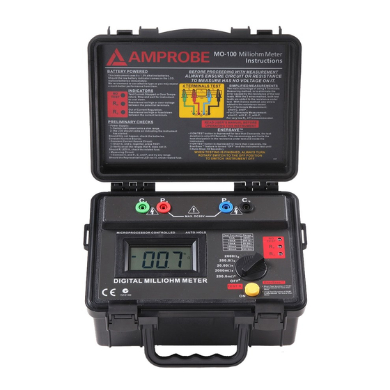
- Page 4 MO-100 Milliohm Meter Current Injection Terminals Potential Injection Terminals Meet LVD & EMC requirement Liquid Crystal Display Rotary Selector Switch Start / Stop Test Over Temperature indicator. Lit = Over-temperature or test stopped. Resistance between the current leads too high (fuse!).
-
Page 5: Table Of Contents
MO-100 Milliohm Meter CONTENTS SYMBOLS .......................2 CAUTIONS AND PRECAUTIONS ................2 UNPACKING AND INSPECTION ................3 INTRODUCTION .....................4 OPERATION ......................6 Preparation For Use ..................6 Check the Battery .....................6 Check the Current Regulation .................6 Check the Voltage Measurement ..............6 Measuring ......................7 Test Leads ......................8 Supplied Potential Test Leads ................8... -
Page 6: Symbols
SYMBOLS � Caution ! Refer to the explanation in this Manual � Caution, Risk of Electric Shock Please remove all the test leads before performing maintenance, � cleaning, battery replacement, fuse replacement, etc � Conforms to relevant Australian standards � Complies with European Directives Do not dispose of this clamp meter as unsorted municipal waste. -
Page 7: Unpacking And Inspection
0°C the operation of the LCD will be sluggish Warning, risk of electric shock. � UNPACKING AND INSPECTION Your shipping carton should include: MO-100 Milliohm Meter Shoulder Belt Test Lead (Green Color) Test Lead (Red Color) Test Lead (Blue Color) Test Lead (Black Color) Alkaline Battery (SIZE AA, 1.5V) -
Page 8: Introduction
INTRODUCTION • The Milliohm Meter is a battery operated instrument wich supply a low current to the circuit under test, with which, stable, accurate measurement of low resistance can be made, still, over a wide range of values. • Resolution on the lowest range is 100μ ohm and on the highest range, 1 ohm. - Page 9 • This crowbar is activated by voltage. If the voltage is too high, that crowbar will blow the fuse automatically to interrupt the circuit. • The voltage between P1 and P2 is also protected for over voltage but does not have a fuse. •...
-
Page 10: Operation
OPERATION Preparation For Use When unpacked, the tester should be inspected for any visible signs of damage, and the preliminary checks described in the user’s manual should be performed to ensure that it is operating correctly. If there is any sign of damage, or if the instrument does not operate correctly, return it to your nearest supplier. -
Page 11: Measuring
Measuring • Perform the preliminary checks before proceeding with measurement and ensure that the precautions listed are observed. • Connect the test leads (color coded) to the instrument as shown. • The current test leads must always be outside of the potential test leads. •... -
Page 12: Test Leads
Test Leads The test leads supplied with the instrument are suitable for connecting to conductors up to 17mm in diameter or bus bars 17mm tick. There will be, instances where the item being measured require larger jaws, and the user is advised to make up his own leads. -
Page 13: Thermal Effects
Thermal Effects • Temperature can have a significant effect on the performance of a milliohm meter due to the temperature coefficient of the resistance under test and thermal EMF’s across the dissimilar conductors. • Most conductors have a large temperature coefficient of resistance. For example: 0.4%/°C for copper. -
Page 14: Specification
SPECIFICATION Electrical Measuring Ranges : 0 - 200.0m ohms in steps of 100μ ohm 0 - 2000m ohms in steps of 1m ohm 0 - 20.00 ohms in steps of 10m ohm 0 - 200.0 ohms in steps of 100m ohm 0 - 2000 ohms in steps of 1 ohm Accuracy : ±0.5% of reading ±2 digits over the... -
Page 15: Rated Environmental Conditions
Rated Environmental Conditions 1. Indoor Use 2. Pollution Degree 2 3. Altitude up to 2000 meter 4. Relative humidity 80% max 5. Ambient temperature 0°C ~ 40°C � - EMC: Conforms to EN61326-1. This product complies with requirements of the following European Community Directives: 89/ 336/ EEC (Electromagnetic Compatibility) and 73/ 23/ EEC (Low Voltage) as amended by 93/ 68/ EEC (CE Marking). -
Page 16: Maintenance And Repair
MAINTENANCE AND REPAIR If there appears to be a malfunction during the operation of the meter, the following steps should be performed in order to isolate the cause of the problem. 1. Check the battery. Replace the battery immediately when the symbol “N”... -
Page 17: Fuses Replacement
FUSES REPLACEMENT The maximum continuous voltage which can be applied across the potential and current leads is around 10.7V. Applying more than that voltage will automatically blow their respective fuses. However, the crowbar trigger can be factory adjusted for your application. We have specially selected that method to stop damaging the instrument, should it be misused There are three fuses:... - Page 18 Current Circuit Fuse(F2) • Potential Circuit Fuse Fuse protection is provided on the potential terminals. This fuse is situated under the Printed Circuit Board. To access it, you need to unscrew the four mounting screws which are holding the font panel. Two of these screws are located under the foots, and the two others are located inside the battery compartment.
Need help?
Do you have a question about the MO-100 and is the answer not in the manual?
Questions and answers