
Related Manuals for Amprobe AT-3500


Summary of Contents for Amprobe AT-3500
- Page 1 AT-3500 Underground Cable/Pipe Locator System Users Manual • Mode d’emploi • Bedienungshandbuch • Manuale d’Uso • Manual de uso • Användarhandbok...
- Page 3 AT-3500 Underground Cable/Pipe Locator System Users Manual AT3500_Rev001 © 2009 Amprobe Test Tools. All rights reserved.
- Page 4 Please read the warranty statement and check your battery before requesting repair. During the warranty period any defective test tool can be returned to your Amprobe® Test Tools distributor for an exchange for the same or like product. Please check the “Where to Buy”...
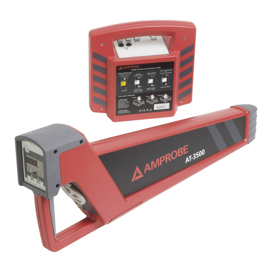
- Page 5 ➊ Control Panel with display ➋ Speaker with Volume control Quieter Louder ➌ Headphone jack (3.5 mm headphone not included) ➍ Battery Compartment ➎ Floor Cap (Removable) R-3500 Receiver ➊ Light Sensor: Automatically regulates the brightness of the display ➋ ON/OFF Switch ➌...
-
Page 6: Table Of Contents
AT-3500 Underground Cable/Pipe Locator System CoNTENTS Unpacking And Inspection ..................................5 Introduction ........................................ 5 Operation ........................................5 Applications and principles of direct coupling ............................6 Direct Coupling ..................................... 7 Direct Coupling using the A-3500 Clamp ............................7 Inductive Coupling ....................................7 Locating Passive Lines (Radio and Power Modes) .......................... -
Page 7: Unpacking And Inspection
Nylon Bag INTRodUCTIoN The AT-3500 underground cable/pipe locator system is designed for the uncomplicated and user-friendly determination of the location, orientation and depth of metallic lines (e.g. cable and pipe lines). It can be used to probe areas for unknown lines or for locating specific lines. -
Page 8: Applications And Principles Of Direct Coupling
Push button to save the setting. • An audible sound is heard • The display shows the main menu: Push Control3 to select the mode of operation • Radio for locating cables carrying VLF re-radiated radio signals (No need for T-3500) •... -
Page 9: Direct Coupling
Adjacent lines which are horizontal to each other Minimum of the reception signal Lines situated on top of each other vertically Maximum of the reception signal direct Coupling (Refer to Fig. 2.) Connect the red test lead of the T-3500 transmitter with the conductor to be traced Connect the black test lead of the T-3500 transmitter to ground using the grounding rod. -
Page 10: Error Messages During A Depth Measurement
The receiver was moved too far to the left or right while making a rough estimate. Move in the opposite direction until the following symbol appears: TECHNICAL SPECIFICATIoNS R-3500 The following parameters are specified for the R-3500 receiver: Frequency ranges • Range 1: radio 15 kHz to 23 kHz • Range 2: power network 50 Hz / 60 Hz; optionally 100 Hz (can be adjusted by Amprobe service personnel) • Range 3: transmitter 32.768 kHz Sensitivity at a depth of 1m • Range 1: radio >20 µA • Range 2: power network >7 mA • Range 3: transmitter >5 µA... -
Page 11: Maintenance
• Resolution 0.1 m • Accuracy - Range 1: radio ±20 % - Range 2: power network ±20 % - Range 3: transmitter ±5 % (>5m (6-FT)), ±20 % (<5m (15-FT)) Power supply 10 x IEC R6 / AA cell / Mignon Operating time 40 hours (for intermittent use with alkaline batteries, 20 °C) Temperature range in accordance with DIN EN 60068-1 • Operation -20 °C to +55 °C... -
Page 12: Changing The Batteries In The T-3500 Transmitter
In order to replace the ten 1.5 V mignon (AA) batteries, the battery housing must be removed as described in the following illustrations: Changing the batteries in the T-3500 transmitter The batteries in the transmitter have to be replaced as soon as the red LED battery indicator starts to blink. Should this occur while the user is busy locating a line with the receiver, he/she will be informed of the weak batteries via the reception signal: Ty pe of signal... -
Page 13: Changing The Floor Cap On The R-3500 Receiver
Changing the floor cap on the R-3500 receiver The plastic floor cap, which prevents the tip of the receiver from being damaged, can be easily replaced with the aid of a pointed object (e.g. screw driver). Replacements can be ordered through the SEBA KMT sales team. - Page 14 Fig. 1 Fig. 2 Fig. 3...
- Page 15 Fig. 4 Fig. 5 Fig. 6...
- Page 16 Fig. 7...
Need help?
Do you have a question about the AT-3500 and is the answer not in the manual?
Questions and answers