Table of Contents
Advertisement
Advertisement
Table of Contents
Troubleshooting

Related Manuals for Mindray PM-60


Summary of Contents for Mindray PM-60
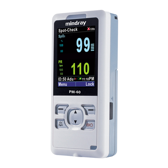
- Page 1 Pulse Oximeter Service Manual...
- Page 3 Preface Manual Purpose This manual provides detailed information about the assembling, dissembling, testing and troubleshooting of the equipment to support effective troubleshooting and repair. It is not intended to be a comprehensive, in-depth explanation of the product architecture or technical implementation.
- Page 4 FOR YOUR NOTES...
-
Page 5: Table Of Contents
Contents 1 Safety ..........................1-1 1.1 Safety Information ......................1-1 1.1.1 Dangers ......................1-2 1.1.2 Warnings......................1-2 1.1.3 Cautions ......................1-2 1.1.4 Notes ........................1-2 1.2 Equipment Symbols ......................1-3 2 Theory of Operation ......................2-1 2.1 Introduction........................2-1 2.2 System Connections ......................2-1 2.2.1 Mounting the Pulse Oximeter ................ - Page 6 4.2 Part Replacement ......................4-1 4.3 Software Version Check ....................4-2 4.4 Technical Alarm Check ....................4-2 4.5 Troubleshooting Guide....................4-3 4.5.1 Power On/Off Failures ..................4-3 4.5.2 Display Failures ....................4-3 4.5.3 Alarm Problems....................4-4 4.5.4 Button Failure..................... 4-4 4.5.5 Interface Failures....................
-
Page 7: Safety
Safety 1.1 Safety Information DANGER Indicates an imminent hazard that, if not avoided, will result in death or serious injury. WARNING Indicates a potential hazard or unsafe practice that, if not avoided, could result in death or serious injury. CAUTION Indicates a potential hazard or unsafe practice that, if not avoided, could result in death or serious injury. -
Page 8: Dangers
1.1.1 Dangers There are no dangers that refer to the maintenance in general. Specific “Danger” statements may be given in the respective sections of this manual. 1.1.2 Warnings WARNING All installation operations, expansions, changes, modifications and repairs of this product should be conducted by authorized personnel only. Always disconnect the equipment with the charger stand and remove the batteries before disassembling the equipment. -
Page 9: Equipment Symbols
1.2 Equipment Symbols Direct Current (DC) Attention: Consult this manual before maintenance. Auxiliary output connector Audio pause Battery door locked/unlocked Power supply connector Left/Right button Power button Up button Down button Date of manufacture Serial number Safety Class II equipment Type BF applied part, defibrillation protected The following definition of the WEEE label applies to EU member states only. - Page 10 FOR YOUR NOTES...
-
Page 11: Theory Of Operation
Theory of Operation 2.1 Introduction This pulse oximeter is designed to monitor or measure the oxygen saturation and pulse rate of single adult, pediatric and neonatal patient. The pulse oximeter also: Presents audible and visual alarms in case of patient or equipment problems. Enables the real-time displaying, reviewing, storing and exporting of SpO and PR values. -
Page 12: Connectors For Peripheral Devices
2.2.2 Connectors for Peripheral Devices The connectors for peripheral devices are located at the top, right side and bottom of the pulse oximeter as shown in the figure. Multifunctional connector It is a DB 9 connector which is used to connector a SpO sensor (including reusable sensor, disposable sensor and veterinary sensor) to measure the oxygen saturation or connect a personal computer through a PC communication cable to export trend data. -
Page 13: Main Unit
2.3 Main Unit The pulse oximeter consists of main board, SpO board, display, speaker, batteries and charger stand. The main board is composed of a main control unit and a power module. The following diagram shows the structure of the main unit. 2.3.1 Main Control Unit The main control unit provides the system with resources and support. -
Page 14: Power Supply
2.3.1.1 Power Supply The power module provides the main control unit with 3.1 V, 2.5 V and 0.9 V power supple. Label Voltage Applicable parts DVDD 3.1 V Alarm LEDs, Flash memory, infrared light-emitting IC, PC communication cable, LCD boost up circuit, prestage audio optional amplifier. - Page 15 2.3.1.2 Core Control Unit The Core control unit consists of CPU, SDRAM and Flash memory. The CPU is ADI’s DSP BF531. Its kernel running frequency is up to 400 MHz and external frequency up to 133MHz. The kernel voltage is 0.8 V and the current consumed at 50 MHz is as low as 26mA.
- Page 16 Audible indicators Audio files including alarm tone, button tone and pulse tone are burned in a serial flash memory in advance. To give out a sound, the CPU reads audio data from the flash memory and controls the puse-width modulation (PWM) to give out a audible signal. The pulse oximeter supports pitch tone and multi-level volume.
- Page 17 2.3.2.1 Input The pulse oximeter runs on a chargeable lithium-ion battery or three alkaline AA size batteries. Lithium-ion battery: voltage 3.7V, capacity 1800mAh; Alkaline AA size batteries: three batteries in series, the total voltage 4.5V. Connect the pulse oximeter to the charger stand and then connect the AC mains. The battery will be charged automatically if a lithium-ion battery is used.
- Page 18 2.3.2.4 Charging the Lithium-ion Battery The pulse oximeter is configured with a lithium-ion battery charging circuit which can detect battery charging status and provide protection against overtime, overcurrent as well as overtemperature charging. It automatically charges the battery in circle and enters into the sleeping mode when the battery is fully charged.
-
Page 19: Main Board Interfaces
2.3.3 Main Board Interfaces The main board implements connection and communication with other parts and peripheral devices. The interfaces located on the main board are listed below: Description What to connect LCD connector LCD screen board, providing power supply and board connector communicating the SpO board... -
Page 20: Spo 2 Module
2.3.4 SpO Module The SpO module measures oxygen saturation and pulse rate and offers Pleth wave and perfusion strength. It also offers motion and poor perfusion proof, detects status and fault, and communicates with the main control unit. The SpO module block diagram is shown below: 2-10... -
Page 21: Charger Stand
2.3.4.1 Analog Circuit The SpO module analog circuit adopts low power consumption design. The voltage of signal amplifying part is ±2.5V. The first stage amplifying multiple is adjustable. The sensor's driving voltage is 3.3V. 2.3.4.2 Digital Circuit The digital circuit part mainly consists of microprocessor circuit and watchdog circuit. The ADuC7024 microprocessor used on the SpO module is AD’s 16/32-bit MCU. - Page 22 FOR YOUR NOTES 2-12...
-
Page 23: Testing And Maintenance
Testing and Maintenance 3.1 Introduction To ensure the pulse oximeter always functions normally, qualified service personnel should perform regular inspection, maintenance and test. This chapter provides testing procedures for the pulse oximeter with recommended test equipment and frequency. The service personnel should perform the testing and maintenance procedures as required and use appropriate test equipment. -
Page 24: Test Report
3.1.1 Test Report After completing the tests, service personnel are required to record test results in the following table and report them to our Customer Service Department. Test Equipment Name Model/PN Expiry Date Test Record Test item Test point Test Results Conclusion Pass/Fail: Tested by:... -
Page 25: Visual Test
3.2 Visual Test Inspect the equipment for obvious signs of damage. The test is passed if the equipment has no obvious signs of damage. Follow these guidelines when inspecting the equipment: Carefully inspect the case, the display screen and the buttons for physical damage. Inspect all external connections for loose connectors, bent pins or frayed cables. -
Page 26: Performance Tests
3.4 Performance Tests 3.4.1 SpO Test Required tool: SpO simulator Connect the pulse oximeter with the SpO sensor. Connect the SpO sensor with the SpO simulator. Select the model and manufacturer of the SpO module under test; set SpO to 96% and PR to 80 bmp. -
Page 27: Electrical Safety Tests
3.5 Electrical Safety Tests WARNING Electrical safety tests are a proven means of verifying the electrical safety of the equipment. They are intended for determining potential electrical hazards. Failure to find out these hazards timely may cause personnel injury. Commercially available test equipment such as safety analyzer, etc. can be used for electrical safety tests. -
Page 28: Enclosure Leakage Current Test
A: AC mains (programmable and frequency adjustable) Isolation transformer on the leakage current testing apparatus Safety analyzer D: Unit under test Tools required: Safety analyzer Isolation transformer 3.5.1 Enclosure Leakage Current Test Connect the 601 safety analyzer to an AC power supply (264 V, 60 Hz). Connect the SpO sensor to the RA terminal of the 601 safety analyzer. -
Page 29: Output Interface Test
3.6 Output Interface Test 3.6.1 RS232 Port test Use a PC communication cable to connect the multifunctional connector of the pulse oximeter under test with the RS232 port of a personal computer. Select [Menu]→[Trend] to enter the trend window. Press the Left button to enter the [Trend Setup] menu. Set [Export Port] to [Wire]. -
Page 30: Program Upgrade
3.7 Program Upgrade You can upgrade the pulse oximeter software by downloading the upgrade software through a serial port. The upgrade software can run directly on a personal computer. You can upgrade the following programs by connecting the pulse oximeter with the personal computer through a PC communication cable: Bootstrap program System program... -
Page 31: Troubleshooting
Troubleshooting 4.1 Introduction In this chapter, problems are listed along with possible causes and recommended corrective actions. Refer to the tables to check the pulse oximeter, identify and eliminate the troubles. The troubles we list here are frequently arisen difficulties and the actions we recommend can correct most problems, but not all of them. -
Page 32: Software Version Check
4.3 Software Version Check Some troubleshooting tasks may require you to identify the configuration and software version of your pulse oximeter for software compatibility. For detailed information on version compatibility, contact our Customer Service Department. To check the version information, Select [Menu]→[System]→[Maintenance >>]→enter required password→[Version >>]. -
Page 33: Troubleshooting Guide
4.5 Troubleshooting Guide 4.5.1 Power On/Off Failures Symptom Possible Causes Corrective Actions The pulse oximeter Batteries are not Install batteries and then check if the pulse fails to start. installed; oximeter can be powered on. The pulse oximeter is turned on when being connected with the charger stand. -
Page 34: Alarm Problems
4.5.3 Alarm Problems Symptoms Possible Causes Corrective Actions Alarm lamp does Main board defective Replace the main board. not light or extinguish but alarm sound is issued. No alarm sound is Alarm volume is set to Select [Menu]→[Normal Setup]; adjust [Alm issued but alarm zero. -
Page 35: Power Supply Failures
4.5.6 Power Supply Failures Symptoms Possible Causes Corrective Actions Battery cannot be Battery defective Replace the battery fully charged. Main board defective Replace the main board. Battery cannot be Battery defective Replace the battery charged. Charger stand fails Replace the charger stand. Main board defective Replace the main board. - Page 36 FOR YOUR NOTES...
-
Page 37: Repair And Disassembly
Repair and Disassembly 5.1 Tools The following tools may be required for disassembly and repair: Small screwdriver Sharp-nose pliers Tweezers 5.2 Preparations for Disassembly Before disassembling the pulse oximeter, stop monitoring the patient, turn off the pulse oximeter and disconnect all the accessories and peripheral devices. CAUTION Before disassembling the pulse oximeter, be sure to eliminate the static charges first. -
Page 38: Disassembly Guide
5.3 Disassembly Guide 5.3.1 Removing the Covers As shown in the figure, rotate the battery door key for 90° to loose the lock pin that secures the battery door. Open the battery door and remove the batteries. - Page 39 Remove the adjusting bracket. Unscrew 2 M2X6 crosshead screws and 3 PT2X8 tapping screws. Separate the front panel from the rear cover with your hands. NOTE Carefully separate the covers to avoid damage the wires and connectors.
-
Page 40: Removing The Main Board
5.3.2 Removing the Main Board To remove the main board, disconnect the speaker cable and the SpO communication. 5.3.3 Removing the Speaker and SpO Communication Cable Socket Unscrew 3 PT2X8 tapping screws and remove the speaker. -
Page 41: Removing The Lcd Screen
Thrust the end of the SpO communication cable socket and push it out. 5.3.4 Removing the LCD Screen Pry the LCD screen at the top right corner with tweezers, disconnect the flexible cable socket and remove the LCD screen. -
Page 42: Remove The Screen Mount
CAUTION Do not touch the LCD screen. Disassemble the LCD screen in an environment as dust-free as possible. 5.3.5 Remove the Screen Mount Use sharp-nose pliers to straighten the three clips that secure the screen mount to the main board. Remove the screen mount. -
Page 43: Parts
Parts 6.1 Introduction This chapter contains the exploded views and parts lists of the pulse oximeter. It helps the service personnel to identify the parts during disassembling the pulse oximeter and replacing the parts. The architecture of the pulse oximeter main unit is shown below: Main unit Front panel Rear cover... -
Page 44: Main Unit
6.2 Main Unit Exploded View Parts List Description 0852-20-77413 Screen lens 0852-30-77449 Front panel assembly 0852-30-77450 Main unit assembly 0852-20-77409 IR lens 0852-20-77452 Rear Cover assembly M04-002405--- Crosshead screw M2X6 M04-051060--- Tapping screw PT2X8 Battery adjusting bracket assembly (for AA size 0852-30-77451 batteries) 0852-20-77411... -
Page 45: Front Panel Assembly
6.3 Front Panel Assembly Exploded View Parts List Description 0852-20-77402 Front panel 0852-20-77417 DC-IN waterproof pad 0852-20-77404 DC-IN lens 0852-20-77414 Screen fixture 1 0852-20-77406 Waterproof frame 0852-20-77405 Button 0852-20-77403 Alarm LED cover... -
Page 46: Main Board Assembly
6.4 Main Board Assembly Exploded View Parts List Description 0000-10-11253 LCD screen 0852-20-77415 Screen fixture 2 0852-20-77423 LCD mount 0852-20-77426 Compression nut 0852-30-77428 Main board 0852-30-77454 SpO2 module signal detection board... -
Page 47: Battery Adjusting Bracket Assembly
6.5 Battery Adjusting Bracket Assembly Exploded View Parts List Description 0852-20-77422 Leaf 5 0852-20-77421 Leaf 4 0852-20-77408 Battery adjusting bracket... -
Page 48: Rear Cover Assembly
6.6 Rear Cover Assembly Exploded View Parts List Description 0000-10-43076 Speaker 0850-20-30708 Socket fixture M04-051060--- Tapping screw M2X8 0852-20-77425 Waterproof seal 2 M04-021000--- Flat washer 0852-2077432 Spring 0852-20-77407 Rear cover 0852-20-77410 Lock pin 0852-20-77420 Leaf 3... -
Page 49: Replacement Parts
0852-20-77419 Leaf 2 0852-20-77418 Leaf 1 0850-20-30704 /Communication cable socket 6.7 Replacement Parts To replace the parts, refer to 5 Repair and Disassembly and the exploded views in this chapter. NOTE In the list below, we list most of the replacement parts. Contact our Customer Service Department for more replacement parts. - Page 50 P/N:0852-20-77476(1.0)...
Need help?
Do you have a question about the PM-60 and is the answer not in the manual?
Questions and answers