Table of Contents
Advertisement
Quick Links
Advertisement
Table of Contents

Subscribe to Our Youtube Channel
Related Manuals for Mindray Pulse


Summary of Contents for Mindray Pulse
- Page 1 Pulse Oximeter Service Manual...
- Page 3 National Standards; is operated under strict observance of this manual. device Note This device is not intended for home use. Pulse oximeter Service Manual (V1.1)
- Page 4 It is important for the hospital or organization that uses this equipment to carry out a reasonable maintenance schedule. Failure to do so may result in equipment failure, or injury to the patient or operators. Pulse oximeter Service Manual (V1.1)
- Page 5 In the event that it becomes necessary to return a unit to our company, follow the instructions below. 1. Obtain a return authorization. Contact our company to obtain a Customer Service Authorization number. This number Pulse oximeter Service Manual (V1.1)
- Page 6 It is important for the hospital or organization that uses this equipment to carry out a reasonable maintenance schedule. Failure to do so may result in equipment failure, or injury to the patient or operators. Pulse oximeter Service Manual (V1.1)
- Page 7 This symbol indicates the dual-purpose socket can connect with the PC communication cable. Illustrations All illustrations in this manual are provided as examples only. They may not necessarily reflect your setup or data displayed on your Pulse Oximeter. Pulse oximeter Service Manual (V1.1)
-
Page 9: Table Of Contents
4.3 Disposable SpO sensor/transducer ................4-2 Chapter 5 Test and Prompt List ..................5-1 5.1 Test Procedure ......................5-1 5.2 Prompt List .........................5-2 Chapter 6 Maintenance and Cleaning ................6-1 6.1 Maintenance.......................6-1 6.2 Cleaning ........................6-1 6.3 Disinfection & Sterilization ..................6-2 Pulse oximeter Service Manual (V1.1) -
Page 11: Chapter 1 Introduction
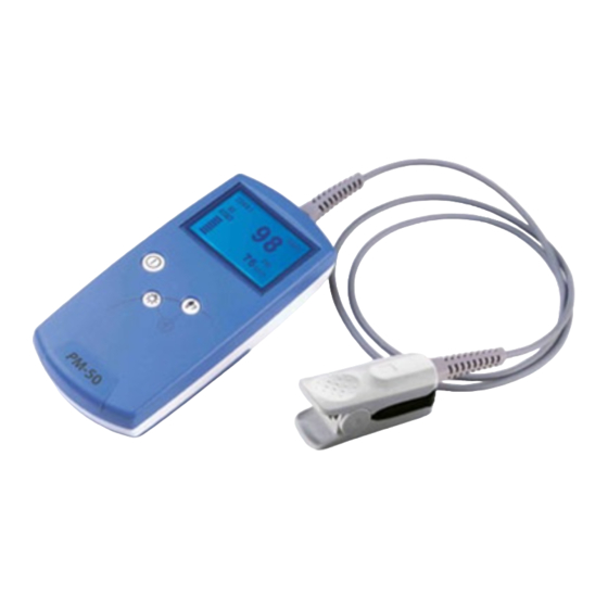
(PR) and pulse strength. The Pulse Oximeter employs a finger SpO2 sensor to measure patient’s SpO2, PR and pulse strength, and all of these are displayed on the LCD screen. The Pulse Oximeter is operated and controlled by three buttons, which are Power Button, Backlight Button and ID Confirm Button. -
Page 13: Chapter 2 Circuit Principle
(SpO2 values) on the LCD screen. Pulse-strength bar, battery remained capacity and data export indication are also shown on the screen. Pulse Oximeter can be connected with PC through serial port for data transportation and the data can be printed out from PC. - Page 14 Fig 2-2 Watchdog Circuit 2.1.1.3 Data Storage The Pulse Oximeter requires automatic data storage in case of power supply failure. 24WC64 IC with the capacity of 8K bytes was adopted. This IC uses I C bus. The C111 and C112 act as filter capacitors to reduce the influence from high frequency noise.
- Page 15 Fig 2-4 DA Circuit 2.1.1.5 Pulse Oximeter uses MAX1290 as the ADC, which of 12-bit resolution and 8 channels and parallel interface. Two signals of SIGNAL and PROBE-DET are collected by the chip. They directly enter the channel 0 and channel 1 of the ADC without analog switch.
- Page 16 2.1.1.7 Switch ON/OFF Delay Circuit Pulse Oximeter has no delay for switch on, but there is 2s delay for switch off. In the delay circuit, a voltage of +7V is slowly supply to the Q5. The RC network on Q4’s base is used to eliminate the button-press shaking and to protect the circuit from electrostatic charge.
- Page 17 PCON signal, which directly controls the ON/OFF. Resistor R111 is necessary for the AND logic circuit. R95, C82 and E12 form a RC filtering network to protect the circuit from electrostatic charge. Fig 2-7 Switch On Circuit Pulse oximeter Service Manual (V1.1)
- Page 18 Fig 2-8 Serial Signal Voltage Level Conversion Circuit 2.1.1.9 Button Circuit Pulse Oximeter has three buttons, Power Button, ID Confirm Button and LCD Backlight Button. The circuit is shown as below: Fig 2-9 Button Circuit R82 and C81 form RC filter circuit and can resist electrostatic charge interference. The resistance of R82 is 4.7K, which can protect the circuit with big current.
-
Page 19: Reliability Design
Circuit Principle 2.1.1.10 Voltage Detect Pulse Oximeter requires that the battery voltage and +7V be detected all the time. S1C33209 has 8 10-bit AD channels, two of which were used. S1C33209 cannot stand that high voltage, so, a voltage divider was adopted to convert the monitored voltages to the range S1C33209 can detect. - Page 20 Circuit Principle The following protections are used for EMC design in Pulse Oximeter: Every IC has one by-pass capacitor, some ICs have different rating capacitors to enlarge the filter band; Serial resistors on the communication lines connected with the PC, to reduce the interference propagation;...
-
Page 21: Chapter 3 Specifications
EMC type Class A 3.2 General Specifications Type of patients Adult, pediatrics, neonate Parameter monitored SpO2, pulse rate (PR) and pulse strength Data interface Multiplex interface: SpO2 and PC communication cable Display screen Dot matrix LCD Display area Not less than 42mm×35mm... -
Page 22: Electrical Specifications
15h for alkaline battery 3.6 SpO &PR Specifications SpO2 measurement range 0%~100% SpO2 resolution SpO2 accuracy Adult/ Pediatric 70%- 100%:±2% Neonate 70%- 100%:±3% 0%- 69%: No specified PR measurement range 25~254bpm PR resolution 1bpm PR accuracy ±2bpm Pulse oximeter Service Manual (V1.0) -
Page 23: Chapter 4 Structure
Structure Chapter 4 Structure 4.1.1 Explosive diagram Fig 4-1 Pulse Oximeter Explosive diagram(0850-30-30752) Table 1 Parts list Description 0850-20-30705 Screen cover 0850-20-30700 or other Front housing Pulse oximeter Service Manual (V1.1) -
Page 24: Batteries Installation And Maintenance
Anode contact spring 4.2 Batteries Installation and Maintenance 4.2.1 Install Batteries The Pulse Oximeter is operated by four 1.5V AA batteries. Follow the steps below to install batteries before use: Hold the Pulse Oximeter face-down firmly by one hand. Push the battery cover gently by the other hand along the vertical direction of Pulse Oximeter. -
Page 25: Disposable Spo Sensor/Transducer
Pediatric, 2211-2, ’ENVITE’ 0010-10-12334 Infant, 2211-5, ’ENVITE’ 0010-10-12335 Neonate, 2211-6, ’ENVITE’ 0010-10-12336 NELLCOR MAX-A, Adult (>30Kg) 0010-10-12202 NELLCOR MAX-P, Pediatric (10~50Kg) 0010-10-12203 NELLCOR MAX-I, Infant (3~20Kg) 0010-10-12204 NELLCOR MAX-N, Neonate / Adult (<3Kg 或 0010-10-12205 >40Kg) Pulse oximeter Service Manual (V1.1) -
Page 27: Chapter 5 Test And Prompt List
5.1.4 Communication with PC Connect the Pulse Oximeter with a PC (RS-232 port) by a cable. The data can be sent to PC. 5.2 Prompt List Table 5-1 Prompt Information on LCD... - Page 28 Solution Error Message Cause Initiate Error Shut down the device (if can’t, remove the Failed self-test batteries) and contact Mindray for service. Please Release Check for jammed button. If problem remains, Button error the Button contact Mindray for service. Pulse Not Found Pulse not Check the patient and alert the doctor.
-
Page 29: Chapter 6 Maintenance And Cleaning
Inspect the Pulse Oximeter for possible damage during shipment; Check all the cables joint part and accessories; Test all the functions applicable to the patients and assure the Pulse Oximeter in right states. If the equipment shows any signs of malfunction, do not carry out any measurement on the patient and contact with the biomedicine engineer in the hospital or the Mindray service engineer immediately. -
Page 30: Disinfection & Sterilization
Sterilization may damage the equipment, so, it is not advised to do unless necessary in the hospital’s maintenance plan. Cleaning is recommended before sterilization. Refer to the Instructions for use for the sterilization of SpO2 sensor. Do not use gas(EtO)or formaldehyde to sterilize the equipment. Pulse oximeter Service Manual (V1.01) - Page 31 P/N: 0850-20-30763...
Need help?
Do you have a question about the Pulse and is the answer not in the manual?
Questions and answers