
Related Manuals for Mindray Passport 2LT


Summary of Contents for Mindray Passport 2LT
- Page 1 O p e r a t i n g I n s t r u c t i o n s Datascope Passport ® Datascope Passport ® 0070-01-0440-01_revD_ops color.indd 1 4/8/10 11:43:13 AM...
- Page 2 O p e r a t i n g I n s t r u c t i o n s Datascope Passport ® Datascope Passport ®...
- Page 3 Velcro Industries B.V. © Copyright Mindray DS USA. Inc.,, 2005. All rights reserved. Contents of this publication may not be reproduced in any form without permission of Mindray DS USA. Inc., 0070-10-0649-01 Passport 2®/Passport 2 LT™ Operating Instructions...
-
Page 4: Table Of Contents
Table of Contents Foreword ............................... vii Warnings, Precautions And Notes ........................vii Warnings ..............................viii Precautions ..............................xii Notes ................................xv Intended Use ..............................xvi Unpacking ..............................xvi Symbols and Descriptions ..........................xvii General Description ......................1 - 1 Controls, Indicators and Connectors .................. 2 - 1 Front Panel.............................. - Page 5 Table of Contents “ECG Lead Fault” Message ........................3 - 24 12-Lead ECG Monitoring (Optional Passport 2)................... 3 - 24 12-lead ECG Analysis (Optional Passport 2) ..................3 - 25 Invasive Blood Pressure (IBP1, IBP2) (optional Passport 2) ..................3 - 26 Pulse Oximetry ............................
- Page 6 Table of Contents Respiration Monitoring on the Passport 2....................3 - 54 Thoracic Impedance ........................3 - 54 ® Waveform (requires optional Microstream or Gas Module) (Passport 2 only) ......3 - 54 ® Microstream Monitoring (Optional Passport 2)..................3 - 55 Microstream CO ............................
- Page 7 Table of Contents NIBP Accessories............................. 5 - 1 Oximetry Sensors and Accessories......................5 - 2 ® ® Pulse Oximetry-Masimo SET LNOP ..................5 - 2 ® ® Pulse Oximetry-Masimo Set LNCS ..................5 - 3 ® ® Pulse Oximetry-Nellcor OxiMax * ..................
- Page 8 Table of Contents NIBP Measurement Cycle ......................... 6 - 13 IBP Parameter Sub-System Performance Characteristics................. 6 - 14 IBP Performance Requirements ......................6 - 14 IBP Connector Type ......................... 6 - 14 IBP Transducer Performance ......................6 - 14 IBP Heart Rate Meter ........................6 - 14 Temperature Parameter Performance Characteristics ..................
- Page 9 Newborn NIBP Technique..........................6 - 41 How To Get Help............................6 - 41 Warranty............................... 6 - 42 USA, Canada, Mexico, and Puerto Rico..................... 6 - 42 Mindray DS’s Responsibility ..........................6 - 43 Extended Warranty............................6 - 43 0070-10-0649-01 Passport 2®/Passport 2 LT™ Operating Instructions...
-
Page 10: Foreword
General knowledge of monitoring and an understanding of the features and functions of the Mindray DS Passport 2/Passport 2 LT Monitor are prerequisites for its proper use. Do not operate this monitor before reading these instructions. -
Page 11: Warnings
Introduction Warnings Warnings WARNING: Internal Electrical Shock Hazard - This unit does not contain any user-serviceable parts. Do not remove instrument covers. Refer Servicing to qualified personnel. WARNING: Trace Gas Hazard - When using the optional Gas Module, a health hazard exists when trace amounts of vaporized anesthetic agents are chronically inspired by operating room personnel. - Page 12 WARNING: The use of gas sampling accessories in Gas Module 3 other than specified by Mindray DS may cause significant measurement errors and patient risk. Passport 2®/Passport 2 LT™ Operating Instructions...
- Page 13 Introduction Warnings WARNING: Use of accessories, transducers and cables other than those specified in the manual may result in increased Electromagnetic Emissions or decreased Electromagnetic Immunity of the Gas Module 3. WARNING: With the exception of stacking on a Gas Module with the appropriate mounting brackets, the Passport 2/Passport 2 LT should not be used adjacent to or stacked with other equipment.
- Page 14 Warnings Introduction WARNING: Do not clean the Gas Module while it is on and/or plugged ™ WARNING: Connect only DRYLINE gas sampling lines to the water trap. Note that there may be other compatible tubes present that must not be used, e.g. IV lines. ™...
-
Page 15: Precautions
CAUTION: This unit must only be operated with Mindray DS approved software. CAUTION: NIBP cuffs must be used with the correct Mindray DS hoses. See chapter 5.0 for part numbers. CAUTION: Use only Mindray DS accessories with this product. CAUTION:... - Page 16 3 Lead and 5 Lead ECG cable monitoring only. Invasive Blood Pressure triggering is not supported. ECG analog output is disabled when 12 Lead ECG analysis is enabled. CAUTION: Use only Mindray DS supplied power cords, or if a substitute is necessary, use only hospital grade power cords. ™...
- Page 17 Introduction Precautions CAUTION: To avoid permanent damage, do not expose metal components (pins, sockets, snaps) to disinfectants, soaps or chemicals. CAUTION: Observe caution on all patients (Neonates, Pediatrics, and Adults) when NIBP is set to the Continuous Mode and the 1 minute interval.
-
Page 18: Notes
Phase 4 and Phase 5 Korotkoff sounds. Reports of study findings for both the auscultatory method as well as the intra-arterial methods are available by contacting Mindray DS Technical Support (800) 288-2121, ext. 8116. NOTE: Potential hazards due to errors in software or hardware have been minimized by actions taken in accordance with IEC 60601-1-4. -
Page 19: Intended Use
• Interpretation of Resting 12 Lead ECG, for which the target population is adult only. The monitor is intended for use in the health care facility setting. The device has the capacity of interfacing with Mindray DS’s Gas Modules, displaying the measurements of Anesthetic Gases, O... -
Page 20: Symbols And Descriptions
Symbols and Descriptions Introduction Symbols and Descriptions SYMBOL DESCRIPTION SYMBOL DESCRIPTION Attention, Consult Accompanying Documents / Type B Equipment Refer to Manual Dangerous Voltage Type BF Equipment Defibrillator Proof Type BF Equipotentiality Equipment Defibrillator Proof Type CF Alternating Current (AC) Equipment Direct Current (DC) Alarm Off Icon... - Page 21 Introduction Symbols and Descriptions For Neonatal use Manufacturer’s batch number Not for Neonatal use Serial number Conformité Européenne (CE) Marking of Conformity to European Medical Device Software Version Directive. CE represents the XXXX Notified Body number xviii 0070-10-0649-01 Passport 2®/Passport 2 LT™ Operating Instructions...
-
Page 22: General Description
General Description Passport 2 Passport 2 NIBP ALARMS DISPLAY ZERO LEAD START TRENDS LIMITS STRIP STANDBY NORMAL SCREEN SIZE MUTE CONT INTERVAL FREEZE DISCHARGE PRINT MARK STOP VIEW MUTE TREND EVENT Passport 2®/Passport 2 LT™ Operating Instructions 0070-10-0649-01 1 - 1... - Page 23 General Description The Mindray DS Passport 2/Passport 2 LT is a vital signs monitor intended for intrahospital use on human patients. The Passport 2 is a six (6) trace monitor, the Passport 2 LT is a three (3) trace monitor. The unit has many features and functions, yet is ™...
- Page 24 • External Remote Color Display Available with Color TFT LCD Equipped Monitor (optional Passport 2) • External Interfaces with IABP Systems and Mindray DS’s Central Stations, Gas Module, Remote Displays, Nurse Call Systems and Serial Communications (Passport 2) • External Interfaces with IABP Systems (Passport 2 LT) Passport 2®/Passport 2 LT™...
- Page 25 General Description • Communication with hospital CIS (Clinical Information Systems) through DIAP (Mindray DS Improved ASCII Protocol, manual P/N 0070-00-0307) (Passport 2) • Inter-Monitor Patient Data Transfer (with optional accessories) • Inter-Monitor System Set-up Transfer (with optional accessories) • Mounting Kits (optional accessory) •...
-
Page 26: Controls, Indicators And Connectors
Controls, Indicators and Connectors This section of the Operating Instructions identifies and describes each control and display of the Mindray DS Passport 2/Passport 2 LT Monitor. Step-by-step instructions for operation of the monitor are provided in Section 3.0 “Operation”. Passport 2®/Passport 2 LT™ Operating Instructions... -
Page 27: Front Panel
Front Panel Controls, Indicators and Connectors Front Panel The front panel keys are used to access many main functions quickly and easily. Figure 2-1 below shows the keys and a brief explanation of each key. DISPLAY NIBP ALARMS PRINT ZERO LEAD START STANDBY... - Page 28 Controls, Indicators and Connectors Front Panel 5. (NIBP) INTERVAL Press this key to modify the NIBP interval measurement time. The choices are: Off, Cont, 1 min, 2 min, 2.5 min, 3 min, 5 min, 10 min, 15 min, 20 min, 30 min, 1 hr, 2 hrs or 4 hrs. The “Off”...
- Page 29 Front Panel Controls, Indicators and Connectors 12. (PRINT) STRIP Press this key to initiate a 16 second print out of selected waveforms on the internal printer. ™ Press this key during the printing to stop the printer. With a View 12 ECG Analysis Module installed, press the VIEW key, then press the STRIP key to initiate a 12-lead Interpretative report that will be printed at either the internal recorder or a laser printer.
- Page 30 Controls, Indicators and Connectors Front Panel 17. MARK EVENT Press this key to cause a time stamp event marker to be noted in the trend memory. If connected to a Panorama Central Station, a time stamp event marker will also be noted in the Central Station’s trend memory.
-
Page 31: Display
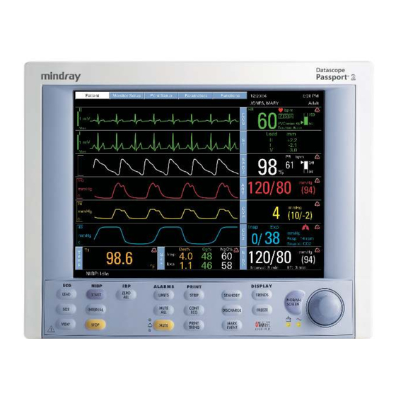
Display Controls, Indicators and Connectors Display The display of the Passport 2/Passport 2 LT provides menus, waveforms, parameter information, and messages. Figure 2-2 below shows the layout of the screen. The display can be a color LCD or monochrome flat panel for the Passport 2 monitor. The display for the Passport 2 LT is a monochrome panel. - Page 32 Controls, Indicators and Connectors Display 24. Waveform Area The waveform area is used to display the windows that contain parameter waveforms. Up to 6 waveforms can be displayed. The top window is always set to display the ECG waveform and cannot be changed. By default, SpO (Pleth) will appear as the second waveform, if connected.
- Page 33 Display Controls, Indicators and Connectors 29. Radio Icon If a Panorama Instrument Radio - 608 is installed and “WMTS Enabled” is set to “Yes” (in the Installation Menu), this icon will be displayed. 30. Panorama Icon This icon will display in one of two possible formats as follows: •...
-
Page 34: Menus
Controls, Indicators and Connectors Menus Menus The Main Menu system of the Passport 2/Passport 2 LT is available through the Menu headings, which are always displayed on the screen. The headings are accessed using the ™ Navigator Control Knob. Turning the Control Knob highlights the Menu headings one at a time. - Page 35 Menus Controls, Indicators and Connectors Patient MENU ITEM SELECTIONS DEFAULT/COMMENTS Patient Size Adult, Pediatric, Adult Neonate Gender Unspecified, Male, Default is Unspecified. Use Navigator Control Knob to Female select patient’s gender. Date of Birth Default is Unspecified. Use Navigator Control Knob to select patient’s date of birth.
-
Page 36: Monitor Setup
Controls, Indicators and Connectors Menus 2.3.2 Monitor Setup FIGURE 2-4 Monitor Setup Monitor Setup Menu MENU ITEM SELECTIONS FACTORY DEFAULT/COMMENTS Normal Screen Select to return to normal screen. Save Current A confirmation prompt appears. Select Yes to save the current settings as the “monitor” defaults. Display Setup Open an additional menu which allows you to change the positions of the parameters and... - Page 37 Menus Controls, Indicators and Connectors Monitor Setup Menu (Continued) MENU ITEM SELECTIONS FACTORY DEFAULT/COMMENTS Resp/Gas Speed 3.125, 6.25, 12.5, 12.5 mm/sec / Select to change trace speed. 25 mm/sec Advanced Setup Select to set these menu items: • Set Date •...
- Page 38 Controls, Indicators and Connectors Menus Arrhythmia Menu (Optional) FACTORY DEFAULT/ MENU ITEM SELECTIONS COMMENTS ™ Previous Menu Use Navigator Control knob to return to the previous menu. Arrhythmia All On, All Off, Factory default is All On. Use Non-lethals Off Navigator Control knob to turn arrhythmia analysis on or off.
-
Page 39: Print Setup
Menus Controls, Indicators and Connectors 2.3.3 Print Setup FIGURE 2-5 Print Setup Print Setup Menu MENU ITEM SELECTIONS DEFAULT/COMMENTS Waveform 1 ECG 1-6, IBP1,* IBP2,* ECG 1 / Select to choose Waveform 1 on the Pleth, Resp, CO printer. Agent,* N Waveform 2 Off, ECG 1-6, IBP1,* ECG 2 / Select to choose Waveform 2 on the... -
Page 40: Parameters
Controls, Indicators and Connectors Menus 2.3.4 Parameters FIGURE 2-6 Parameters Parameters Menu MENU ITEM DEFAULT/COMMENTS Select to open the respective menu. These can also be selected through the individual parameter menus. NIBP IBP1* IBP2* Resp Gases* Temperature Passport 2 only. Passport 2®/Passport 2 LT™... -
Page 41: Functions Menu
Menus Controls, Indicators and Connectors 2.3.5 Functions Menu FIGURE 2-7 Functions Menu Functions Menu MENU ITEM SELECTIONS DEFAULT/COMMENTS Normal Screen Select to return to normal screen Copy patient data to Select to copy the patient data to a data card transfer card. -
Page 42: Left Side Panel
The monitor automatically detects which probe is connected. 33. IBP 1 Connector (Optional Passport 2) A six-pin male connector used for Channel 1 Pressure Transducer connection. Mindray DS specified pressure transducers are listed in Chapter 5, Accessories. 34. IBP 2 Connector (Optional Passport 2) A six-pin male connector used for Channel 2 Pressure Transducer connection. - Page 43 37. NIBP Rectus Connector This connector is used to attach the NIBP hose to the unit. 38. ECG Connector This connector is used to attach ECG cables. Use Mindray DS cables listed in Chapter 5.0, Accessories. 39. CO Input Connector (optional Passport 2) ®...
-
Page 44: Right Side Panel
Controls, Indicators and Connectors Right Side Panel Right Side Panel FIGURE 2-9 Right Side Panel 40. PCM1 and PCM2 Card Slots These sockets are used for extended trend memory, software download to the CPU, patient ™ data transfer, monitor set-up transfers, View 12 ECG Analysis Module and Panorama Instrument Radio - 2.4. -
Page 45: Rear Panel
45. AC Receptacle Insert an AC power cord into this connector. CAUTION: Use only Mindray DS supplied power cords, or if a substitute is necessary, use only hospital grade power cords. 46. Equipotential lug Provides Equipotential grounding of hospital equipment 47. -
Page 46: Remote Color Display (Passport 2 Only)
Controls, Indicators and Connectors Remote Color Display (Passport 2 Only) Remote Color Display (Passport 2 Only) Passport 2 (with Comm Port), rear view Remote Color Display, rear view 1. Connect Interface Cable 2. Connect Passport 2 to the Analog Input Monitor Remote Color Remote Color Display Interface Cable Connector on the Remote... -
Page 47: Gas Module (Optional Passport 2)
Gas Module (Optional Passport 2) Controls, Indicators and Connectors Gas Module (Optional Passport 2) NOTE: The following models are referenced in this manual: Gas Module II, Gas Module SE, and Gas Module 3. When information is common to all models, the generic name “Gas Module”... -
Page 48: Rear Panel
4,928,692 5,758,644 4,934,372 5,769,785 8 8 8 8 - 0 0 - 1 2 3 4 - 1 2 3 4 5 Mindray DS USA Inc. Mahwah, NJ 07430 USA V 100-120~ / 220-240~ IEC 601-1:1988 ¨ CSA - C22.2 No. 601.1 - M90 UL 2601-1:1997 Mindray DS USA Inc. -
Page 49: Gas Module 3
Gas Module (Optional Passport 2) Controls, Indicators and Connectors 58. Reference Port This port is used only to measure room air. This port is not to be connected to anything. Do not block this port. 59. External Interface Port A communication interface port used to connect the Gas Module to the Passport 2. 60. -
Page 50: Rear Panel
4,928,692 5,758,644 4,934,372 5,769,785 8 8 8 8 - 0 0 - 1 2 3 4 - 1 2 3 4 5 Mindray DS USA Inc., Mahwah, NJ 07430 USA V 100-120~ / 220-240~ IEC 601-1:1988 ¨ CSA - C22.2 No. 601.1 - M90 UL 2601-1:1997 Mindray DS USA Inc.,... -
Page 51: Comm-Port (Optional Passport 2)
Comm-Port (Optional Passport 2) Controls, Indicators and Connectors Comm-Port (Optional Passport 2) NOTE: Figures 2-17 to 2-20 depict four distinct sub-models of the Comm-Port that have different interface capabilities. Only one sub-model at a time can be connected to the Passport 2. Main I/O Connector FIGURE 2-16 Comm-Port Main Connector 69. - Page 52 Controls, Indicators and Connectors Comm-Port (Optional Passport 2) FIGURE 2-18 Comm-Port 3 73. Remote Display Connector (RD1) Port used to connect a color remote display to the Passport 2 monitor 74. Nurse Call Connector (NC1) Port used to connect a Nurse Call Cable to the Passport 2 monitor LINK FIGURE 2-19 Comm-Port 4 FIGURE 2-20 Comm-Port 5...
- Page 53 Comm-Port (Optional Passport 2) Controls, Indicators and Connectors This page intentionally left blank. 2 - 28 0070-10-0649-01 Passport 2®/Passport 2 LT™ Operating Instructions...
-
Page 54: Getting Started
Operation Getting Started The Passport 2/Passport 2 LT comes with default factory settings which enable you to begin monitoring without setting any of the waveforms, parameters, alarms, or functions. However, all of these settings can be changed for specific patient or departmental needs. Certain operating characteristics are based on the selected patient size (e.g., NIBP start pressure). - Page 55 Getting Started Operation NOTE: Patient trend data is cleared if the Time and/or Date are changed on the monitor. If the Passport 2 is connected to a Panorama Central Station, the Time and Date settings of the Central Station will be acquired by the Passport 2 in one of three ways as follows: •...
-
Page 56: Installation Mode
Operation Installation Mode Installation Mode 3.2.1 Installation Menu FIGURE 3-1 Installation Menu The Installation Mode is accessed by pressing and holding the DISCHARGE key during power on. See the table that follows for descriptions of the Installation Menu choices. To enter Installation Mode proceed as follows: 1. - Page 57 Installation Mode Operation The following table describes the Installation Mode menu structure: MENU TITLE ON ACTIONS/ SCREEN MENU CHOICES DEFAULT COMMENTS Save Current Select to save current settings as defaults. Select Language Set up at factory Select to change language. Select Country Set up at factory Select to change...
- Page 58 Operation Installation Mode MENU TITLE ON ACTIONS/ SCREEN MENU CHOICES DEFAULT COMMENTS Re-boot in demo mode No, Yes Set to “YES” to start the monitor in demonstration mode on next power-up. Normal monitoring will resume after cycling power in demonstration mode. Restore factory Select to restore factory defaults...
-
Page 59: System Information Menu
Installation Mode Operation 3.2.2 System Information Menu FIGURE 3-2 System Information Menu The System Information menu is accessed by rotating the cursor to the System Information ™ selection on the Installation Menu and pressing the Navigator Control Knob. Each item on this screen is accessed in the same manner as the other menus on the monitor. - Page 60 Operation Installation Mode MENU TITLE ON MENU SCREEN CHOICES DEFAULT TEXT STRINGS Previous Menu Select to return to Previous Menu Property Of Select to set up Property name Location Select to set up Location Department Select to set up Department Contact Select to set up Contact Phone...
-
Page 61: Non-Invasive Blood Pressure Measurements (Nibp)
Non-Invasive Blood Pressure Measurements (NIBP) Operation Non-Invasive Blood Pressure Measurements (NIBP) 3.3.1 The NIBP Menu FIGURE 3-3 NIBP Menu 3.3.2 Manual NIBP Measurements 1. Select a pressure cuff that is appropriate for the size of the patient. See Optional Accessories in Section 5.1 for a detailed list of available cuffs. NOTE: A cuff that is too narrow for the limb will result in erroneously high readings. - Page 62 The cuff begins to inflate to the selected cuff pressure. After reaching the selected value the cuff begins to slowly deflate and the Mindray DS Passport 2/Passport 2 LT Monitor collects oscillometric pulsations. If the initial cuff inflation is found to be inadequate, the unit retries with a higher inflation pressure (+50 mmHg in the adult mode;...
-
Page 63: Automatic Nibp Measurements
Non-Invasive Blood Pressure Measurements (NIBP) Operation If NIBP is a selected trend source, then NIBP data will be recorded in the trend with the time stamp of the reading. If NIBP is not a selected trend source, then NIBP data will be recorded in the trend with the next entry into the trend caused by another trigger (i.e. -
Page 64: Suspension Of Nibp Measurements
Operation Non-Invasive Blood Pressure Measurements (NIBP) 3.3.3.2 Suspension of NIBP Measurements 1. Press STOP to suspend an automatically timed measurement sequence or to end a measurement cycle already in progress (deflate cuff). 2. Press START to take an immediate measurement and resume a suspended timed measurement sequence. -
Page 65: Nibp Auto Time Out Functions
Non-Invasive Blood Pressure Measurements (NIBP) Operation 3.3.7 NIBP Auto Time Out Functions The NIBP Data will time out on the display under the following conditions: • When the elapsed time exceeds the pre-set time out in the installation mode (See Section 3.2) •... -
Page 66: Ecg Measurements
CAUTION: To avoid possible damage to the Passport 2/Passport 2 LT, use only ECG cables and accessories available from Mindray CAUTION: Line Isolation Monitor transients may resemble actual cardiac waveforms, thus inhibiting heart rate alarms. Check leadwires for damage and ensure good skin contact prior to and during use. -
Page 67: Electrode Patch Location
ECG Measurements Operation 3.4.1.2 Electrode Patch Location NOTE: Store electrode patches at room temperature and open just prior to use. NOTE: Avoid more than one type of electrode on a patient because of variations in electrical resistance. NOTE: Avoid placing electrode patches directly over bone prominences or over any high activity movement areas such as shoulders or arms because muscle motion produces electrical activity. - Page 68 Operation ECG Measurements Standard 3-wire Lead Sets A 3-wire lead set can monitor one of three ECG vectors (I, II, or III). The recommended 3-wire lead placement is as follows. White Black FIGURE 3-4 3-wire Lead Placement (AHA) • Place the RA (white) electrode under the patient’s right clavicle, at the mid- clavicular line within the rib cage frame.
- Page 69 ECG Measurements Operation Standard 5-wire Lead Sets A 5-wire lead set can monitor seven ECG vectors (I, II, III, aVR, aVL, aVF, and V) simultaneously. The recommended 5-wire lead placement is as follows. White Black Brown V Lead (any position) Green FIGURE 3-5 5-wire Lead Placement (AHA) •...
- Page 70 Operation ECG Measurements ™ View 12 Card (Optional Passport 2) ™ A View 12 card utilizes a 10-wire ECG lead set that can monitor 12 ECG vectors (I, II, III, aVR, aVL, aVF, V1, V2, V3, V4, V5, and V6) simultaneously. The recommended lead ™...
- Page 71 ECG Measurements Operation Lead II Monitoring The recommended lead placement for Lead II monitoring is as follows. White Black FIGURE 3-7 Lead II Monitoring (AHA) • Place the RA (white) electrode under the patient’s right clavicle, at the mid-clavicular line within the rib cage frame.
- Page 72 Operation ECG Measurements Modified Chest Lead (MCL) Monitoring The recommended lead placement for MCL monitoring is as follows. White Black FIGURE 3-8 MCL Monitoring with a 3-wire Lead Set (AHA) • Place the RA (white) electrode under the patient’s left clavicle, at the mid-clavicular line within the rib cage frame.
- Page 73 ECG Measurements Operation Neonatal Electrode Placement Using a 3-wire lead set, ECG lead placement on a neonate is usually directed towards obtaining the best possible respiration data through the ECG thoracic impedance technique. Thoracic impedance is usually measured between the Right Arm and Left Arm electrode patches.
- Page 74 Operation ECG Measurements Monitoring a Pacemaker Patient The recommended lead placement for monitoring a pacemaker patient is as follows. Pacer White White Pacer Black Brown Black Green FIGURE 3-10 3-wire Lead Placement for a FIGURE 3-11 5-wire Lead Placement for a Pacemaker Patient (AHA) Pacemaker Patient (AHA) A pacemaker patient usually requires a different electrode patch placement configuration...
-
Page 75: The Ecg Menu
ECG Measurements Operation 3.4.2 The ECG Menu FIGURE 3-12 ECG Menu The ECG Menu provides the following choices: Normal Screen, ECG 1 — ECG 6, Arrhythmia Menu, Relearn, ST Menu, ECG Sizes Menu, ECG Setup and Resp Menu. • The Normal Screen selection returns the view to the normal screen. •... -
Page 76: Lead Or 5 Lead Ecg Measurements
This menu item is used to manually set the mode of 5 lead operation for the chosen ECG cable type. NOTE: When using Mindray DS cables, the Auto Detect selection will automatically detect the cable type and switch the mode of operation accordingly. -
Page 77: Ecg Lead Fault" Message
ECG Measurements Operation CAUTION: The Analog Output on the Passport 2/Passport 2 LT supports triggering the Intra-Aortic Balloon Pump (IABP) for 3 Lead and 5 Lead ECG cable monitoring only. Invasive Blood Pressure triggering is not supported. ECG analog output is disabled when 12 Lead ECG analysis is enabled. 3.4.4 “ECG Lead Fault”... -
Page 78: 12-Lead Ecg Analysis (Optional Passport 2)
The analysis will consist of an interpretive statement, a condition statement, and a rhythm statement as specified in the Physician’s Guide to Computerized ECG Analysis (Mindray DS P/N 0070-00-0524-01 English, 0070- 00-0524-50 all other languages). -
Page 79: Invasive Blood Pressure (Ibp1, Ibp2) (Optional Passport 2)
Invasive Blood Pressure (IBP1, IBP2) (optional Passport 2) Operation Invasive Blood Pressure (IBP1, IBP2) (optional Passport 2) 1. Plug the pressure transducer into the PRESSURE TRANSDUCER connector on the left side panel. 2. To establish a monitoring site, introduce an arterial pressure catheter into the patient’s artery in accordance with standard hospital procedures. -
Page 80: Spo 2 Pulse Oximetry
Operation Pulse Oximetry Pulse Oximetry 3.6.1 Menu ® ® Nellcor equipped unit Masimo equipped unit FIGURE 3-13 SpO Menus 3.6.2 Measurements 1. Select the appropriate sensor for the patient. 2. Attach the SpO Patient Cable to the sensor and plug the other end of the patient cable into the SpO connector located on the left side panel of the monitor. - Page 81 Pulse Oximetry Operation CAUTION: Excessive ambient light may cause inaccurate measurements. In such cases, cover the SpO sensor site with opaque material. CAUTION: Inaccurate measurements may be caused by incorrect SpO sensor application or use; significant levels of dysfunctional hemoglobins, (e.g., carboxyhemoglobin or methemoglobin); or intra-vascular dyes such as indocyanine green or methylene blue;...
-
Page 82: Performance Considerations
Operation Pulse Oximetry It is also possible to change the averaging time of the Saturation and Pulse Rate measurements. The post average time can be changed to 6, 8, 10, 12, 14 or 16 seconds. 3.6.3 Performance Considerations To ensure optimal performance, use an appropriate sensor, apply it as directed, and observe all warnings and cautions. -
Page 83: Masimo Sensors And Accessories
Pulse Oximetry Operation 3.6.4.1 Masimo Sensors and Accessories Masimo Sensors Family PART PATIENT DISPOSABLE/ SELECTION NUMBER SIZE REUSABLE ® LNOP •Adt Adult Disposable Finger 0600-00-0043-01 > 30 kg. Disposable Sensor ® LNOP •Pdt Pediatric/Slender Digit 0600-00-0044-01 10 to 50 kg. Disposable Disposable Sensor ®... -
Page 84: Cleaning And Re-Use
Operation Pulse Oximetry 3.6.4.3 Cleaning and Re-use The sensor may be reattached to the same patient if the emitter and detector windows are clear and the adhesive still adheres to the skin. The adhesive can be partially rejuvenated by wiping with an alcohol wipe and allowing the sensor to thoroughly air dry prior to replacement on the patient. -
Page 85: St Monitoring (Optional Passport 2)
ST Monitoring (Optional Passport 2) Operation ST Monitoring (Optional Passport 2) ST Analysis is available for Adult and Pediatric patients only. ST deviation (Depression or Elevation) 40 to 80 msec FIGURE 3-14 ST Monitoring The depression or elevation of the ST segment is measured as the vertical distance between the isoelectric (ISO) point which provides the baseline, and the ST point (see Figure 3-11). -
Page 86: St Setup
Operation ST Monitoring (Optional Passport 2) • ECG electrodes have been repositioned • Eight hours have passed since the last Relearn • Any significant changes to the patient QRS complex • The observed ST measurement mode has been changed (Delta or Absolute - 12 Lead only) •... -
Page 87: Arrhythmia Algorithm (Optional Passport 2)
Arrhythmia Algorithm (Optional Passport 2) Operation Arrhythmia Algorithm (Optional Passport 2) The Passport 2 uses an arrhythmia algorithm to monitor ECG waveform data. The algorithm creates ECG waveform templates based on a patient’s normal ECG data and uses them to analyze newly received data. The algorithm verifies that data is free from noise and artifact, and that it does not deviate from the patient’s normal ECG rhythms. - Page 88 Operation Arrhythmia Algorithm (Optional Passport 2) Heart Rate Meter Heart Rate is computed using the 16 most recent R-R intervals for heart rates above 48 beats per minute. If the rate calculated using the last 4 beats is less than 48 beats per minute, then this rate is used.
- Page 89 Arrhythmia Algorithm (Optional Passport 2) Operation • If an incoming beat matches a template that has already been classified, it is given the same label as the template. The template parameters are updated with the features from this new beat. The real time ECG analysis library incorporates ventricular ectopic beat detection as a part of arrhythmia analysis.
-
Page 90: St Segment Analysis (Optional Passport 2)
Operation ST Segment Analysis (Optional Passport 2) ST Segment Analysis (Optional Passport 2) The ST segment of an ECG waveform (shown in FIGURE 3-16) represents the period from the end of ventricular de-polarization, to the beginning of ventricular re-polarization, or the end of the QRS complex (the J point) and the beginning of the T-wave. -
Page 91: Arrhythmia Alarms (Optional Passport 2)
Arrhythmia Alarms (Optional Passport 2) Operation 3.10 Arrhythmia Alarms (Optional Passport 2) Arrhythmia alarms are activated based on the patterns in the patient ECG waveform rhythms. Beat detection for a 5-wire lead set is determined by using a combination of leads II and V. When using a 3-wire lead set, beat detection is determined by using the lead being viewed. -
Page 92: Non-Lethal Arrhythmia Alarms
Operation Arrhythmia Alarms (Optional Passport 2) The V-FIB alarm is a Priority 1 alarm event that produces: • Alarm Priority 1 visual and audio alarm indicators. • A V-FIB text message above the ECG1 waveform area. Ventricular Tachycardia (V-TACH) Alarm A V-TACH alarm is activated when a set number of consecutive PVCs is reached at a rate exceeding the set V-TACH rate. - Page 93 Arrhythmia Alarms (Optional Passport 2) Operation The Couplet alarm is a Priority 2 alarm event that produces: • Alarm Priority 2 visual and audio alarm indicators. • A COUPLET text message above the ECG1 waveform area. Irregular Heart Rate Alarm The Irregular Heart Rate alarm is activated when the measured variations in the R-R interval over a period of time exceeds a preset limit established by the arrhythmia algorithm.
- Page 94 Operation Arrhythmia Alarms (Optional Passport 2) The Run alarm is a Priority 2 alarm event that produces: • Alarm Priority 2 visual and audio alarm indicators. • A RUN text message above the ECG1 waveform area. Trigeminy Alarm The Trigeminy alarm is activated when three or more cycles of one PVC coupled to two normal beats are detected.
-
Page 95: Arrhythmia Analysis (Optional Passport 2)
Arrhythmia Analysis (Optional Passport 2) Operation 3.11 Arrhythmia Analysis (Optional Passport 2) WARNING: The arrhythmia analysis feature is intended to detect ventricular rhythms, however, due to physiologic differences in patient populations, the Passport 2/Passport 2 LT may occasionally sound a false alarm or may not recognize some arrhythmia patterns. - Page 96 Operation Arrhythmia Analysis (Optional Passport 2) For 12-lead ECG, the following additional call will be made: • Pause The following alarm calls will be made when Arrhythmia analysis is set to “Non-lethals Off”: • Asystole, Ventricular Tachycardia, and Ventricular Fibrillation. When Arrhythmia analysis is set to “All Off”, no arrhythmia alarm calls will be made.
-
Page 97: Temperature Menu
Temperature Menu Operation 3.12 Temperature Menu FIGURE 3-19 Temperature Menu The Temperature measurement function of the Passport 2/Passport 2 LT is designed to take temperature readings from YSI 400 or YSI 700 or compatible probes. To display the ™ Temp Menu, turn the Navigator Control Knob to the Parameters tile along the top of the screen. -
Page 98: List Trends (Passport 2 Only)
Operation List Trends (Passport 2 Only) 3.13 List Trends (Passport 2 Only) FIGURE 3-20 List Trends The List Trend display allows the user to view a tabular list of stored patient vital signs and anesthetic gas data. Press the TRENDS key to access this display. A maximum of 120 time- stamped entries may be stored. -
Page 99: Modification Of Parameters Displayed
List Trends (Passport 2 Only) Operation If data for a parameter was not available at the time of the trend entry, the data field will be dashed. If an NIBP reading could not be obtained or an invasive pressure channel was not zeroed at the time of the trend entry, the data field will contain “xxx”. -
Page 100: Printing List Trend Data
Transferring List Trend Data Between Different Passport 2 Monitors List and Graph Trend data, along with patient name and demographics may be transferred between Passport 2 monitors with a “Mindray DS Transfer Card” (P/N 0996-00-0051- 01). 1. Insert the Transfer Card into the PCM2 slot on the right side of the source monitor. -
Page 101: Graph Trends (Passport 2 Only)
Graph Trends (Passport 2 Only) Operation 3.14 Graph Trends (Passport 2 Only) Graph Trend Events Normal Screen 11:40 11:45 11:50 11:55 12:00 11:46 Cursor Scroll Scroll SP02 Event Zoom Resp Rescale Waves Clear Trends / 38 List Trends mmhg Setup Select to return to the Normal Screen FIGURE 3-21 Graphing Trends The Graph Trend display allows the user to view a graphic summary of stored patient vital... -
Page 102: Modification Of Parameters Displayed
Operation Graph Trends (Passport 2 Only) As the cursor is scrolled horizontally, the digital data corresponding to the points in the graph is shown at the right side of the window. Trend data in violation of an alarm is highlighted according to the priority of the alarm. -
Page 103: Removing The Graph Trend Display
Graph Trends (Passport 2 Only) Operation All trend data is automatically cleared when the patient is “discharged” from the monitor. All trend data is also cleared if the monitor’s displayed time or date is changed. 3.14.6 Removing the Graph Trend Display The Graph Trend display does not automatically “time-out”... -
Page 104: Oxy Crg Display Menu (Passport 2 Only)
Operation OXY CRG Display Menu (Passport 2 only) 3.15 OXY CRG Display Menu (Passport 2 only) OxyCRG Events Normal Screen 11:40 12:00 11:46 Cursor Scroll Scroll SP02 Event Rescale Waves Resp Clear Trends List Trends Graph Trends Select to return to return to Normal Screen FIGURE 3-22 OXY CRG Display Menu The OXY CRG (Oxygen Cardiorespirogram) display allows the user to view a continuously updated graphic summary of 5 specific patient vital signs. -
Page 105: Clearing Trend Data
OXY CRG Display Menu (Passport 2 only) Operation 3.15.4 Clearing Trend Data To manually clear all trend data, including List and Graph trends, choose “Clear Trends” from the menu. A confirmation prompt will appear. Once cleared, the data cannot be restored. -
Page 106: Respiration Monitoring
Operation Respiration Monitoring 3.16 Respiration Monitoring The Passport 2 Monitor offers two kinds of respiratory monitoring: Thoracic impedance and CO (optional). Both methods offer certain benefits and limitations. A respiration source may be selected. The choices are Auto, CO or ECG. When the Respiration source is set to AUTO, the unit will search for a source in the following order: CO waveform from the ®... -
Page 107: Respiration Monitoring On The Passport 2
CAUTION: To avoid possible damage to the Passport 2/Passport 2 LT, use only ECG cables and accessories available from Mindray 3.16.3 Waveform (Passport 2 only) ®... -
Page 108: Microstream Co Monitoring (Optional Passport 2)
® Operation Microstream Monitoring (Optional Passport 2) ® 3.17 Microstream Monitoring (Optional Passport 2) ® ® The Passport 2 offers the MediCO2 Microstream module. The Microstream CO modules provides ETCO , Inspired CO and respiration rate monitoring utilizing a small lumen filterline. -
Page 109: Microstream ® Co 2 Calibration
® Microstream Monitoring (Optional Passport 2) Operation ® 3.17.2 Microstream Calibration Accuracy verification of the Microstream CO is recommended at 1 year intervals, or whenever the readings appear to be in error. The date of the last successful calibration appears on the CO Calibration Menu. - Page 110 ® Operation Microstream Monitoring (Optional Passport 2) 4. Select the START option in the Calibration Menu. Once the “START” option has been selected, no CO waveform data will be displayed. CO2 Menu Calibration Menu Previous Menu Start Date and Time of last successful Calibration 3/15/99 at 11:44 AM Select to start calibration, apply 5% CO2 before pressing start.
- Page 111 ® Microstream Monitoring (Optional Passport 2) Operation CO2 Menu Calibration Menu Previous Menu Start Calculating, calibration gas can be removed. Date and Time of last successful Calibration 3/15/99 at 11:44 AM Select to stop calibration 7. After a moment, the message will change to “Calibration Completed Successfully”. The date and time of the successful calibration will appear in the body of the Calibration Menu.
-
Page 112: Gas Module (Optional Passport 2)
Operation Gas Module (optional Passport 2) 3.18 Gas Module (optional Passport 2) The Gas Module option allows for the measurement of anesthetic gases, O O and CO levels. Measurement can be acquired via a nasal cannula (non-intubated) for oxygen and only, or through a sampling line connected to a breathing circuit (intubated). - Page 113 Gas Module (optional Passport 2) Operation 7 Foot Nasal Cannula, CO Passport ® P/N 0683-00-0452-10 Pat ient/ADT Monitor Set up Alarms Trend Record 11/9/98 10:28 am Juan Valdez /Room 1420 / BED 2 Lead +2.2 -2.1 PVC/min: 45 -3.0 Source:Auto STPt: 80/60 Sou rce: ECG Insp...
-
Page 114: Gas Module 3 Pre-Use Test
Operation Gas Module (optional Passport 2) 7. If not already set, use the Monitor Setup Menu to select the gas waveforms to be displayed in Waveform area 2, 3 or 4. 8. If desired, the Gas waveform scale and speed can be changed by entering the Gases menu. -
Page 115: Gas Monitor Calibration
Span calibration is a set of prompted commands that enables the operator to align the gas display(s) to specific gas concentration(s) within the Mindray DS Calibration Gas canister. Span calibration can be initiated by the operator any time the gas module’s readings are suspected to be inaccurate. - Page 116 Operation Gas Module (optional Passport 2) 2. Select the calibration gas type from the choices, and START to begin calibration. Start 3. At the start of the calibration, the Gas Module will zero the gas channels. After a successful zeroing, the Gas Module will request the calibration gas. NOTE: If the Gas Module cannot zero, a “zeroing error”...
- Page 117 “XXX”. These channels will appear as “XXX” in the normal run mode as well. Repeat procedure from step 1. If problems persist, contact Mindray DS Customer Support. NOTE: For Gas Module 3, if any input data is corrupt or if there are other errors, a “Calibration Error”...
-
Page 118: Alarms
Operation Alarms 3.19 Alarms FIGURE 3-26 Alarms The Passport 2/Passport 2 LT provide high and low alarm limits for heart rate (HR), Systolic, Diastolic, and Mean Pressure (NIBP), respiration rate, SpO and temperature. The Passport 2 monitor also provides alarms for ST level, ventricular arrhythmia, low and high alarm limits for Systolic, Diastolic and Mean Pressure (IBP1 and IBP2), inspired/expired , O2 and N O. -
Page 119: Alarm Limits
Alarms Operation NOTE: Alarm limits can be set using the “Auto-Set” function. Alarm limits can be saved in the Monitor Setup Menu. The “Save Current” option must be selected in order to save the current parameters. 3.19.2 Alarm Limits All of the alarm limits have an “OFF” position with the exception of low SpO , high inspired O and low inspired O . -
Page 120: Auto-Set Alarms
Operation Alarms Alarm Parameters (Continued) HIGH PARA METERS ADULT NEONATE ADULT NEONATE Insp CO Off, 1.0 - 4.0 Insp CO Off, 1.0 - 4.0 (kPa) ET O Off, Off, Off, Off, Off, Off, 40-100 40-100 40-100 10-60 10-60 10-60 Insp O Off, Off, Off,... -
Page 121: Alarm Violations
Alarms Operation 3.19.4 Alarm Violations Alarms are classified by severity: Warnings (Priority 1) and Cautions (Priority 2). Warnings are HIGH priority and activate a red LED. Cautions are lower priority and activate a yellow LED on the keypad. A. Parameter Alarms An alarm condition exists if the parameter is equal to or is outside the high/low limit range. - Page 122 Operation Alarms C. Apnea Alarm The Apnea Alarm is active when respiration is being monitored. The Apnea alarm is violated when breathing is not detected for a longer period of time than the apnea delay specified in the Alarms Menu. When the alarm is silenced by pressing MUTE or MUTE ALL, the alarm tone will cease to be heard.
- Page 123 Alarms Operation MUTE - This key is a single action button, which when pressed, silences the alarm whose parameters have been violated for a programmed length of time (Default 2 minutes), or until the alarm condition is no longer present, which ever is shorter. Any new alarms that occur during the silenced period will disable the silence and the alarm will sound the tone.
-
Page 124: Beep Tones
Operation Alarms 3.19.5 Beep Tones The following chart describes the beep tones of the Passport 2 monitor: TABLE 3-1 POWER ON Normal Operation 1 beep Runtime Stack Failure 2 beeps DRAM Memory Failure 3 beeps PCMCIA Boot Checksum Failure 4 beeps PCMCIA Image Checksum Failure 5 beeps Flash Checksum Failure... -
Page 125: Recorder (Optional)
Recorder (Optional) Operation 3.20 Recorder (Optional) The Passport 2/Passport 2 LT Recorder can provide a printed record of all of a patients monitored parameters. It is a two trace thermal strip chart recorder with an integral paper spool and uses plain white thermal paper, 5 cm wide. (see Section 4.7 for replacement instructions). -
Page 126: Printer Formats
Operation Recorder (Optional) NOTE: When the waveforms are frozen and STRIP is pressed, the recorder prints 8 seconds of the frozen displayed waveforms. The data and waveforms printed at a remote printer are determined by the setup of that device. Press the PRINT TREND key while the List Trend is displayed, to print a list trend report. - Page 127 Recorder (Optional) Operation Trend list Format FIGURE 3-31 Sample Printout, Trend List Format The list trend data is printed with text running along the length of the strip. If more than one page of data is available then all additional pages are printed along the length of the strip. NOTE: On waveform printouts that are caused by alarm situations (Record on Alarm must be selected YES in the Print Set-Up...
- Page 128 ECG measurement data. The analysis will consist of an interpretive statement, a condition statement, and a rhythm statement as specified in the Physician’s Guide to Computerized ECG Analysis (Mindray DS P/N’s 0070- 00-0524-01 English, 0070-00-0524-50 all other languages).
- Page 129 Recorder (Optional) Operation The conditions for printing the ECG analysis are: 1. The Passport 2 patient size must be set to Adult. 2. The patient’s gender and date of birth must be entered via the Patient menu. 3. The patient must be at least 18 years old. (The monitor calculates the patient age from the date of birth entered.
-
Page 130: Laser Printing 12 Lead Ecg (Optional - Passport 2 Only)
ECG analysis, the 12 Lead interpretation will be printed in the upper right portion of the printout. Analysis consists of an interpretive statement, a condition statement and a rhythm statement as specified in the Physician's Guide to Computerized ECG Analysis (Mindray DS P/N 0070-00-0524-01). -
Page 131: Laser Printing 12 Lead Format: (Passport 2 Only)
Laser Printing 12 Lead ECG (optional - Passport 2 only) Operation 3.21.2 Laser Printing 12 Lead Format: (Passport 2 only) ® ™ 3 - 78 0070-10-0649-01 Passport 2 /Passport 2 LT Operating Instructions... -
Page 132: Status Messages
Be prepared to auscultate BP manually. NIBP: Cuff Overpressure The hardware overpressure Power cycle unit. If message limit has been exceeded. reappears, call Mindray DS Service. STOP NIBP: Cuff Overpressure/Press The hardware overpressure Press to clear the STOP to clear. -
Page 133: Spo 2 Messages
Check to patient connection measured. and patient status. : Failure The system has detected an Power cycle unit. If message unrecoverable failure of the reappears, call Mindray DS system. Service. : Low Perfusion Patient perfusion is low. Check to patient connection (Masimo Only) and patient status. -
Page 134: Recorder Messages (Only Units Equipped With Recorder)
Wait until the printer is not busy. requests at one time. Local Printer Unable To The system has detected an Power cycle unit. If message Print unrecoverable printer failure. reappears, call Mindray DS Service. 3.22.4 Messages (only units equipped with CO MESSAGE REASON ACTION... - Page 135 Check exhaust line pressure. for blockage and clear if possible. If message persists, call Mindray DS service. GM: Mixed Agents Appears in Inverse Video when more Message will disappear when a than one anesthetic agent is detected by single agent is detected again.
- Page 136 Operation Status Messages MESSAGE REASON ACTION GM: Agent Appears when the system detects Match the Agent administered Mismatch - ENF Enflurane as the primary agent and the with the Agent selected, or manually selected agent is not Enflurane. select Agent Auto ID. GM: Agent Appears when the system detects Match the Agent administered...
-
Page 137: Cooling Fan Message
Status Messages Operation MESSAGE REASON ACTION GM: INSP Agent Appears when the Inspired Agent Check patient. High measurement is greater than or equal to the value set for the INSP Agent High Alarm. GM: INSP Agent Appears when the Inspired Agent Check patient. -
Page 138: Monitor Problem Solving
Operation Monitor Problem Solving 3.23 Monitor Problem Solving This guide is provided to establish the possible causes and solutions to some monitoring problems. PROBLEM REASON ACTION No trace for a desired Improper attachment of Check transducer connection parameter transducer to monitor Faulty transducer Try a different transducer Wandering ECG... - Page 139 Monitor Problem Solving Operation PROBLEM REASON ACTION Display Appears to be Mains power switch may not be Check mains power switch on side panel Unit may not be plugged into an Check power cord (Is it plugged AC outlet in?) If used as a portable, battery If battery pack is drained, plug pack may be drained...
- Page 140 Operation Monitor Problem Solving PROBLEM REASON ACTION “CHK Lead” Message Due to increased impedance Prep chest Chest hair under electrodes Dried electrode gel Change electrodes Electrode off Replace electrode Lead off Replace lead Cracked leadwires Replace leadwires Poor skin prep Clean and abrade skin before applying electrodes “CVA”...
-
Page 141: Connection To Visa Or Patientnet Central Stations
Connection to Visa or PatientNet Central Stations Operation 3.24 Connection to Visa or PatientNet Central Stations The Passport 2 can be connected to the VISA or PatientNet Central Stations via direct hardwire or telemetry connection with the COMM Port. Access the “Installation Menu” (See section 3.2.1) and set a serial port to “Visa with admit”... -
Page 142: Connection To Panorama ™ Central Station
™ Operation Connection to Panorama Central Station ™ 3.25 Connection to Panorama Central Station The Passport 2 will communicate with the Panorama Central Station via direct hardwire to an appropriate Comm-Port or via a wireless network. The “Enable Network” option in the System Information menu must be set to “Wired”... -
Page 143: Connection To Panorama ™ Gateway
™ Connection to Panorama Gateway Operation ™ 3.26 Connection to Panorama Gateway The Passport 2 can communicate with an EMR system through a Panorama Gateway via a hardwired network connection to a Comm-Port with a CS1 port or via wireless connection through a Panorama Central Monitoring System. -
Page 144: User Maintenance
User Maintenance Introduction This section of the manual outlines routine maintenance that should be performed by the user. The Passport 2/Passport 2 LT Monitor is designed for stable operation over long periods of time and under normal circumstances should not require technical maintenance beyond that described in this section. -
Page 145: Decontamination Of Monitor
Antimicrobial Definition Mindray DS bladderless cuffs are treated with an antimicrobial coating. Antimicrobial technology effectively controls a broad spectrum of bacteria, fungi, algae and yeasts on a wide variety of treated substrates. -
Page 146: Battery Replacement And Maintenance
4. Close battery compartment door by sliding the door to the right until it firmly clicks into place. CAUTION: Replace sealed lead acid batteries with Mindray DS P/N 0146-00-0043 ONLY. Replace lithium-ion batteries with Mindray DS P/N 0146-00-0069 ONLY. 4.6.2 Battery Maintenance The batteries may be subject to local regulations regarding disposal. -
Page 147: Recorder Paper Replacement
Recorder Paper Replacement User Maintenance Recorder Paper Replacement The instructions below describe the replacement of recorder paper. Use only recommended recorder paper, P/N 0683-00-0422-XX. This ensures that the print quality is acceptable and reduces print head wear. 1. Open recorder door by pressing the paper eject button. NOTE: If the recorder door does not open completely, carefully pull it until it is completely open. -
Page 148: Care And Cleaning Of Gas Module
User Maintenance Care and Cleaning of Gas Module Care and Cleaning of Gas Module 4.9.1 Gas Module II and Gas Module SE WARNING: Do not clean the Gas Module while it is on and/or plugged 1. The Gas Module enclosure may be cleaned with a mild soap and water solution or ammoniated window cleaner. -
Page 149: Gas Module 3
Care and Cleaning of Gas Module User Maintenance 4.9.2 Gas Module 3 WARNING: Do not clean the Gas Module while it is on and/or plugged 1. The Gas Module enclosure may be cleaned with a mild soap and water solution or ammoniated window cleaner. -
Page 150: Care And Cleaning Of 3 Lead And 5 Lead Ecg Cables And Leadwires
The View 12 ECG Analysis Module must never be immersed or soaked in any fluids. If the M-12 cable or PC card require maintenance or service, please contact the Mindray DS Service department at 1-800-288-2121. Passport 2®/Passport 2 LT™ Operating Instructions... - Page 151 ™ Care and Cleaning of View 12 ECG Cables and Leadwires User Maintenance This page intentionally left blank. 4 - 8 0070-10-0649-01 Passport 2®/Passport 2 LT™ Operating Instructions...
-
Page 152: Accessories
Accessories Optional Accessories 5.1.1 NIBP Accessories Hoses/Adapters DESCRIPTION PART NUMBER NIBP Hose, 60” (1.5 m), Female Rectus to Female Rectus 0683-04-0003 NIBP Hose, 138” (3.5 m), Female Rectus to Female Rectus 0683-04-0004 NIBP Hose, Neonate 60” (1.5 m), Female Luer to Female Rectus 0683-04-0005 (for use with disposable neonate cuffs) Color Coded Reusable Cuffs (with Quick-Connect fittings) -
Page 153: Oximetry Sensors And Accessories
Optional Accessories Accessories Disposable Cuffs (with Quick-Connect fittings) DESCRIPTION PART NUMBER Adult Thigh, White/Brown (5/box) (45 - 56.5 cm circumference) 0683-07-0036-01 Large Adult Long, White/Burgundy (10/box) (35.5 - 46 cm 0683-07-0038-01 arm circumference) Large Adult, White/Burgundy (10/box) (35.5 - 46 cm arm circumference) 0683-07-0035-01 Adult Long, White/Navy Blue (10/box) (27.5 - 36.5 cm 0683-07-0037-01... -
Page 154: Pulse Oximetry-Masimo Set Lncs Spo
Accessories Optional Accessories DESCRIPTION PART NUMBER ® LNOP Adt-Adult single patient adhesive sensors for patients more than 30 0600-00-0043-01 kgs. (pkg of 20) ® LNOP Pdt-Pediatric/slender digit single patient sensors for patients more 0600-00-0044-01 than 10 kgs. and less than 50 kgs. (pkg of 20) ®... -
Page 155: Pulse Oximetry-Nellcor Oximax Spo
Optional Accessories Accessories DESCRIPTION PART NUMBER LNCS Neonatal disposable starter kit (2 Neonate and 2 Neonate PreTerm 0020-00-0155 single patient adhesive sensors and one 3.1 m cable) LNCS Adult/Pediatric disposable starter kit (2 Adult and 2 Pediatric single 0020-00-0156 patient adhesive sensors and one 3.1 m cable) ®... -
Page 156: Gas Module Accessories
Accessories Optional Accessories 5.1.4 Gas Module Accessories 5.1.4.1 Gas Module II and Gas Module SE DESCRIPTION PART NUMBERS Calibration Gas 0075-00-0028 Calibration Gas Regulator 0119-00-0166 Gas Module Rolling Stand Kit 0040-00-0232-01 Gas Module Wall Mount Kit 0040-00-0232-02 Y-Power Cord, North America, 120V 0012-00-1081-01 Dust Filter 0378-00-0040... -
Page 157: Reusable Temperature Probes
Optional Accessories Accessories DESCRIPTION PART NUMBERS Gas Scavenging Adapter Assembly, Luer* 0997-00-0984 Passport 2/Gas Module Mounting Kit 0040-00-0287-03 Wall Mount 0436-00-0061-01 For U.S. use only. 5.1.5 Reusable Temperature Probes YSI 400 DESCRIPTION PART NUMBER Adult Rectal / Esophageal 0206-02-0001 Pediatric Rectal / Esophageal 0206-02-0002 Skin Surface 0206-02-0003... -
Page 158: Ecg Accessories
Accessories Optional Accessories 5.1.7 ECG Accessories 5.1.7.1 ECG Cables 3/5 Lead ECG Cables DESCRIPTION PART NUMBER 10’ Straight 0012-00-1255-01 20’ Straight 0012-00-1255-02 10’ Right Angle 0012-00-1255-03 20’ Right Angle 0012-00-1255-04 10’ Straight, ESIS 0012-00-1255-05 20’ Straight, ESIS 0012-00-1255-06 10’ Right Angle, ESIS 0012-00-1255-07 20’... -
Page 159: 12 Lead Ecg Accessories
Optional Accessories Accessories ECG Leadwires - 5 Lead (Continued) DESCRIPTION PART NUMBER 5 Lead, Pinch Clip 40" (101.6 cm), AAMI 0012-00-1262-03 Pinch, Extended Leg, 3/40" (3/101.6 cm), 2/60" (2/152.4 cm), AAMI 0012-00-1262-13 ECG Leadwires - 12 Lead DESCRIPTION PART NUMBER 12 Lead, AAMI 0012-00-1411-02 12 Long Lead, AAMI, 63”... -
Page 160: Comm-Port Accessories
Accessories Optional Accessories 5.1.9 Comm-Port Accessories Comm-Port DESCRIPTION FUNCTION PART NUMBER Comm-Port 2 CS1, MB1, RD1 0998-00-0178-03 Comm-Port 3 RD1, NC1, SP1 0998-00-0178-05 Comm-Port 4 CS1, MB1, SP1 0998-00-0178-04 Comm-Port 5 SP1, NC1, SP2 0998-00-0178-06 CS = Ethernet Port, MB = Module Bus, SP = Serial Port, RD = Remote Display, NC = Nurse Call Nurse Call (NC1) DESCRIPTION PART NUMBER... -
Page 161: Base Station Accessories
Optional Accessories Accessories 5.1.10 Base Station Accessories DESCRIPTION PART NUMBERS Base Station kit with 110V line cord BASESTATION110 Base Station 110V line cord 0012-25-0001 Base Station power supply 0014-00-0070 Base Station mounting kit 0386-00-0259 Base Station Operator's manual multilanguage 0073-00-1292 5.1.11 Miscellaneous Accessories DESCRIPTION... -
Page 162: Upgrade Kits
MiniMedi Upgrade - For use in units with serial number prefix TS only, 0040-00-0353-04 with Masimo SpO (includes installation at Mindray DS Repair Center) MiniMedi Upgrade - For use in units with serial number prefix TS-XXXX- 0040-00-0353-05 A6 and below only, with Nellcor OxiSmart SpO... - Page 163 Optional Accessories Accessories This page intentionally left blank. 5 - 12 0070-10-0649-01 Passport 2®/Passport 2 LT™ Operating Instructions...
-
Page 164: Appendix
Appendix Safety Designations 6.1.1 Safety designations per IEC 60601-1 Standard Type of protection against electrical shock: Class 1 and Internal Electric Power Source. Where the integrity of the external protective earth in the installation or its conductor arrangement is in doubt, equipment shall be operated from its internal electric power source. - Page 165 Safety Designations Appendix Degree of Electrical Connection between Equipment designed for direct electrical and Equipment and Patient: non-electrical connection to the patient Degree of Mobility: Transportable, Intra-Hospital 6 - 2 0070-10-0649-01 Passport 2®/Passport 2 LT™ Operating Instructions...
-
Page 166: Performance Specifications
3 Lead or 5 Lead Cable Detection: Automatic detection of three wire or five wire, with Mindray DS auto-detecting cables. 12 Lead Card Enabling: 12 Lead processing and analysis will be enabled and disabled through button toggling, located in the Function menu. - Page 167 Performance Specifications Appendix ESU Protection: 3 Lead and 5 Lead ECG shall meets standard IEC 601-2-25, clause 36.202.7 for functionality following ESU energy exposure. The 12 Lead ECG function provides no ESU protection. Electro Surgical Unit Noise Suppression: Peak noise is less than ± 2mV from ECG baseline when used with AAMI compatible cables.
- Page 168 Appendix Performance Specifications Multichannel Crosstalk: Maximum of 2%, per ANSI/AAMI EC13- 1992, 3.2.12.2 or ANSI/AAMI EEC) 11- 1991, 3.2.12.2. 3 Lead and 5 Lead Drift Rate: 10 µV/s maximum, referred to input, with all leads shorted through 25KΩ resistors. Total drift shall be less than 500 µV over a 1 hour period per ANSI/AAMI EC 13-1992, 3.2.9.11.
-
Page 169: Analog Output Specifications
Performance Specifications Appendix CMRR: 90 dB min., Maximum, output of 1mV p-p (RTI) over a 60 second period at 50/60 Hz, with a parallel combination 51KΩ and 0.047uF imbalance and ± 300 mV DC offset per AAMI EC13-1992 3.2.9.10 or ANSI/AAMI EC 11- 1991,3.2.11. -
Page 170: Arterial Blood Pressure
Appendix Performance Specifications 6.2.2.2 Arterial Blood Pressure (Only in monitors with serial number prefix “TS” and software versions AC.X and higher.) Bandwidth (-3 dB referenced to 10 Hz): DC to 15 Hz minimum. Propagation Delay: 25 ms, maximum. Sensitivity: 1 V/100 mmHg, ± 10%. 6.2.2.3 Sync Pulse for Cardioversion Propagation Delay:... - Page 171 Performance Specifications Appendix Accuracy: ± 3 bpm or ± 3% at 30 to 250 bpm, whichever is greater. ± 5% 251 to 350 bpm. Alarm Response Time: < 10 seconds for 60 bpm low limit alarm to sound when stepping from heart rate of 80 to 0 bpm and 80 to 40 bpm (ANSI/AAMI EC13-1992, 3.2.8.4 and 5).
-
Page 172: Ibp Derived Heart Rate Meter Performance
Appendix Performance Specifications Pacemaker Pulse Rejection: Rejects pulses of amplitude ± 2.0 mV to ± 700 mV and duration 0.1 ms to 2 ms with no tail (ANSI/AAMI EC13-1992, 3.1.4.1). 3/5 Lead ECG: Rejects all pacer pulses ± 2.0 mV to ± 700 mV and duration 0.1 ms to 2 ms with 4 ms time constant tail of less than 2.0 mV. -
Page 173: Arrhythmia Analysis
Performance Specifications Appendix Enabling: Available in ADULT and PEDIATRIC modes only. 60 ms after the J point for heart rates > 120 bpm. User Selectable ST Measurement Points: 40, 60 and 80 ms after J point (heart rate independent) or 60/80 Heart Rate Dependent. -
Page 174: 12-Lead Ecg Interpretation
The Passport 2, equipped with optional 12-Lead ECG, has the ability to make Interpretation, Rhythm and Condition statements in accordance with the Physician’s Guide to Computerized ECG Analysis (Mindray DS P/N 0070-00-0524-01 English, 0070-00-0524- 50 all other languages). • Interpretive statements are disabled in neonatal and pediatric modes. -
Page 175: Pressure Measurement System
Performance Specifications Appendix Neonate - Blood pressure measurements determined with this device are equivalent to those obtained by an intraarterial blood pressure measurement device, within the limits prescribed by the American National Standard, Electronic or automated sphygmomanometers. NOTE: Mean Arterial Pressure (MAP) is defined as: Mean Pressure 1 = Mean Pressure determined from the oscillometric profile Mean Pressure 2 = (2*diastolic + systolic) /... -
Page 176: Maximum Leakage
Appendix Performance Specifications 6.2.6.5 Maximum Leakage The maximum allowed pressure drop with the bleed valves closed is 10 mmHg in 10 seconds as measured with a 500 cc volume at differential pressures of 250 mmHg, 150 mmHg and 50 mmHg (reference ANSI/AAMI SP10-1992, EN1060-3, 1997). 6.2.6.6 Vent Rate A volume of 500 cc, when vented, is reduced from a pressure of 260 mmHg to a pressure of... -
Page 177: Ibp Parameter Sub-System Performance Characteristics
Performance Specifications Appendix 6.2.8 IBP Parameter Sub-System Performance Characteristics The IBP function is in accordance with the requirements of EN 60601-2-34. 6.2.8.1 IBP Performance Requirements Accuracy: ± 2 mmHg or 2% which ever is greater (excluding transducer error). 6.2.8.2 IBP Connector Type AAMI standard six pin. -
Page 178: Temperature Parameter Performance Characteristics
Appendix Performance Specifications Step Change Response Time: less then 10 sec, 80 to 120 bpm Adult/ Pediatric/Neonatal less then 11 sec, 80 to 40 bpm Adult/ Pediatric/Neonatal 6.2.9 Temperature Parameter Performance Characteristics 6.2.9.1 Connector Type The temperature parameter sensor cable connects with a 3 circuit 0.25 inch phonejack as a standard feature. -
Page 179: Respiration
Performance Specifications Appendix Scale: Selectable °C or °F Probe Excitation - 700 Series < 200 µA, Tip to Sleeve and < 30 µA maximum, Ring to Sleeve 6.2.10 Respiration 6.2.10.1 ECG Respiration Performance Requirements Leads: Primary lead shall be II. User selectable to lead I. -
Page 180: Co 2 Respiration Performance Requirements
Appendix Performance Specifications 6.2.10.2 Respiration Performance Requirements ® MediCO Microstream (Only in monitors with serial numbers below TS10000.) Respiration Rate Range: 0 - 150 RPM. Respiration Rate Accuracy: ± 1 RPM from 0 to 40 RPM ± 2 RPM from 41 to 70 RPM ±... - Page 181 Performance Specifications Appendix Sensor Compatibility: Neonates 70% to 100% ± 3, 0% to 69% unspecified. Response Time: 18 seconds to 95% of final step change of % value from 60 to 95% at 75bpm. NOTE: This time was measured with post average time set at 8 seconds.
- Page 182 Appendix Performance Specifications ® 6.2.11.2 Masimo Pulse Rate Performance Pulse Rate During No Motion Conditions Adult/Pediatric/Neonates: 30 to 235 bpm ± 3 digits Pulse Rate During Motion Conditions Adult/Pediatric/Neonates: 30 to 235 bpm ± 5 digits Update Rate: Every 2 seconds ®...
- Page 183 Performance Specifications Appendix 6.2.11.3 Nellcor SpO Performance Requirements Complies with the following Nellcor specifications: 046095 Rev. C. (MP304 OEM product specification) 068107 Rev. D/1 (NELL-3 OEM product specification) Sensor Compatibility: Nellcor types: D-25/D-25L, R-15, N-25, I-20, D-20, RS-10, OxiCliq A, OxiCliq N, OxiCliq P, OxiCliq I, Oxiband A/N, Oxiband P/I, DS-100A, DY-S, Max-Fast Measurement Technique:...
- Page 184 Appendix Performance Specifications 6.2.12 The Passport 2 is capable of providing CO measurements from either an Oridion MediCO capnography module, or an Oridion MiniMediCO capnography module. The CO performance is in accordance with the requirements of EN 864 (MediCO ) or ISO 21647:2004 (MiniMediCO ®...
- Page 185 Performance Specifications Appendix ≤ 190 msec. to display 10 to 90% step Rise Time: change with a 5% CO balance air test gas at 10 liters per minute flow through an airway adapter ≤ 190 m sec. to display 90 to 10% step Fall Time change with a 5% CO balance air test gas at...
-
Page 186: Physical Characteristics
Appendix Performance Specifications SFM is triggered under the following conditions: • During the first hour after entering measurement mode, periodically for durations of typically 10 seconds at a rate which limits the total time consumed by SFMs to less than 2% of the time in which active measurements are taken. Following the first hour after entering measurement mode, periodically for durations of typically 10 seconds at a rate of at most once per hour. -
Page 187: Comm-Port
P/N 0012-00-1277-02. The cable interfaces with “normal open” signaling systems with a minimum of 1,500VAC isolation. • Serial Communication Channel Supports Passport 2 to Visa (with Admit) protocol, PatientNet protocol, Mindray DS Improved ASCII Protocol (DIAP) , Accutorr Communications Protocols and Gas Module. -
Page 188: Normal Operating Noise
Appendix Performance Specifications • The bits of Status Byte 1 not supported are: • Bit 1, SpO Uncalibrated • Bit 2, SpO Alarm Overlapped • Bit 3, SpO RAM Test Failure • Bit 4, SpO ROM Test Failure • Bit 5, SpO OFFSET Mismatch •... -
Page 189: Battery
Performance Specifications Appendix 6.2.17 Battery The monitor will operate from AC Mains power with or without the internal batteries installed. 6.2.17.1 Sealed Lead Acid Battery (P/N 0146-00-0043) Battery Type: Sealed Lead Acid Number of Batteries: 2 (the unit is capable of operation with one battery for the sole purpose of changing batteries while in the normal operating mode.) Minimum Battery Run Time:... -
Page 190: Ac Power
Appendix Performance Specifications 6.2.18 AC Power • 100 – 240 VAC (+/-10%), 50 or 60 Hz (± 3 Hz) • 1.2 – 0.7 Amps 6.2.19 Real Time Clock Display Resolution: 1 minute Accuracy: ± 1 minute/month (30 days) @ 21± 3°C. Clock Display Format: 12 or 24 hour, user selectable The Real Time Clock keeps time whether the rest of the system has power or not. -
Page 191: Transferring Monitor Default Settings
Performance Specifications Appendix 6.2.23 Transferring Monitor Default Settings When installing several Passport 2/Passport 2 LT monitors and identical display settings and alarm settings are desired on each, a “Transfer Card” (P/N 0996-00-0051-01) can be used to copy the settings from monitor to monitor. 1. -
Page 192: Environmental Conditions
Appendix Environmental Conditions Environmental Conditions 6.3.1 Passport 2/Passport 2 LT Transport and Storage Temperature: -20°C to +60°C Transport and Storage Humidity: 10 to 95%, Non-condensing Transport and Storage Altitude: -1250 to 9,889 feet ASL 1060hPa to 700 hPa 795 mmHg to 525 mmHg Operating Temperature: 5°C to 40°C Operating Humidity:... -
Page 193: Gas Module 3
Environmental Conditions Appendix 6.3.2 Gas Module 3 Transport and Storage Temperature: -40 °C to +70 °C Transport and Storage Humidity: 5 to 100%, condensing Operating Temperature: 10 °C to 40 °C Operating Humidity: 10 to 95% RH, non-condensing (in Airway: 0-100% RH, condensing) Operating Altitude: Sea Level to 8,000 feet Shipping:... -
Page 194: Agency Compliance
Appendix Agency Compliance Agency Compliance 6.4.1 Passport 2/Passport 2 LT The Passport 2/Passport 2 LT was designed to comply with the following industry standards: • EN 60601-1 • UL 60601-1 • CSA Standard C22.2 No. 601.1M90 • EN 60601-1-1/IEC 60601-1-1 •... -
Page 195: Gas Module 3
Passport 2/Passport 2 LT. See tables 6-1 through 6-4 that follow. TABLE 6-1 GUIDANCE AND MINDRAY DS USA INC. DECLARATION - ELECTROMAGNETIC EMISSIONS The Passport 2/Passport 2 LT is intended for use in the electromagnetic environment specified below. The customer or the user of the Passport 2/Passport 2 LT should assure that it is used in such an environment. -
Page 196: Electromagnetic Capability
Appendix Electromagnetic Capability TABLE 6-2 GUIDANCE AND MINDRAY DS USA INC. DECLARATION - ELECTROMAGNETIC IMMUNITY The Passport 2/Passport 2 LT is intended for use in the electromagnetic environment specified below. The customer or the user of the Passport 2/Passport 2 LT should assure that it is used in such an environment. -
Page 197: Passport 2/Passport 2 Lt
Electromagnetic Capability Appendix TABLE 6-3 GUIDANCE AND MINDRAY DS USA INC. DECLARATION - ELECTROMAGNETIC IMMUNITY The Passport 2/Passport 2 LT is intended for use in the electromagnetic environment specified below. The customer or the user of the Passport 2/Passport 2 LT should assure that it is used in such an environment. - Page 198 Appendix Electromagnetic Capability TABLE 6-4 RECOMMENDED SEPARATION DISTANCES BETWEEN PORTABLE AND MOBILE RF COMMUNICATIONS EQUIPMENT AND THE PASSPORT 2/PASSPORT 2 LT The Passport 2/Passport 2 LT is intended for use in an electromagnetic environment in which radiated RF disturbances are controlled. The customer or the user of the Passport 2/Passport 2 LT can help prevent electromagnetic interference by maintaining a minimum distance between portable and mobile RF communications equipment (transmitters) and the Passport 2/Passport 2 LT as recommended below, according to the maximum output power of the communications...
-
Page 199: Gas Module Se And Gas Module 3
Gas Module SE and Gas Module 3. See tables 6-5 through 6-8 that follow. TABLE 6-5 GUIDANCE AND MINDRAY DS USA INC. DECLARATION - ELECTROMAGNETIC EMISSIONS The Gas Module SE and Gas Module 3 are intended for use in the electromagnetic environment specified below. - Page 200 Appendix Electromagnetic Capability TABLE 6-6 GUIDANCE AND MINDRAY DS USA INC. DECLARATION - ELECTROMAGNETIC IMMUNITY The Gas Module SE and Gas Module 3 are intended for use in the electromagnetic environment specified below. The customer or the user of the Gas Module SE or Gas Module 3 should assure that they are used in such an environment.
- Page 201 Electromagnetic Capability Appendix TABLE 6-7 GUIDANCE AND MINDRAY DS USA INC. DECLARATION - ELECTROMAGNETIC IMMUNITY The Gas Module SE and Gas Module 3 are intended for use in the electromagnetic environment specified below. The customer or the user of the Gas Module SE or Gas Module 3 should assure that they are used in such an environment.
-
Page 202: Indirect Blood Pressure Measurements And Associated Errors
Appendix Indirect Blood Pressure Measurements And Associated Errors TABLE 6-8 RECOMMENDED SEPARATION DISTANCES BETWEEN PORTABLE AND MOBILE RF COMMUNICATIONS EQUIPMENT AND THE GAS MODULE SE OR GAS MODULE 3 The Gas Module SE and Gas Module 3 are intended for use in an electromagnetic environment in which radiated RF disturbances are controlled. -
Page 203: Precautions While Making Automatically Cycled Blood Pressure Measurements
Precautions While Making Automatically Cycled Blood Pressure Measurements Appendix Precautions While Making Automatically Cycled Blood Pressure Measurements Reports have been made of nerve injury occurring from automatically cycled blood pressure measurements. The following practices are recommended when making automatically cycled blood pressure measurements: •... -
Page 204: Newborn Nibp Technique
• Try the calf. Irritable newborns will react to the cuff pressure but may tolerate the calf better than the arm. Place the cuff just above the ankle. • Use the correct size cuff. Mindray DS offers Newborn and Infant size cuffs. When applying, verify the cuff’s “Index” line falls between the “Range” lines. -
Page 205: Warranty
6.11.1 USA, Canada, Mexico, and Puerto Rico Mindray DS USA Inc. warrants that its products will be free from defects in workmanship and materials for a period of one (1) year from the date of purchase except that disposable or one-time use products are warranted to be free from defects in workmanship and materials up to a date one year from the date of purchase or the date of first use, whichever is sooner. -
Page 206: Mindray Ds's Responsibility
6.13 Extended Warranty Mindray DS USA Inc. warrants that components within the monitor unit will be free from defects in workmanship and materials for the number of years shown on the Mindray DS invoice. Under this extended warranty, Mindray DS USA Inc. will repair or replace any defective component at no charge for labor and/or materials. - Page 207 0070-10-0649-01 Rev J August 12, 2010...
- Page 208 Tel: +31 33 25 44 911 • Fax: +31 33 25 37 621 Mindray (UK) Limited • 3 Percy Road • St. John’s Park • Huntingdon • Cambridgeshire PE29 6SZ • United Kingdom • Tel: 01480 416840 • Fax: 01480 436588 Mindray Medical France SARL •...
Need help?
Do you have a question about the Passport 2LT and is the answer not in the manual?
Questions and answers