Table of Contents
Advertisement
Quick Links
Advertisement
Chapters
Table of Contents

Related Manuals for Mindray PM-9000


Summary of Contents for Mindray PM-9000
- Page 1 PM-9000 Patient Monitor Operation Manual...
- Page 3 This manual may refer to information protected by copyrights or patents and does not convey any license under the patent rights of Mindray, nor the rights of others. Mindray does not assume any liability arising out of any infringements of patents or other rights of third parties.
- Page 4 Mindray or repairs by people other than Mindray authorized personnel.
- Page 5 Return Policy In the event that it becomes necessary to return a unit to Mindray, follow the instructions below. Obtain a return authorization. Contact the Mindray Service Department and obtain a Mindray Customer Service Authorization Number. The Mindray Customer Service Authorization Number must appear on the outside of the shipping container.
- Page 6 Contact Information Manufacturer: Shenzhen Mindray Bio-Medical Electronics Co., Ltd. Address: Mindray Building, Keji 12th Road South, Hi-tech Industrial Park, Nanshan, Shenzhen 518057 P.R. China Tel: +86 755 26582479 +86 755 26582888 Fax: +86 755 26582934 +86 755 26582500 Website: www.mindray.com EC-Representative: Shanghai International Holding Corp.
- Page 7 Contents Safety ........................1-1 Safety Information ..................1-2 1.1.1 Dangers ................... 1-3 1.1.2 Warnings..................1-3 1.1.3 Cautions................... 1-4 1.1.4 Notes ....................1-5 Equipment Symbols ..................1-6 CE Marking....................1-8 Reference Literature..................1-8 The Basics ......................2-1 Monitor Description ..................2-2 2.1.1 Intended Use..................
- Page 8 Contents 3.2.2 Cleaning ..................3-10 3.2.3 Disinfection ..................3-11 System Menu ....................... 4-1 Overview..................... 4-2 Patient Setup....................4-4 4.2.1 Admit Patient .................. 4-5 4.2.2 Quick Admit Patient ................ 4-7 4.2.3 Modify Patient................. 4-7 4.2.4 Clear Patient Data................4-8 4.2.5 Discharge Patient................4-8 Default Setup....................
- Page 9 Contents 6.1.2 Alarm Levels................... 6-3 Alarm Modes....................6-4 6.2.1 Visual Alarms .................. 6-4 6.2.2 Audible alarms ................6-4 6.2.3 Alarm Messages ................6-5 6.2.4 Parameter Flashes................6-5 Alarm Statuses .................... 6-6 6.3.1 Alarms Disabled................6-6 6.3.2 Alarms Paused................. 6-7 6.3.3 System Silenced ................6-7 6.3.4 Alarms Silenced ................
- Page 10 11.7.2 Electrode Placement..............11-44 11.7.3 Respiration Setup .................11-45 11.8 Maintenance and Cleaning ...............11-47 Monitoring ....................12-1 12.1 Overview....................12-2 12.2 Mindray SpO Module ................12-4 12.2.1 Principles of Operation..............12-4 12.2.2 Precautions ..................12-5 12.2.3 Monitoring Procedure ..............12-6 12.2.4 Measurement Limitations.............. 12-8 12.2.5 SpO...
- Page 11 Contents 12.4.4 Measurement Limitations............12-27 12.4.5 SpO Setup Menu ................ 12-28 12.4.6 Accessories.................. 12-30 12.4.7 Nellcor Information..............12-31 NIBP Monitoring....................13-1 13.1 Overview....................13-2 13.2 Monitoring Procedure ................13-3 13.2.1 Cuff Selection and Placement ............13-3 13.2.2 Operation Guides................13-5 13.3 Measurement Limitations................
- Page 12 Contents 16.3 CO Setup Menu..................16-9 16.4 Hemodynamic Calculation...............16-11 16.5 Maintenance and Cleaning ..............16-13 Monitoring....................17-1 17.1 Overview....................17-2 17.2 Mindray CO Module................17-3 17.2.1 Principles of Operation..............17-3 17.2.2 Preparations for CO Measurement..........17-4 17.2.3 CO Setup Menu ................17-6 17.2.4 CO...
- Page 13 Contents 19.7.3 Welch Allyn CO Accessories ............19-11 19.8 AG Accessories ..................19-12 Appendices......................20-1 Appendix A Product Specifications..............20-2 Safety Classifications ..............20-2 Environmental Specifications............20-3 Power Source Specifications ............20-4 Hardware Specifications ............... 20-5 Wireless network................20-6 Data Storage .................. 20-6 Signal Output Specifications ............
- Page 14 Contents FOR YOUR NOTES...
- Page 15 Preface Manual Purpose This manual provides the instructions necessary to operate the PM-9000 Patient Monitor (hereinafter called as this monitor) in accordance with its function and intended use. Observance of this manual is a prerequisite for proper performance and correct operation, and ensures patient and operator safety.
- Page 16 Preface Illustrations and Names All illustrations in this manual are provided as examples only. They may not necessarily accord with the graph, settings or data displayed on your patient monitor. All names appeared in this manual and illustrations are fictive. It is a mere coincidence if the name is the same with yours.
-
Page 17: Table Of Contents
Safety Safety Information ..................1-2 1.1.1 Dangers ................... 1-3 1.1.2 Warnings..................1-3 1.1.3 Cautions................... 1-4 1.1.4 Notes ....................1-5 Equipment Symbols ..................1-6 CE Marking....................1-8 Reference Literature..................1-8... -
Page 18: Safety Information
Safety Safety Information The safety statements presented in this chapter refer to the basic safety information that the operator of the patient monitor shall pay attention to and abide by. There are additional safety statements in other chapters or sections, which may be the same as or similar to the followings, or specific to the operations. -
Page 19: Dangers
Safety 1.1.1 Dangers There are no dangers that refer to the product in general. Specific “Danger” statements may be given in the respective sections of this operation manual. 1.1.2 Warnings WARNING The device is intended for use by qualified clinical physicians or well-trained nurses in the specified places. -
Page 20: Cautions
Safety 1.1.3 Cautions CAUTION To ensure patient safety, use only parts and accessories specified in this manual. Remove the battery from the patient monitor if it will not be used or not be connected to the power line for a long period. Disposable devices are intended for single use only. -
Page 21: Notes
Safety 1.1.4 Notes NOTE Keep this manual close to the patient monitor so that it can be obtained conveniently when necessary. This patient monitor complies with the requirements of CISPR11 (EN55011) class A. The software was developed per IEC601-1-4. The possibility of hazards arising from errors in software program is minimized. -
Page 22: Equipment Symbols
Safety Equipment Symbols NOTE Some symbols may not appear on all equipment. Attention: Consult accompanying documents (this manual). Power ON/OFF Alternating current (AC) Type CF applied part. The unit displaying this symbol contains an F-type isolated (floating) patient part providing a high degree of protection against shock, and is suitable for use during defibrillation. - Page 23 Safety Serial number European community representative This mark means that this device is fully in conformance with the Council Directive Concerning Medical Devices 93/42/EEC. The number adjacent to the CE marking (0123) is the number of the EU-notified body that certified meeting the requirements of Annex II of the Directive.
-
Page 24: Ce Marking
Safety CE Marking The patient monitor bears CE mark indicating its conformity with the provision of Council Directive 93/42/EEC concerning medical devices, and fulfills the essential requirement of Annex I of this directive. The patient monitor is in radio-interference protection class A in accordance with EN55011. - Page 25 The Basics Monitor Description ..................2-2 2.1.1 Intended Use..................2-2 2.1.2 Contraindications ................2-3 2.1.3 Components..................2-3 2.1.4 Functions ..................2-3 External Appearance ................... 2-5 2.2.1 Front Panel ..................2-5 2.2.2 Side Panel..................2-6 2.2.3 Rear Panel ..................2-8 Control Panel..................... 2-10 Display ......................
-
Page 26: Monitor Description
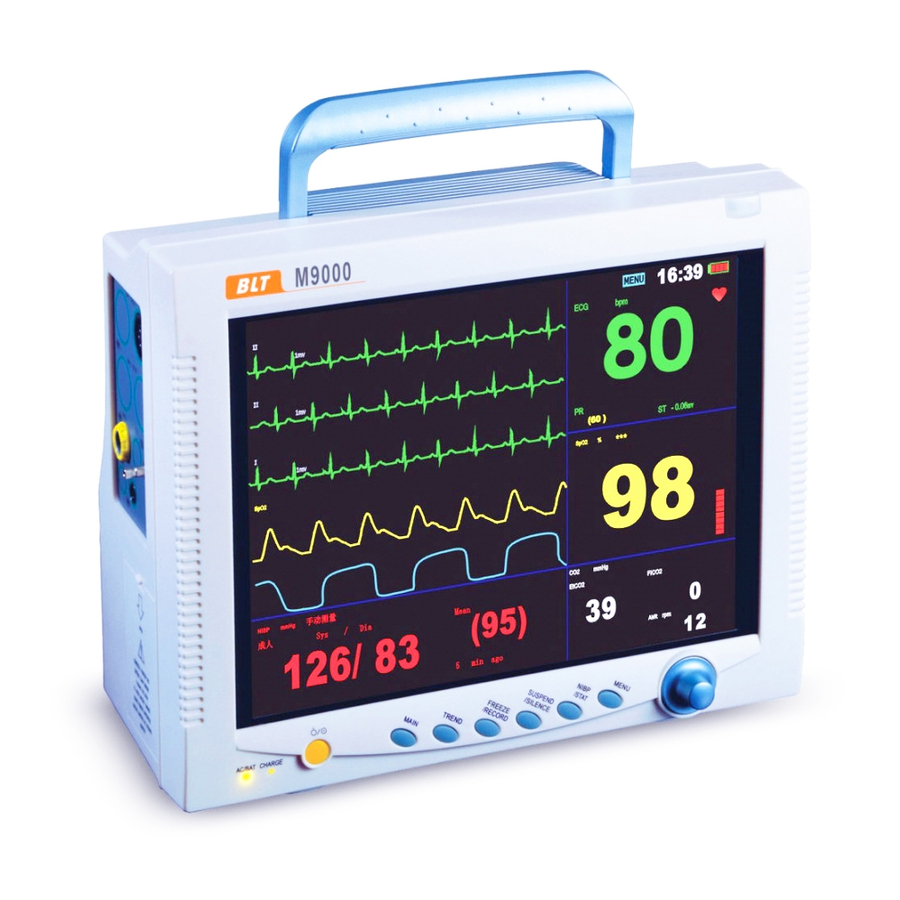
The Basics Monitor Description This monitor integrates the functions of parameter measurement, waveform monitoring, freezing, and recording, etc. Its color TFT liquid crystal display is able to show patient parameters and waveforms clearly. The monitor also features compact size, lightweight, easy-to-carry handle and built-in battery, which make it portable, especially in hospital transport. -
Page 27: Contraindications
The Basics 2.1.2 Contraindications None. 2.1.3 Components This monitor consists of parameter measuring modules, blood pressure cuff, ECG, IBP and CO cables, SpO sensors, CO and AG measuring components. Some of the components are optional and may not apply to your patient monitor. 2.1.4 Functions This monitor is capable of monitoring the following parameters. - Page 28 The Basics End-tidal carbon dioxide (EtCO Fractional inspiratory carbon dioxide (FiCO Air-way Respiration Rate (AwRR) Fraction of inspired carbon dioxide, nitrous oxide, oxygen or anesthetic gas (FiCO , FiN O, FiO , FiAA), and End-tidal carbon dioxide, nitrous oxide or oxygen (EtCO , EtN O, EtO , EtAA)
-
Page 29: External Appearance
The Basics External Appearance 2.2.1 Front Panel Handle Display Control panel Control knob Alarm indicator Figure 2-1 Front Panel This monitor is designed to comply with the requirements of relative international safety standards (IEC60601-1, EN60601-2-27 and EN60601-2-30) for medical electrical equipment. This monitor has floating inputs and is protected against the effects of defibrillation and electrosurgery. -
Page 30: Side Panel
The Basics 2.2.2 Side Panel On the left side of the monitor, you can find the following connectors and the battery compartment. Figure 2-2 Left Side Panel sensor connector (Welch Allyn CO module) Temperature probe connector (channel 1) Temperature probe connector (channel 2) IBP1: IBP transducer connector (channel 1) IBP2:... - Page 31 The Basics On the right side of the monitor, you can find the connector for Oridion or Mindray module or AG module. The recorder is located at the bottom of the right side. (1) (2) Figure 2-3 Right Side Panel...
-
Page 32: Rear Panel
The Basics 2.2.3 Rear Panel Figure 2-4 Rear Panel Fan Vent Speaker holes Mounting holes for support bracket. Network Connector: Standard RJ45 connector. Through network connector, this monitor can be connected with the central monitoring system, another monitor, or a PC. It enables the functions of viewbed monitoring, data output and on-line software upgrading. - Page 33 The Basics Equipotential grounding connector Auxiliary Output Port: A standard BNC connector. It is the common interface of analog output signals, nurse call output signals or defibrillator synchronization signals. You can manually select the function of this port in the USER MAINTAIN menu, please refer to 4.7 Maintenance for details. AC Power Input Connector A three-wire power cord can be connected to this receptacle to provide AC power supply to the patient monitor.
-
Page 34: Control Panel
The Basics Control Panel The control panel as shown below is located at the bottom on the front panel. On the control panel are the following keys and indicator. Figure 2-5 Control Panel Power switch This key turns the monitor ON and OFF. To turn OFF the monitor, please press this key and hold for more than 2 seconds. - Page 35 The Basics NIBP Monitoring for more information. MENU Press this key to display the SYSTEM MENU, as shown in Figure 4-1. Control Knob The main operator control is the control knob. The control knob rotates in either direction to highlight parameter labels and menu options. After highlighting the desired selection, press the control knob to execute an operation, make a selection, view a new menu or a small drop-down list.
-
Page 36: Display
The Basics Display This monitor has a color TFT LCD display of high resolution. It is able to display patient parameters and waveforms clearly. The following is the standard interface when the monitor is operating normally. Figure 2-6 Main Screen Patient information area It displays patient bed number and patient type. - Page 37 The Basics name and sex when no message is to be displayed. Sound icon Alarms Paused ; System Silenced; Alarms Silenced. No icon is displayed under normal status. For more information, see 6.3 Alarm Statuses. Physiological alarms area Physiological alarm messages are displayed in this area. In case of multiple messages, they will be displayed alternately.
- Page 38 The Basics left. You may select a parameter label to open the setup menu of this parameter. Each of the parameter is described in more detail in the following chapters. If you select to turn OFF the alarm of a parameter in its corresponding setup menu, an Alarms Disabled icon will be displayed aside the parameter label.
-
Page 39: Batteries
The Basics Batteries This monitor is designed to operate run battery power when during transport or whenever the power supply is interrupted. The battery is charged automatically when the monitor is connected to AC power, no matter the monitor is powered on or not. -
Page 40: Battery Maintenance
The Basics 2.5.1 Battery Maintenance 2.5.1.1 Conditioning a Battery A battery should be conditioned before it is used for the first time. A battery conditioning cycle is one uninterrupted charge of the battery, followed by an uninterrupted discharge of the battery. Batteries should be conditioned regularly to maintain their useful life. -
Page 41: Battery Recycling
The Basics NOTE Life expectancy of a battery depends on how frequent and how long it is used. For a properly maintained and stored lead-acid or lithium ion battery, its life expectancy is about 2 or 3 years respectively. For more aggressive use models, life expectancy can be less. - Page 42 The Basics FOR YOUR NOTES 2-18...
- Page 43 Installation and Maintenance Installation....................3-2 3.1.1 Unpacking and Checking ..............3-2 3.1.2 Environmental Requirements ............3-3 3.1.3 Power Source Requirements ............3-3 3.1.4 Bracket Mounting................3-3 3.1.5 Installation Method ................. 3-4 3.1.6 Powering on the Monitor..............3-8 3.1.7 Powering off the Monitor ..............3-8 Maintenance ....................
-
Page 44: Installation
WARNING The installation of the monitor must be carried out by personnel authorized by Mindray. The software copyright of the monitor is solely owned by our company. Any action to change, copy or exchange the software copyright by any organization or person is regarded as copyright infringement and is not allowed. -
Page 45: Environmental Requirements
Installation and Maintenance 3.1.2 Environmental Requirements The operating environment of the monitor must meet the requirements specified in the section A.2 Environmental Specifications of Appendix A Product Specifications. The environment where this monitor is to be used should be free from noise, vibration, dust, and corrosive or explosive and inflammable substances. -
Page 46: Installation Method
If the monitor is connected to another electrical instrument and the instrument specifications cannot tell whether the instrument combination is hazardous (e.g. due to summation of leakage currents), you should consult Mindray or experts in the field to ensure the required safety of all instruments concerned. NOTE The following operations are not all required. - Page 47 Installation and Maintenance WARNING Do not use three-wire to two-wire adapter with this instrument. To avoid unexpected power interruption, do no use power outlet with a wall-mounted switch control. 3.1.5.2 Installing the Battery If the monitor is to be powered by the internal battery, install the battery following the steps as below: Slide the battery door toward the rear of the monitor to open it.
- Page 48 Different network cable may be used for different connections. Please consult our customer service personnel for details. The system upgrading through the network connector is to be executed by Mindray authorized personnel only. 3.1.5.6 Auxiliary Output Port The auxiliary output port can be used to generate analog signals, nurse call signals or defibrillator synchronization signals.
- Page 49 Customer Service. The nurse call cable has two non-polarized conducers at the output end. The installation should be performed by Mindray servicing engineers or engineers of the hospital according to the specific nurse call system of the hospital.
-
Page 50: Powering On The Monitor
Installation and Maintenance 3.1.6 Powering on the Monitor After installing the monitor, please follow the procedures described below to power on the monitor: Before using the monitor, please carry out corresponding safety inspection as given in 3.2.1 Inspection. Press the Power Switch on the control panel. A beep will be heard and, at the same time, the alarm indicator will flash once in yellow and then red. -
Page 51: Maintenance
Installation and Maintenance Maintenance WARNING Failure on the part of the responsible hospital or institution employing the use of the monitoring equipment to implement a satisfactory maintenance schedule may cause undue equipment failure and possible health hazard. The safety inspection or maintenance, which requires opening the monitor housing, must be performed by trained and authorize personnel only. -
Page 52: Cleaning
Installation and Maintenance 3.2.2 Cleaning WARNING Be sure to shut down the system and disconnect all power cords from the outlet before cleaning the equipment. Your equipment should be cleaned on a regular basis. If there is heavy pollution or lots of dust and sand in your place, the equipment should be cleaned more frequently. -
Page 53: Disinfection
Installation and Maintenance 3.2.3 Disinfection Disinfection may cause damage to the equipment. We recommend the disinfection is contained in the hospital’s servicing schedule only when necessary. The equipment should be cleaned prior to disinfection. Recommended disinfection material: Alcohol based (Ethanol 70%, Isopropanol 70%), and aldehyde based. - Page 54 Installation and Maintenance FOR YOUR NOTES 3-12...
- Page 55 System Menu Overview..................... 4-2 Patient Setup....................4-4 4.2.1 Admit Patient .................. 4-5 4.2.2 Quick Admit Patient ................ 4-7 4.2.3 Modify Patient................. 4-7 4.2.4 Clear Patient Data................4-8 4.2.5 Discharge Patient................4-8 Default Setup....................4-9 System Setup..................... 4-10 4.4.1 Face Select ..................4-11 4.4.2 Alarm Setup ...................4-11 4.4.3 Time Setup ..................
-
Page 56: Overview
System Menu Overview To open a menu, perform any of the following four operations: Press the MENU key on the control panel. The SYSTEM MENU appears. Select the STANDBY label on the main screen. The CONFIRM TO STANDBY menu appears. Select a parameter label in a parameter window. - Page 57 System Menu Exit key: Exits from the current menu. Some menus do not have the EXIT key. Instead, a YES and a NO key or a CONFIRM and a CANCEL key are provided. You can confirm the operations with these keys. The following introduces the submenus of the SYSTEM MENU.
-
Page 58: Patient Setup
System Menu Patient Setup Select PATIENT SETUP>> in SYSTEM MENU. The following menu appears. Figure 4-2 Patient Setup Menu This menu displays the patient’s information, as well as four buttons located below. If no patient is admitted, only the default settings of PAT TYPE and PACE are displayed. -
Page 59: Admit Patient
System Menu 4.2.1 Admit Patient To admit a new patient, please follow this procedure: Select ADMIT PATIENT in PATIENT SETUP menu. Select YES in the pop-up CONFIRM TO CLEAR THE DATA menu. The menu as shown below appears. Figure 4-3 Patient Information Setup 3. - Page 60 System Menu BIRTH Patient date of birth: year-month-day; HEIGHT Patient height (unit: cm or inch); WEIGHT Patient weight (unit: kg or IB); BLOOD Patient blood type: A, B, O, AB or N (N represents unknown) NOTE If the PAT NO or NAME has not been input, “PATI. INFO. IMCMP” will be displayed in the patient information area.
-
Page 61: Quick Admit Patient
System Menu Press the control knob. Rotate the control knob and select the desired bed number. The bed number increases or decreases by one as the control knob rotates. 4.2.2 Quick Admit Patient Select QUICK ADMIT PATIENT in PATIENT SETUP menu. Select YES in the pop-up CONFIRM TO CLEAR THE DATA menu. -
Page 62: Clear Patient Data
System Menu 4.2.4 Clear Patient Data If no patient is admitted, data stored in the patient monitor should be cleared. 1. Click the CLEAR PATIENT DATA button in the PATIENT SETUP menu. 2. Select YES in the pop-up menu. 4.2.5 Discharge Patient If a patient has been admitted, the patient should be discharged. -
Page 63: Default Setup
System Menu Default Setup Select DEFAULT>> in SYSTEM MENU. The following menu appears. Figure 4-5 Default Setup Restoring Factory Default Configuration Rotate the control knob and select the desired configuration. Select EXIT, and a CONFIRM DEFAULT CONFIG dialog box pops up. Select YES to restore the monitor to the selected default configuration, or select NO to cancel the operation. -
Page 64: System Setup
System Menu System Setup Select SYSTEM SETUP>> in SYSTEM MENU. The following menu appears. Figure 4-6 System Setup SYSTEM SETUP menu contains the following submenus: FACE SELECT>> ALARM SETUP>> TIME SETUP>> RECORD>> DATA OUTPUT>> ANALOG>> MODULE SETUP>> TRACE SETUP>> MARK EVENT>> 4-10... -
Page 65: Face Select
System Menu 4.4.1 Face Select Select FACE SELECT>> in SYSTEM SETUP menu. The following menu appears. Figure 4-7 Face Select In the FACE SELECT menu, options are available as shown above. For detailed information, see 5 Face Selection. 4.4.2 Alarm Setup Select ALARM SETUP>>... - Page 66 System Menu ALM SEL Alarm selection Options: COMMON ALM SETUP, XX ALM SETUP; (XX refers to HR, ST, PVCs, SPO2, NIBP, IBP (1,2), CO2, RESP, TEMP, CO and AG). ALARM VOL Alarm volume The volume can be set between 0 and 10. 0 means off and 10 is the maximum volume.
-
Page 67: Time Setup
System Menu 4.4.3 Time Setup Select TIME SETUP>> in SYSTEM SETUP menu. The following menu appears. Figure 4-9 Time Setup With the control knob, you can change the year, month, day, hour, minute and second as well as select the displayed format of the time. YYYY, MM, and DD refer to year, month and day respectively. -
Page 68: Recorder Setup
System Menu 4.4.4 Recorder Setup Select RECORD>> in SYSTEM SETUP menu. The following menu appears. Figure 4-10 Recorder Setup REC WAVE1 Recorded waveform1 Options: ECG1, ECG2, SPO2, IBP1, IBP2, CO2, RESP, N2O, O2, AA and OFF. In MULTI-LEADS DISPLAY mode or HALF-SCREEN MULTI-LEADS display mode, the ECG3, ECG4, ECG5 and ECG6 options are also available. - Page 69 System Menu RT REC TIME Real-time recording time Options: CONTINUAL and 8s. TIMING REC Timing recording time TIME The interval between automatic recordings. Options: OFF, 10MIN, 20MIN, 30MIN, 40MIN, 50MIN, 1HOUR, 2HOURS, 3HOURS and 4HOURS. The monitor will start recording at the selected interval, record for 8s and stop automatically.
-
Page 70: Data Output
System Menu 4.4.5 Data Output Select DATA OUTPUT>> in SYSTEM SETUP menu. The following menu appears. Figure 4-11 Data Output Output Procedure Disconnect all patient cables connected to the monitor. Verify the monitor is connected to the PC and the PC is running the Patient Information Recall System software. -
Page 71: Analog Output
System Menu 4.4.6 Analog Output Select ANALOG >> in SYSTEM SETUP menu. The following menu appears. Figure 4-12 Analog Output You can perform the following settings in the menu above: ANALOG OUT Analog output Options: ON and OFF. When ON is selected, analog signals can be output from the auxiliary output port on the rear panel of the monitor. -
Page 72: Module Setup
System Menu 4.4.7 Module Setup Select MODULE SETUP>> in SYSTEM SETUP menu. The following menu appears. Figure 4-13 Module Setup This menu allows you to enable or disable a parameter module to determine the information displayed on the main screen. As shown in the figure above, “√” indicates an enabled module. -
Page 73: Trace Setup
System Menu 4.4.8 Trace Setup Select TRACE SETUP>> in SYSTEM SETUP menu. The following menu appears. Figure 4-14 Trace Setup This menu allows you to select the parameter waveform(s) to be displayed. The mark “√” indicates the parameter waveform will be displayed, and that without the mark will not be displayed. -
Page 74: Mark Event
System Menu 4.4.9 Mark Event Select MARK EVENT>> in SYSTEM SETUP menu. The following menu appears. Figure 4-16 Mark Event This menu allows you to mark four different events, namely event A, B, C and D. The ”@” symbol will appear in the frame of the even being selected. If you attempt to unmark an event, press the control knob again on the marked selection. -
Page 75: Selection Setup
System Menu Selection Setup Select SELECTION>> in SYSTEM MENU. The following menu appears. Figure 4-17 Selection Setup You can perform the following settings in this menu: KEY VOL Key volume The volume can be set between 0 and 10. 0 indicates the volume is off and 10 indicates the maximum volume. -
Page 76: Monitor Version
System Menu Monitor Version Select VERSION>> in SYSTEM MENU. The following menu appears. Figure 4-18 Version You can see the software versions of the monitor. The DEVICE CONFIG LIST>> option allows you to see the configuration of the monitor. Figure 4-19 Device Configuration List 4-22... - Page 77 System Menu The DEVICE VERSION LIST>> option allows you to see the following version information. Figure 4-20 Device Version List 4-23...
-
Page 78: Maintenance
System Menu Maintenance Select MAINTAIN>> in SYSTEM MENU. The following menu appears. Figure 4-21 Enter Maintain Password Enter USER KEY, then select CONFIRM button. The following menu appears. Figure 4-22 User Maintain You can perform the following settings: 4-24... - Page 79 System Menu MONI NAME Monitor’s name. DEPT. The department where the monitor is located. BED NO The bed number where the monitor is located. ALARM ENABLE: the alarm volume can be set to 0; SOUND OFF DISABLE: the alarm volume cannot be set to 0.. The audible alarms will be turned ON when the monitor is restarted.
- Page 80 System Menu NURSE CALL If this option is selected, the auxiliary output port will be able to output nurse call signals, and you can perform the settings in the NURSE CALL SETUP submenu of the USER MAINTAIN menu. For details, see 4.7.4 Nurse Call Setup.
-
Page 81: Ip Address Setup
System Menu 4.7.1 IP Address Setup When the monitor is connected with the central monitoring system, and the NET TYPE is CMS+, you need to set the IP address of your monitor. Select IP ADDRESS SETUP in USER MAINTAIN menu. The following menu appears. For details, please contact with the technician responsible for the central monitoring system in your hospital. -
Page 82: Self Definition Of Color
System Menu Figure 4-24 Wireless Net Setup 4.7.3 Self Definition of Color Select COLOR SELF-DEFINE >> in USER MAINTAIN menu. The following menu appears. Figure 4-25 Self-definition of color This menu allows you to choose in which color the waveform(s) and parameter(s) of a parameter module are to be displayed. -
Page 83: Nurse Call Setup
System Menu 4.7.4 Nurse Call Setup Select NURSE CALL SETUP >> in USER MAINTAIN menu. The following menu appears. Figure 4-26 Nurse Call Setup You can perform the following settings: SIGNAL DURATION Two options are available: PULSE, and CONTINUUM. PULSE When pulse is selected, a nurse call signal is a pulse signal lasting 1s. - Page 84 System Menu ALM LEV Alarm level Options: HIGH, MED (medium) and LOW. More than one option can be selected at one time. ALM TYPE Alarm type Options: TECH. (technical) and PHYS. (physiological). Both options can be selected at one time. Trigger Conditions A nurse call signal will be triggered only if all the following conditions are met: The nurse call function is enabled.
-
Page 85: Co User Maintain
System Menu 4.7.5 User Maintain Selecting CO2 USER MAINTAIN >> in USER MAINTAIN menu opens the CO2 USER MAINTAIN menu. The options contained in this menu are relative with the module that you monitor is equipped with. For details, please refer to 17.2.4 CO2 User Maintain Menu and 17.3.4 CO2 User Maintain Menu. -
Page 86: Demo Function
System Menu DEMO Function Select DEMO >> in SYSTEM MENU. The following menu appears. Figure 4-28 Input Demo Key The monitor enters the demonstration mode when the correct password is input in the menu above. The word DEMO will be displayed on the main screen. The purpose of the demonstration display is to demonstrate the performance of the monitor, and for training purposes. - Page 87 Face Selection Standard Screen................... 5-2 Trend Screen ....................5-3 OxyCRG Screen..................5-4 Viewbed Screen................... 5-5 Large Font Screen ..................5-7 Standby Mode ..................... 5-8...
-
Page 88: Standard Screen
Face Selection Standard Screen As described in 4.4.1 Face Select, you can open the FACE SELECT menu by selecting FACE SELECT >> in SYSTEM SETUP menu. Figure 5-1 Face Select The standard screen is the default screen. If the current screen is not the standard screen, you may enter the standard screen by selecting STANDARD SCREEN and then selecting EXIT in FACE SELECT menu. -
Page 89: Trend Screen
Face Selection Trend Screen To enter the following screen, select TREND SCREEN in FACE SELECT menu and then select EXIT. Figure 5-3 Trend Screen Trend graph Trend graphs locate to the right of the corresponding waveform in the waveform area, and display the trends of one parameter of each module. The parameter labels, as well as their scales, are displayed to the left of the trend graph. -
Page 90: Oxycrg Screen
Face Selection OxyCRG Screen To enter the following screen, select oxyCRG SCREEN in FACE SELECT menu and then select EXIT. Figure 5-4 OxyCRG Screen Oxy CRG screen is located at the lower part of the waveform area, consisting of the HR trend, the SpO trend, and the RR (respiration rate) trend or the compressed respiration waveform. -
Page 91: Viewbed Screen
Face Selection Viewbed Screen This monitor can view one parameter waveform and measured data from another patient monitor (viewbed monitor) on the same monitoring network. To enter the following screen, open FACE SELECT menu, select VIEWBED SCREEN, and then select EXIT. Figure 5-5 Viewbed Screen The monitor you are viewing from is called “host monitor”. - Page 92 Face Selection of the following parts. Viewbed monitor label The viewbed monitor lable allows you to select the viewbed monitor you want to view. It displays the bed number and patient name of the viewbed monitor. If they are not entered, the label displays blank. If the host monitor is not connected with any other monitor on the same network, the label displays N/A.
-
Page 93: Large Font Screen
Face Selection Large Font Screen To enter the following screen, open FACE SELECT menu, select LARGE FONT SCREEN, and then select EXIT. Figure 5-6 Large Font Screen As shown above, the HR, SpO and NIBP values (diastolic pressure, mean pressure and systolic pressure) are displayed in large font. -
Page 94: Standby Mode
Face Selection Standby Mode During patient transport or temporary departure of a patient, the monitor can be set to STANDBY mode. In this mode, the monitor suspends the monitoring and measurement on the patient and shields all alarm indications. Besides the WORK MODE of CO and AG module, which will also be changed to STANDBY, the previous menu settings and patient information keep unchanged. - Page 95 Alarms Overview..................... 6-2 6.1.1 Alarm Categories................6-2 6.1.2 Alarm Levels................... 6-3 Alarm Modes....................6-4 6.2.1 Visual Alarms .................. 6-4 6.2.2 Audible alarms ................6-4 6.2.3 Alarm Messages ................6-5 6.2.4 Parameter Flashes................6-5 Alarm Statuses .................... 6-6 6.3.1 Alarms Disabled................6-6 6.3.2 Alarms Paused.................
-
Page 96: Overview
Alarms Overview The monitor gives audible or visual alarms to indicate the medical staff, when a vital sign of the patient appears abnormal, or mechanical or electrical problems occur to the monitor. Upon turning on the monitor, a beep will be heard. At the same time, the alarm indicator will flash once in yellow and red. -
Page 97: Alarm Levels
Alarms example, the monitor prompts ”NIBP alarm disabled ! ” at the time the monitor is powered on. Besides, if a parameter module is turned on but the required leads or sensor are not connected, the monitor will prompt accordingly, such as ”ECG LEAD OFF”... -
Page 98: Alarm Modes
Alarms Alarm Modes When an alarm occurs, the monitor raise the user’s attention by the following audible or visual indications. Visual alarms Audible alarms Alarm messages Parameter flashes Besides, the visual alarms, audible alarms and alarm messages are given in different ways to identify different alarm levels. -
Page 99: Alarm Messages
Alarms NOTE When multiple alarms of different levels occur simultaneously, the monitor selects the alarm of the highest level and gives alarm tone accordingly. 6.2.3 Alarm Messages Alarm messages are given when alarms occur. The alarm messages are displayed in the physiological alarms area or the technical alarms area in black. -
Page 100: Alarm Statuses
Alarms Alarm Statuses When an alarm occurs, normally the monitor gives indications in the modes mentioned above as per the alarm level. If necessary, you can the set the monitor to the following alarm statuses. Alarms Disabled Alarms Paused System Silenced Alarms Silenced 6.3.1 Alarms Disabled... -
Page 101: Alarms Paused
Alarms 6.3.2 Alarms Paused To pause all alarms of the monitor for 1, 2 or 3 minutes, press the SILENCE key on the control panel once (for less than 2 seconds). In Alarms Paused status, Visual alarms and audible alarms are both paused. The parameters generating physiological alarms and their upper or lower limits stop flashing. -
Page 102: Status Switchover
Alarms 6.3.5 Status Switchover In the Normal status, Press the SILENCE key for less than 2 seconds to switch to the Alarms Paused status, or Press the SILENCE key for 2 seconds or more to switch to the System Silenced status. -
Page 103: Latching Alarms
Alarms Latching Alarms As described in 4.4.2 Alarm Setup, the parameter alarm type can be set to either LATCH or UNLATCH. If the parameter alarm type is set to LATCH, before or during the occurence of a parameter alarm, the alarm message will be latched even if the initial alarm condition has ceased. -
Page 104: Clearing Alarms
Alarms Clearing Alarms Generally the alarm indications of an alarm will automatically be cleared when the alarm condition that triggered the alarm ceases. However, you can also clear the alarm indications or the latched alarms by the following ways. Clearing audible and visual alarm indications For some technical alarms, the audible and visual alarm indications will be cleared if the monitor is set to the Alarms Paused status (by pressing the SILENCE key for less than 2 seconds), and the alarm message will be changed to prompt information... -
Page 105: When An Alarm Occurs
Alarms When an Alarm Occurs WARNING When an alarm occurs, always check the patient’s condition first. When an alarm occurs to the monitor, refer to the following steps and take action properly. Check the patient’s condition. Identify the alarming parameter and the alarm category. Identify the cause of the alarm. - Page 106 Alarms FOR YOUR NOTES 6-12...
- Page 107 Freezing Waveforms Overview..................... 7-2 Freezing and Unfreezing ................7-2 FROZEN Menu................... 7-3 Waveform Recall..................7-4 Recording Frozen Waveforms..............7-4...
-
Page 108: Overview
Freezing Waveforms Overview You can freeze the monitored waveforms of a patient as desired and view the waveforms of 40 seconds to gain a clear observation. Besides, the monitor can print two frozen waveforms using the recorder. The freezing function of the monitor has the following features. When the monitor enters the frozen mode, it exits all other menus automatically. -
Page 109: Frozen Menu
Freezing Waveforms Press the FREEZE key on the control panel again. After exiting the frozen mode, all waveforms on the screen are cleared and new real-time waveforms are displayed. If the scan type of the monitor is set to REFRESH, the waveforms are refreshed from the left of the waveforms area to the right ;... -
Page 110: Waveform Recall
Freezing Waveforms Waveform Recall In the frozen mode, select the RECALL option in the FROZEN menu, and the option name changes to L-RIGHT. Rotate the control knob clockwise, and the frozen waveforms move to the right. At the lower right corner of the lowest waveform is an arrow pointing upward. The time is indicated below the arrow. - Page 111 Recording Overview..................... 8-2 Recording Types..................8-2 Recorder Operations..................8-5 Installing Recorder Paper ................8-9...
-
Page 112: Overview
Recording Overview A thermal recorder can be equipped with the monitor. The performance of the recorder is described as below. Records patient information and parameters. Records a maximum of two waveforms. The optional recording rates: 25mm/s and 50mm/s. The recording grid is optional. Multiple recording types are supported. - Page 113 Recording menu. You can also select the two waveforms (REC WAVE 1 and REC WAVE 2) to be recorded. If one of the two waveforms is set to OFF, the recorder will merely print out one waveform and all the measured parameters; if both are set to OFF, the recorder will only print all the measured parameter.
- Page 114 Recording Trend graph/table recording When the trend graph/trend table or a recall window is opened, you can select the REC option to print out the trend graph, trend table, NIBP measurement, alarm event or arrhythmia event. CO measurement curve recording When the WINDOW FOR CO MEASUREMENT is opened, you can select the REC option to print the CO measurement curve after measurement.
-
Page 115: Recorder Operations
Recording Recorder Operations Continuous real-time recording Press the RECORD key to start recording. Press the RECORD key again to stop the recording. 8-second real-time recording Press the RECORD key to start recording. The recording stops automatically in 8 seconds. Automatic recording The recorder starts recording automatically at the preset interval (RT REC TIME). - Page 116 Recording Trend graph recording Select TREND GRAPH>> in SYSTEM MENU to open the TREND GRAPH window. Select the REC option to start recording. When the recording completes, the recorder stops automatically. Trend table recording Select TREND TABLE>> in SYSTEM MENU to open the TREND TABLE window.
- Page 117 Recording Arrhythmia alarm recording Select the ECG label in the ECG parameter window to the ECG SETUP menu pops up. Select the ARR ANALYSIS >> option in the ECG SETUP menu, and a popup menu is opened. Select ARR RECALL>> to open the ARR RECALL window. Select the WAVE >>...
- Page 118 Recording OxyCRG recording Enter the OxyCRG screen. Select the RECORD key when the OxyCRG screen is displayed, and the recorder starts recording. When the recording completes, the recorder stops automatically. Monitor status information recording Select MAINTAIN >> in SYSTEM MENU, and a popup menu is opened. Select STATUS >>...
-
Page 119: Installing Recorder Paper
Recording Installing Recorder Paper Installing Procedure Press the latch at the upper right of the paper compartment door to releases the door. Lift the roller lever located at the upper left of the paper compartment as shown in the following figure. Insert a new roll of recorder paper into the compartment as shown below. - Page 120 Recording Removing the Paper Jam If the recorder does not function properly or produces unusual sound, open the recorder door to check for a paper jam. You can follow the operations below to remove the paper jam. Open the recorder door. Tear the paper off from the leading edge at the paper outlet.
- Page 121 Recall Overview..................... 9-2 Trend Graph Recall ..................9-3 Trend Table Recall ..................9-5 NIBP Recall....................9-7 Alarm Event Recall ..................9-8 Non-Volatile Data Storage................. 9-10...
-
Page 122: Overview
Recall Overview The monitor is able to store important patient data so that the user can review and record the data as desired. Trend Graph Recall You can review the latest 1-hour trend graph of a measured parameter displayed every 1 or 5 seconds, or the latest 96-hour trend graph displayed every 1, 5 or 10 minutes. -
Page 123: Trend Graph Recall
Recall Trend Graph Recall Select TREND GRAPH >> in SYSTEM MENU. The following window appears. Trend cursor Cursor time Trend graph Y-axis X-axis Parameters area Figure 9-1 Trend Graph As shown above, PARA SELECT allows you to select a parameter from the options. The trend graph of the selected parameter is displayed. - Page 124 Recall Rotate the control knob and highlight your desired parameter, and then select it. The trend graph of the selected parameter is displayed in the TREND GRAPH window. RESOLUTION Rotate the control knob and highlight the field at the right of RESOLUTION. Press the control knob, and a menu pops up.
-
Page 125: Trend Table Recall
Recall Trend Table Recall Select TREND TABLE >> in SYSTEM MENU. The following window appears. Figure 9-2 Trend Table The TIME is displayed on the left of the trend table. On the top is the latest time. From the upper to the lower, the interval between two adjacent times depends on the preset resolution. - Page 126 Recall RESOLUTION Rotate the control knob to highlight the field at the right of RESOLUTION. Press the control knob, and a popup value with the options, 1MIN, 5 MIN, 10MIN, 30MIN and 60MIN, is opened. The time displayed in the TIME filed changes with the resolution. UP-DOWN Rotate the control knob to highlight the UP-DOWN option, and press.
-
Page 127: Nibp Recall
Recall NIBP Recall Select NIBP RECALL >> in SYSTEM MENU. The following window appears. Figure 9-3 NIBP Recall The NIBP RECALL window shows the non-invasive systolic pressure (NS), non-invasive mean pressure (NM), non-invasive diastolic pressure (ND), puse rate (PR) and the measurement time (TIME). The optional pressure units (UNIT) are mmHg and kPa. -
Page 128: Alarm Event Recall
Recall Alarm Event Recall Select ALARM RECALL >> in SYSTEM MENU. The following menu appears. Figure 9-4 Alarm Recall Condition Selections In this menu, you may select the conditions of alarm review: ALARM RECALL TIME You can select the desired start time and end time for review. The end time can be set to either CURRENT TIME or SELF-DEFINE. - Page 129 Recall The alarm event number (format: NO: n of N). N indicates the amount of alarm events and n indicates the sequence number of the currently displayed alarm event. Parameter values at the time of the alarm event. Two waveforms at the time of the alarm event. You can set the waveform length by selecting from the ALM REC TIME options in the ALARM SETUP menu.
-
Page 130: Non-Volatile Data Storage
Recall Non-Volatile Data Storage To avoid losing patient’s data when the monitor is powered off intentionally or accidentally, this monitor can be equipped with a CF storage card (optional) to realize the non-volatile data storage function. During monitoring, the patient’s data, including trend data, NIBP measurement results, alarm events, arrhythmia events, and relative waveforms, will be saved into the CF storage card. - Page 131 Drug Calculation 10.1 Drug Calculation ..................10-2 10.2 Titration Table ................... 10-5 10-1...
- Page 132 Drug Calculation 10.1 Drug Calculation Select DRUG CALC >> in SYSTEM MENU. The following window appears. Figure 10-1 Drug Calculation 10.1.1.1 Calculation Formula CONCENTRAT = AMOUNT/VOLUME INF RATE = DOSE/CONCENTRAT DURATION = AMOUNT/DOSE DOSE = INF RATE×CONCENTRAT 10.1.1.2 Operating Method Select the drug name Open the drop-down menu of DRUG NAME and select one from the following 15 options:...
- Page 133 Drug Calculation DOPAMINE EPINEPHRINE HEPARIN ISUPREL LIDOCAINE NIPRIDE NITROGLYCERIN PITOCIN NOTE The DRUG names A, B, C, D and E are user-definable. Input the patient weight Select the field on the right of WEIGHT and rotate the control knob to enter the patient weight correctly.
- Page 134 Drug Calculation NOTE In neonate mode, DRIP RATE and DROP SIZE are disabled. The prerequisite for drug calculation is that the drug name and the patient weight are selected. The function of drug calculation is independent from other functions of the monitor.
- Page 135 Drug Calculation 10.2 Titration Table After the drug calculation, select TITRATION in DRUG CALC window. The following window pops up. Figure 10-2 Titration Table BASIC Rotate the control knob to highlight the field on the right of BASIC. Press and rotate the control knob to select DOSE, INF RATE or DRIP RATE. The data in the trend table changes accordingly.
- Page 136 Drug Calculation DOSE TYPE Rotate the control knob to highlight the field on the right of DOSE TYPE. Press and rotate the control knob to select either DOSE/min, DOSE/hr, DOSE/kg/min or DOSE/kg/hr in the popup menu. The data in the trend table changes accordingly. UP-DOWN Rotate the control knob to highlight the UP-DOWN option in the window.
- Page 137 ECG/RESP Monitoring 11.1 Overview....................11-2 11.1.1 ECG Waveform ................11-2 11.1.2 ECG Parameters ................11-4 11.2 ECG Monitoring Procedure ...............11-5 11.2.1 Preparation ..................11-5 11.2.2 Electrode Placement...............11-6 11.3 ECG Setup Menu ..................11-12 11.4 ST Analysis ....................11-21 11.4.1 Overview ..................11-21 11.4.2 ST Analysis Menu ................11-21 11.5 Arrhythmia Analysis ................11-25 11.5.1 Overview ..................11-25 11.5.2 Arrhythmia Analysis Menu ............11-26...
-
Page 138: Overview
ECG/RESP Monitoring 11.1 Overview 11.1.1 ECG Waveform In the standard screen, one or two ECG waveform(s) is (are) displayed at the top of the display when LEAD TYPE is set to 3 LEADS or 5LEADS respectively in the ECG SETUP menu. Figure 11-1 ECG Waveforms As shown above, when 5 LEADS is selected, five labels are located above the ECG waveforms:... - Page 139 ECG/RESP Monitoring DIAGNOSTIC: The monitor displays the ECG waveforms without filter; MONITOR: It effectively filters the artifacts that might cause false alarms; SURGERY: This filter is used to reduce the artifacts and interference from electrosurgery equipment. The selected filter is applied to both channels, but the filter label is merely displayed above the first ECG waveform.
-
Page 140: Ecg Parameters
ECG/RESP Monitoring 11.1.2 ECG Parameters Heartbeat icon ECG label Heart rate value Alarms Disabled icon Figure 11-2 ECG Parameters The parameters related to ECG are displayed to the right of the ECG waveforms as shown above. The heartbeat indicator flashes in the same rate with the patient’s heartbeat. -
Page 141: Ecg Monitoring Procedure
ECG/RESP Monitoring 11.2 ECG Monitoring Procedure 11.2.1 Preparation Skin preparation The quality of ECG information displayed on the monitor is a direct result of the quality of the electrical signal received at the electrode. Proper skin preparation is necessary for good signal quality at the electrode. A good signal at the electrode provides the monitor with valid information for processing the ECG data. -
Page 142: Electrode Placement
ECG/RESP Monitoring 11.2.2 Electrode Placement WARNING Use only the specified ECG cable for monitoring. When applying electrodes or connecting cables, make sure they are not connected to any conductive part or the ground. Verify that all ECG electrodes, including neutral electrodes, are securely attached to the patient. - Page 143 ECG/RESP Monitoring 11.2.2.1 5-Leadwire Electrode Placement Following is the configuration per American standard when using five leadwires: Figure 11-3 5-Leadwire Electrode Placement RA (right arm) electrode: near the right shoulder, directly below the clavicle. LA (left arm) electrode: near the left shoulder, directly below the clavicle. RL (right leg) electrode: on the right hypogastrium.
- Page 144 ECG/RESP Monitoring On the 5th intercostal space at the left posterior axillary line of the back. V7R: On the 5th intercostal space at the right posterior axillary line of the back. Figure 11-4 Positions of Chest Electrode The chart below shows the label used to identify each leadwire. Included also is its associated color code per American (AHA) and European (IEC) standards.
- Page 145 ECG/RESP Monitoring 11.2.2.2 3-Leadwire Electrode Placement Following is the configuration per European standard when using three leadwires: R (right arm) electrode: near the right shoulder, directly below the clavicle. L (left arm) electrode: near the left shoulder, directly below the clavicle. F (left leg) electrode: on the left hypogastrium.
- Page 146 ECG/RESP Monitoring 11.2.2.3 Electrode Placement for Surgical Patients Electrode placement during surgery is dependent on the type of surgery being performed. For example, with open chest surgery, the electrodes might be placed laterally on the chest or on the back. In the operating room, artifact can sometimes affect the ECG waveform due to the use of electrosurgery equipment.
- Page 147 ECG/RESP Monitoring 11.2.2.4 Characteristics of Quality ECG Signal As shown in Figure 11-6, the normal QRS complex should exhibit the following characteristics. Tall and narrow with no notches. With a tall R-wave completely above or below the baseline. With a pacer spike no higher than the height of the R-wave. With the T-wave less than one-third of the height of the R-wave.
-
Page 148: Ecg Setup Menu
ECG/RESP Monitoring 11.3 ECG Setup Menu Select the ECG label in the parameter windows. The following menu appears. Figure 11-7 ECG SETUP Menu In this menu, you can perform the following settings: HR ALM Heart rate alarm on/off status ON: When a heart rate alarm occurs, the monitor gives alarm indications and stores the alarm;... - Page 149 ECG/RESP Monitoring For different patient types, the upper/lower limits of the heart rate alarm may vary in the following range. Patient type Max. ALM HI Min. ALM LO Increment (beat/min) Adult Pediatric Neonate NOTE Always set the alarm limits according to the clinical condition of the individual patient.
- Page 150 ECG/RESP Monitoring NOTE If SPO2 is selected from the HR FROM options, the volume of PITCH TONE will be determined by the PR SOUND setting in the SPO2 SETUP menu. If other HR FROM option is selected, the volume of PITCH TONE will be determined by the BEAT VOL (beat volume) setting.
- Page 151 ECG/RESP Monitoring ECG DISPLAY ECG display mode Three options are available: NORMAL DISPLAY: The monitor displays two ECG waveforms when the 5-lead set is used or one ECG waveform when the 3-lead set is used. MULTI-LEADS DISPLAY: The monitor displays six ECG waveforms, which occupies the whole waveforms area.
- Page 152 ECG/RESP Monitoring NOTE The SMART LEAD OFF function is available only when the LEAD TYPE is 5 LEADS and 12 LEADS. When the HR CHANNEL is set to AUTO, SMART LEAD OFF does not work as long as there is ECG waveform displayed in either channel 1 or When you perform ECG calibration, SMART LEAD OFF does not work.
- Page 153 ECG/RESP Monitoring NOTE When monitoring a patient with a pacemaker, PACE must be turned ON. Otherwise, the system will count the pacemaker pulse as QRS complex. Do not completely depend on the alarms of heart rate. The patient with a pacemaker must be nearly monitored.
- Page 154 ECG/RESP Monitoring NOTE If the filter method of the ECG waveform is set to a non-diagnostic mode, only the NOTCH option ON is active and the monitor filters the signals of the power line frequency; if the filter method is set to the diagnostic mode, two NOTCH options, both ON and OFF, are active, and the system sets the NOTCH to OFF automatically.
- Page 155 ECG/RESP Monitoring WARNING Improper defibrillation will endanger the patient’s safety. You user should decide whether to defibrillate the patient based on the patient’s actual condition. Before defibrillating the patient, the user should ensure the defibrillator and the monitor have been tested as a system and the two devices can work together safely and effectively.
- Page 156 ECG/RESP Monitoring DEFAULT You can use this option to access the ECG DEFAULT CONFIG menu. You may choose the FACTORY DEFAULT CONFIG or the USER DEFAULT CONFIG. After finishing the selection, a dialog pops up asking for confirmation of your selection. 11-20...
-
Page 157: St Analysis
ECG/RESP Monitoring 11.4 ST Analysis 11.4.1 Overview The function of ST analysis is optional. The ST analysis of the monitor is disabled by default. When turning ST ANALYSIS on, the monitor selects DIAGNOSTIC mode automatically. You can set the monitor to MONITOR or SURGERY mode as required. - Page 158 ECG/RESP Monitoring In this menu, you can perform the following settings: ST ANAL ST analysis ON: Enables the ST analysis; OFF: Disables the ST analysis. NOTE When turning ST ANALYSIS on, the monitor selects DIAGNOSTIC mode automatically. You can set the monitor to MONITOR or SURGERY mode as required.
- Page 159 ECG/RESP Monitoring ST Measurement Point Selecting DEF POINT >> opens the following window. Figure 11-11 ST Measurement Point Setting As shown above, the DEF POINT window shows the QRS complex template. Two vertical lines indicate the positions of the ISO and ST points. ISO: It is the base point, used to indicate the baseline point of the ST analysis.
- Page 160 ECG/RESP Monitoring T wave P wave ST measurement Base point ISO ST measurement point value Figure 11-12 ST Measurement Point As shown above, the peak of the R wave is the reference point for ST measurement. The ST measurement value for a beat complex is equal to the vertical difference between the two measurement points.
-
Page 161: Arrhythmia Analysis
ECG/RESP Monitoring 11.5 Arrhythmia Analysis 11.5.1 Overview In clinical application, arrhythmia analysis is used to: Monitor the ECG of neonate or adult patients. Detect the change of heart rate and premature ventricular beat. Store the arrhythmia events and the alarm information generated. The medical professionals can use the arrhythmia analysis to evaluate patients’... -
Page 162: Arrhythmia Analysis Menu
ECG/RESP Monitoring 11.5.2 Arrhythmia Analysis Menu Select ARR ANALYSIS >> in ECG SETUP menu. The following menu appears. Figure 11-13 Arrhythmia Analysis In this menu, you can perform the following settings: ARR ANAL Arrhythmia analysis ON: Enables the arrhythmia analysis; OFF: Disables the arrhythmia analysis. -
Page 163: Arrhythmia Alarm Setup
ECG/RESP Monitoring 11.5.3 Arrhythmia Alarm Setup Select ARR ALARM >> in ECG SETUP menu. The following menu appears. You can change the settings of the arrhythmia alarm in this menu. Figure 11-14 Arrhythmia Alarm Setup In the menu, the ALM field indicates the alarm on/off status, REC indicates the alarm recording on/off status and LEV indicates the alarm level. -
Page 164: Arrhythmia Recall
ECG/RESP Monitoring 11.5.4 Arrhythmia Recall Selecte ARR RECALL >> in ARR ANALYSIS menu. The following menu appears. You can review any stored arrhythmia event in this menu. Figure 11-15 Arrhythmia Recall You can perform the following operations: UP-DOWN A maximum of 10 arrhythmia events can be displayed in the window each time. - Page 165 ECG/RESP Monitoring Figure 11-16 Arrhythmia waveform Review You can perform the following operations: UP-DOWN This option allows you to page up and down to review the waveform and the parameters of other arrhythmia events. L-RIGHT This option allows you to review 8-second waveform of the currently displayed arrhythmia event.
-
Page 166: Ecg 12-Lead Monitoring
ECG/RESP Monitoring 11.6 ECG 12-Lead Monitoring 11.6.1 General ECG Waveform In the 12-lead monitoring process, two channels of waveforms are displayed in the waveform area. See 11.1.1 ECG Waveform. Optional leads for Channel 1 and Channel 2 include: I, II, III, aVR, aVL, aVF and V, among which V refers to the waveform of the V1 lead. -
Page 167: Monitoring Procedure
ECG/RESP Monitoring INF: II, III, aVF and aVR LAT: I, aVL, V5 and V6 Each ST group corresponds to an alarm limit. Once there is a parameter exceeding the alarm limit of the group to which the ST parameter belongs, the alarm will be triggered and the name of the group will flash. - Page 168 ECG/RESP Monitoring V2: On the 4th intercostal space at the left sterna margin; V3: Midway between V2 and V4 electrodes; V4: On the 5th intercostal space at the left clavicular line; V5: On the left anterior axillary line, horizontal with V4 electrode; V6: On the left middle axillary line, horizontal with V4 electrode;...
- Page 169 ECG/RESP Monitoring Connections of leadwires I, II, and III are the standard leads, aVR, aVL and aVF are monopolar augmented limb leads, and Vx (x corresponds to any of 1, 2, 3, 4, 5 and 6.) is the monopolar chest lead. Together, these leadwires structure the 12-lead connection. Figure 11-21 12-lead connection methods 11-33...
-
Page 170: Ecg Setup Menu For 12-Lead Monitoring
ECG/RESP Monitoring 11.6.3 ECG Setup Menu for 12-Lead Monitoring Select the ECG label in the parameter windows. The following menu appears. Figure 11-22 ECG Setup Menu This menu contains ECG setup items and sub-menus. For details, refer to 11.3 ECG Setup Menu. - Page 171 ECG/RESP Monitoring For details about this menu, refer to 11.3 ECG Setup Menu, Other Setup. To conduct the 12-lead ECG monitoring, you can set PACE LEAD as I, II, III, aVR, aVL, V1, V2, V3, V4, V5 and V6. NOTE You can switch the leads by setting LEAD TYPE in the ECG SETUP menu.
- Page 172 ECG/RESP Monitoring Waveform gain label 12-lead analysis labels Rhythm lead label Figure 11-24 ECG 12-lead analysis screen NOTE In the 12-lead analysis mode, the monitor cannot be set to the standby mode and the LEAD TYPE option in the ECG SETUP menu is disabled. In the 12-lead analysis mode, the system will automatically disable the DEFIB.
- Page 173 ECG/RESP Monitoring GAIN Used to adjust the amplitudes of ECG waveforms for all leads. Option: ×0.125, ×0.25, ×0.5, ×1, ×2, AUTO If GAIN is set to AUTO, the gain will be adjusted by the monitor automatically. Each waveform is followed by a 1mV scaling line, the height of which is proportional to the amplitude of the waveform.
- Page 174 ECG/RESP Monitoring You can print the analysis result by selecting the REC button in the ECG 12 LEAD ANALYSIS RESULT. WAVESET>> You can select this label to enter the 12 LEAD WAVE menu, and then select the required waveset. The rhythm lead waveform will always be displayed at the bottom in spite of the set mode.
- Page 175 ECG/RESP Monitoring ST Analysis Select the ST label in the parameter area, or select ST ANALYSIS >> in ECG SETUP menu. The following menu appears. Figure 11-27 ST ANALYSIS menu In the ST ANALYSIS menu, you can perform the following settings: ST ANAL ST analysis ON: Enables the ST analysis;...
- Page 176 ECG/RESP Monitoring ALM REC ST alarm recording ON: The monitor starts recording when an ST alarm occurs; OFF: The monitor does not record when an ST alarm occurs. ANT ALM HI Determines the upper limit of the ST alarm in the ANT group; 2.0mV is the highest.
-
Page 177: Data Review
ECG/RESP Monitoring 11.6.4 Data Review If 12-lead monitoring is performed within the latest reviewable 96hr, you can review the 12-lead trend data in the TRAND GRAPH and TREND TABLE window. Trend graph In SYSTEM MENU, select TREND GRAPH >>. The TREND GRAPH window appears. - Page 178 ECG/RESP Monitoring Figure 11-30 Trend table You can review the ST parameters of the 12-lead monitoring. Through the L-RIGHT button, 3 groups of ST numerics can be displayed. ARR review For details about the ARR review, refer to 11.5.4 Arrhythmia Recall. For the ARR review in the 12-lead monitoring, the ST parameters displayed in the review screen are ST-I, ST-II and ST-V1, and the displayed waveforms are the waveforms of the first two ECG channels.
-
Page 179: Resp Monitoring
ECG/RESP Monitoring 11.7 RESP Monitoring 11.7.1 Overview Respiration is detected by measuring thoracic impedance. The monitor measures the change of the impedanec between the RA and LA electrodes of the ECG lead I, or the RA and LL electrodes of the ECG lead II, and produces a respiration waveform as shown below. -
Page 180: Electrode Placement
ECG/RESP Monitoring 11.7.2 Electrode Placement Since the same electrodes are used for ECG and respiration monitoring, the electrode placement is very important. Some patients, due to their clinical condition, expand their chest laterally, causing a negative intrathoracic pressure. In these cases it is better to place the two electrodes used for respiration monitoring laterally in the right axillary and left lateral chest areas, at the maximum point of the breathing movement, to optimize the respiratory waveform. -
Page 181: Respiration Setup
ECG/RESP Monitoring 11.7.3 Respiration Setup Selecting the RESP label on the screen opens the following menu. Figure 11-33 RESP Setup Menu In this menu, you can perform the following settings. Alarm on/off ON: When a respiration rate alarm occurs, the monitor gives alarm indications and stores the alarm;... - Page 182 ECG/RESP Monitoring For different patient types, the upper/lower limits of the respiration rate alarm may vary in the following range. Increment Patient type Max. ALM HI Min. ALM LO Adult Neonate/pediatric APNEA ALM Apnea alarm Determines whether the patient’s cessation of breath is an apnea event.
-
Page 183: Maintenance And Cleaning
ECG/RESP Monitoring 11.8 Maintenance and Cleaning WARNING Before cleaning the ECG cable, be sure to disconnect the monitor from the ECG cable, or shut down the system and disconnect all power cords from the outlet. If the ECG cable is damaged or aged, replace with a new one. Cleaning The exterior surfaces of the ECG cable may be cleaned with a soft cloth, dampened with the alcohol, and then be air-dried or dried with a clean dry cloth. - Page 184 ECG/RESP Monitoring FOR YOUR NOTES 11-48...
- Page 185 Monitoring 12.1 Overview....................12-2 12.2 Mindray SpO Module ................12-4 12.2.1 Principles of Operation..............12-4 12.2.2 Precautions ..................12-5 12.2.3 Monitoring Procedure ..............12-6 12.2.4 Measurement Limitations.............. 12-8 12.2.5 SpO Setup Menu ................12-9 12.3 Masimo SpO Module................12-12 12.3.1 Principles of Operation..............12-12 12.3.2 Precautions ..................
-
Page 186: Overview
Monitoring 12.1 Overview The monitor measures the patients’ SpO (oxygen saturation) and displays: Pulse rate (PR) value in the ECG or SpO parameter window. PLETH waveform in the waveforms area. Oxygen saturation (SpO %) value in the SpO parameter window. The PR value is displayed in the ECG parameter window only if: is selected from the HR FROM options in the ECG SETUP menu;... -
Page 187: Mindray Spo
If the PR SOUND or BEAT VOL is set to 0, the PITCH TONE function will be muted; if the SpO module is disabled, the PITCH TONE function will be disabled as well. This monitor can be equipped with any of the following SpO modules: Mindray SpO module Masimo SpO module Nellcor SpO module... -
Page 188: Principles Of Operation
12.2 Mindray SpO Module NOTE This section is only applicable to the monitor equipped with a Mindray module. 12.2.1 Principles of Operation monitoring is a non-invasive technique used to measure the amount of oxygenated haemoglobin and pulse rate by measuring the absorption of selected wavelengths of light. -
Page 189: Precautions
Monitoring 12.2.2 Precautions WARNING The SpO value might be overestimated in the presence of Hb-CO, Met-Hb or dye dilution chemicals. Check if the sensor cable is in normal condition before monitoring. Do not use the SpO sensor once the package or the sensor is found damaged. -
Page 190: Monitoring Procedure
Monitoring 12.2.3 Monitoring Procedure Sensor selection for SpO measurement depends on the patient type. For an adult patient, you can choose a finger SpO sensor; for an infant patient, you can choose a hand or toe sensor. Refer to the following procedure. Power on the monitor. - Page 191 Monitoring Figure 12-3 Neonate Sensor Placement (1) Figure 12-4 Neonate Sensor Placement (2) Wind the SpO sensor around a hand or foot of a neonate patient. Hold the sensor, pull the belt and fit one of its sides with “V” edge into the “V” groove on the corresponding side of the sheath.
-
Page 192: Measurement Limitations
Monitoring NOTE If the sensor cannot be positioned accurately to the part to be measured, it may result in inaccurate SpO reading, or the SpO even cannot be measured because no pulse is detected. In this case, you must position the sensor again. -
Page 193: Spo Setup Menu
Monitoring Excessive ambient light; Improper sensor installation or incorrect sensor placement on the patient Sensor temperature (optimal temperature is between 28℃ and 42℃); The sensor is placed on a limb that is attached to a blood pressure cuff, arterial catheter, or intravascular line; Concentration of dysfunctional hemoglobin, such as carboxyhemoglobin and methemoglobin;... - Page 194 Monitoring alarm on/off status ON: When a SpO alarm occurs, the monitor gives alarm indications and stores the alarm; OFF: When a SpO alarm occurs, the monitor neither gives alarm indications nor stores the alarm; When OFF is selected, the icon is displayed on the right of the SPO2 label.
- Page 195 Monitoring WARNING Setting the SpO upper alarm limit to 100% will disable the upper alarm limit. High oxygen levels may predispose a premature infant to retrolental fibroplasia. Therefore, the upper alarm limit for oxygen saturation must be carefully selected in accordance with the commonly accepted clinical practices.
-
Page 196: Masimo Spo Module
Monitoring 12.3 Masimo SpO Module NOTE This section is only applicable to the monitor equipped with a Masimo module. 12.3.1 Principles of Operation The pulse oximetry measurement module (Masimo Set, which is called MS-7 ) is based on three principles: Oxyhemoglobin and deoxyhemoglobin differ in their absorption of red and infrared light (spectrophotometry). - Page 197 Monitoring absorbance signals: This value of R is used to find the SpO in a look-up table built into the instrument’s software. The values in the look-up table are based upon human blood studies against a laboratory co-oximeter on healthy adult volunteers in induced hypoxia studies.
-
Page 198: Precautions
Monitoring Discrete Saturation Transform %SpO The DST plot has two peaks: the peak corresponding to the higher saturation is selected as the SpO value. This entire sequence is repeated once every two seconds on the most recent four seconds of raw data. The SpO value therefore corresponds to a running average of arterial hemoglobin saturation that is updated every two seconds. - Page 199 Monitoring To ensure patient electrical isolation, connect only to other equipment with electronically isolated circuits. Do not connect to an electrical outlet controlled by a wall switch or dimmer. Carefully route patient cabling to reduce the possibility of patient entanglement or strangulation. Interfering Substances: Carboxyhemoglobin may erroneously increase readings.
-
Page 200: Monitoring Procedure
Monitoring 12.3.3 Monitoring Procedure Follow the procedure as below: Power on the monitor. Attach the sensor to the proper site on the patient. Plug the connector of the sensor extension cable into the SpO connector on monitor. The process of SpO plethysmogram measurement is generally the same. -
Page 201: Spo Setup Menu
Monitoring A blood pressure cuff is inflated on the same extremity as the one with a SpO sensor attached; The patient has hypotension, severe vasoconstriction, severe anemia, or hypothermia; There is arterial occlusion proximal to the sensor; The patient is in cardiac arrest or is in shock. 12.3.5 SpO Setup Menu Selecting the SPO... - Page 202 Monitoring ALM REC Alarm recording ON: When a SpO alarm occurs, the monitor enables the recording; OFF: When a SpO alarm occurs, the monitor does not enable the recording. SPO2 ALM HI upper alarm limit SPO2 ALM LO lower alarm limit PR ALM HI PR upper alarm limit PR ALM LO...
-
Page 203: Sensors And Accessories
Monitoring PR SOUND Pulse volume Range: 0–10. 0 indicates the volume is closed and 10 indicates the maximum volume. AVG TIME Average time Determines the average SpO calculation time. Options: 2-4S, 4-6S, 8S, 10S, 12S, 14S and 16S. SENSITIVITY Options: NORMAL and HIGH. MODE NIBP SIMUL ON: When measuring NIBP and SpO... - Page 204 Monitoring 12.3.6.1 Selecting a Masimo sensor When selecting a sensor, consider, the patient’s weight, the adequacy of perfusion, the available sensor sites, and the duration of monitoring. For more information contact Masimo. Use only Masimo sensors and sensor cables. Select an appropriate sensor, apply as directed, and observe all warnings and cautions presented in the directions for use accompanying the sensor.
- Page 205 Monitoring 12.3.6.3 Cleaning and Reusing a Masimo LNOP Sensor Reusable sensors can be cleaned per the following procedure: Remove the sensor from the patient. Disconnect the sensor from the monitor. Wipe the entire sensor with a 70% isopropyl alcohol pad, and clean with a dry cloth.
-
Page 206: Masimo Information
Monitoring 12.3.7 Masimo Information ® The MASIMO SET Product ® Masimo Patents This device is covered under one or more the following U.S. Patents: 5,482,036; 5,490,505; 5,632,272; 5,685,299; 5,758,644; 5,769,785; 6,002,952; 6,036,642; 6,067,462; 6,206,830; 6,157,850 and international equivalents. U.S.A and international patents pending. -
Page 207: Nellcor Spo Module
Monitoring 12.4 Nellcor SpO Module NOTE This section is only applicable to the monitor equipped with a Nellcor module. 12.4.1 Principles of Operation Bone, tissue, pigmentation, and venous vessels normally absorb a constant amount of light over time. The arteriolar bed normally pulsates and absorbs variable amounts of light during the pulsations. - Page 208 Monitoring absorption (i.e., measurements at systole and diastole). By doing so, it focuses on light absorption by pulsatile arterial blood, eliminating the effects of nonpulsatile absorbers such as tissue, bone, and venous blood. Automatic Calibration Because light absorption by hemoglobin is wavelength dependent and because the mean wavelength of LEDs varies, a monitor must know the mean wavelength of the sensor’s red LED to accurately measure SpO .
-
Page 209: Precautions
Monitoring Figure 12-8 Oxyhemoglobin Dissociation Curve 12.4.2 Precautions WARNING Pulse oximeter can overestimate the SpO value in the presence of Hb-CO, Met-Hb or dye dilution chemicals. ES (Electrosurgery) equipment wire and SpO cable must not be tangled up. Carefully route patient cabling to reduce the possibility of patient entanglement or strangulation. -
Page 210: Monitoring Procedure
Monitoring WARNING Do not perform SpO monitoring and NIBP measurements on the same arm simultaneously. Obstruction of blood flow during NIBP measurements may adversely affect the reading of the SpO value. Before performing the testing, check the sensor cable. After unplugging the SpO sensor cable from the socket, the system shall display the prompt information "SPO2 SENSOR OFF"... -
Page 211: Measurement Limitations
Monitoring 12.4.4 Measurement Limitations If the accuracy of any measurement does not seem reasonable, first check the patient’s vital signs by an alternate method. Then check the instrument for proper function. Inaccurate measurements may be caused by: Incorrect sensor application or use; Placement of a sensor on the same extremity with a blood pressure cuff, arterial catheter, or intravascular line;... -
Page 212: Spo Setup Menu
Monitoring If poor perfusion affects performance, consider using the Oxisensor R-15 sensor; it obtains measurements from the nasal septal anterior ethmoid artery, an artery supplied by the internal carotid. This sensor may obtain measurements when peripheral perfusion is relatively poor. For low peripheral perfusion, consider using the Nellcor RS-10 sensor, which is applied to the forehead or temple. - Page 213 Monitoring OFF: When a SpO alarm occurs, the monitor does not enable the recording. SPO2 ALM HI upper alarm limit SPO2 ALM LOW lower alarm limit PR ALM HI PR upper alarm limit PR ALM LO PR lower alarm limit and PR alarm limits: Parameter Max.
-
Page 214: Accessories
Monitoring AVG TIME Average time Determines the average SpO calculation time. Options: 4S, 8S and 16S. NIBP SIMUL ON: When measuring NIBP and SpO at the same side, the alarm status remains unchanged until the NIBP measurement is finished; OFF: The function of NIBP SIMUL is disabled. DEFAULT You can select this option to access the SPO2 DEFAULT CONFIG menu, in which you may select FACTORY... -
Page 215: Nellcor Information
Monitoring 12.4.7 Nellcor Information Nellcor Patents This device is covered under one or more the following U.S. Patents: 4,802,486; 4,869,254; 4,928,692; 4,934,372; 5,078,136; 5,351,685; 5,485,847; 5,533,507; 5,577,500; 5,803,910; 5,853,364; 5,865,736; 6,083,172; 6,463,310; 6,591,123; 6,708,049; Re.35,122 and international equivalents. U.S.A and international patents pending. - Page 216 Monitoring FOR YOUR NOTES 12-32...
- Page 217 NIBP Monitoring 13.1 Overview....................13-2 13.2 Monitoring Procedure ................13-3 13.2.1 Cuff Selection and Placement ............13-3 13.2.2 Operation Guides................13-5 13.3 Measurement Limitations................13-6 13.4 NIBP Setup Menu ..................13-7 13.4.1 Calibration..................13-9 13.4.2 Testing for Air Leakage............... 13-10 13.5 Maintenance and Cleaning ...............13-11 13-1...
-
Page 218: Overview
NIBP Monitoring 13.1 Overview The Non-invasive Blood Pressure (NIBP) module measures blood pressure using the oscillometric method. This monitor can be applied to adult, pediatric, and neonatal patients. Three modes of measurement are available: manual, automatic and continuous. Manual: Pressing the NIBP key on the control panel starts a NIBP measurement. -
Page 219: Monitoring Procedure
NIBP Monitoring 13.2 Monitoring Procedure WARNING You must not perform NIBP measurements on patients with sickle-cell disease or under any condition in which the skin is damaged or expected to be damaged. For a thrombasthemia patient, it is important to determine whether measurement of the blood pressure shall be done automatically. - Page 220 NIBP Monitoring Make sure that the cuff edge falls within the range of the <-> mark. If it does not, use a larger or smaller cuff that will fit better. The limb chosen for taking the measurement should be placed at the same level as the patient's heart.
-
Page 221: Operation Guides
NIBP Monitoring 13.2.2 Operation Guides To start a manual NIBP measurement Access the NIBP SETUP menu and select MANUAL from the INTERVAL option; then, press the NIBP key on the control panel to start a manual NIBP measurement; or During the interval between two auto NIBP measurements, press the NIBP key on the control panel to start a manual NIBP measurement. -
Page 222: Measurement Limitations
NIBP Monitoring 13.3 Measurement Limitations Non-invasive blood pressure measurement uses the oscillometric method of measurement. The monitor detects the regular arterial pressure pulse. In some circumstances when the patient's condition makes it difficult to detect this pulse, the measurement becomes unreliable and the measurement time increases. You should be aware that the following conditions could interfere with the measurement, make the measurement unreliable, prolong the measurement, or even make a measurement impossible. -
Page 223: Nibp Setup Menu
NIBP Monitoring 13.4 NIBP Setup Menu Selecting the NIBP label in the parameter area opens the following menu. Figure 13-2 NIBP Setup Menu You can perform the following settings in this menu. NIBP alarm on/off status ON: When a NIBP alarm occurs, the monitor gives alarm indications and stores the alarm;... - Page 224 NIBP Monitoring SYS ALM LO Determines the lower limit of the systolic pressure. MEAN ALM HI Determines the upper limit of the mean pressure. MEAN ALM LO Determines the lower limit of the mean pressure. DIA ALM HI Determines the upper limit of the diastolic pressure. DIA ALM LO Determines the lower limit of the diastolic pressure.
-
Page 225: Calibration
NIBP Monitoring DEFAULT >> You can select this option to access the NIBP DEFAULT CONFIG menu, in which you may select FACTORY DEFAULT CONFIG or USER DEFAULT CONFIG. After finishing your selection and exiting the menu, the system pops up a dialog box asking for your confirmation. 13.4.1 Calibration If you select the CALIBRATE option, the monitor starts the NIBP calibration and the CALIBRATE option changes to STOP CAL. -
Page 226: Testing For Air Leakage
NIBP Monitoring NOTE The calibration of the NIBP measurement should be performed every two years or performed according to the Hospital Procedure. 13.4.2 Testing for Air Leakage The PNEUMATIC option is used to test air leakage. When the NIBP cuff is connected, select this option to start the NIBP inflation and test whether the air leakage occurs in the airway. -
Page 227: Maintenance And Cleaning
NIBP Monitoring NOTE Set PAT TYPE to ADU in the PATIENT SETUP menu before leakage test. The pneumatic test, other than being specified in the EN 1060-1 standard, is to be used to simply determine whether there are air leaks in the NIBP airway. - Page 228 NIBP Monitoring Figure 13-5 Replacing the Rubber Bladder To replace the rubber bladder in the cuff: Place the bladder on top of the cuff so the rubber tubes line up with the large opening on the long side of the cuff. Roll the bladder lengthwise and insert it into the opening on the long side of the cuff.
- Page 229 TEMP Monitoring 14.1 Overview....................14-2 14.2 Measurement Procedure................14-3 14.3 TEMP Setup Menu..................14-4 14.4 Maintenance and Cleaning ................ 14-6 14-1...
-
Page 230: Overview
TEMP Monitoring 14.1 Overview The monitor is able to use two temperature probes simultaneously, to obtain two temperature values and the difference between them. The measurement values are displayed in the TEMP parameter window as shown below. Figure 14-1 TEMP Parameter Window TEMP label: Selecting this label opens the TEMP SETUP menu. -
Page 231: Measurement Procedure
TEMP Monitoring 14.2 Measurement Procedure To measure the temperature of a patient, If a disposable temperature probe is used, plug the temperature probe cable in the temperature probe connector on the side panel of the monitor, and then connect the temperature probe with the cable; if a reusable temperature probe is used, connect the temperature probe with the temperature probe connector directly. -
Page 232: Temp Setup Menu
TEMP Monitoring 14.3 TEMP Setup Menu Selecting the TEMP label in the parameter window opens the following menu. Figure 14-2 TEMP Setup Menu You can perform the following settings in this menu. Temperature alarm on/off status ON: When a temperature alarm occurs, the monitor gives alarm indications and stores the alarm;... - Page 233 TEMP Monitoring TD ALM HI Determines the upper limit of the temperature difference between channel 1 and channel 2. TEMP UNIT Options: ℃ and ℉ DEFAULT >> You can select this option to access the NIBP DEFAULT CONFIG menu, in which you may select FACTORY DEFAULT CONFIG or USER DEFAULT CONFIG.
-
Page 234: Maintenance And Cleaning
TEMP Monitoring 14.4 Maintenance and Cleaning WARNING Before cleaning the monitor or the probe, make sure the equipment is turned off and disconnected from AC power. Reusable Temperature Probes The temperature probe should not be heated to a temperature over 100℃ (212 ℉). - Page 235 IBP Monitoring 15.1 Overview....................15-2 15.2 Precautions ....................15-3 15.3 Monitoring Procedure ................15-4 15.4 IBP Menu ....................15-5 15.4.1 IBP Setup Menu ................15-5 15.4.2 IBP Pressure Zero Menu ............... 15-8 15.4.3 IBP Pressure Calibration ..............15-11 15.5 Maintenance and Cleaning ..............15-14 15.6 ICP Transducer ICT/B................
-
Page 236: Overview
IBP Monitoring 15.1 Overview The monitor provides two channels to measure the invasive blood pressure (IBP, including diastolic, systolic and mean pressures), and displays two waveforms. Figure 15-1 IBP Waveform CH1 label: select the waveform of channel 1 to be displayed. CH2 label: select the waveform of channel 2 to be displayed. -
Page 237: Precautions
IBP Monitoring 15.2 Precautions WARNING Use only the IBP transducer specified in this operation manual. Disposable IBP transducers or domes should not be reused. Parts and accessories used must meet the safety requirements of the medical electrical equipment standards. The need for the operator to avoid conductive connection to the applied part likely to degrade safety. -
Page 238: Monitoring Procedure
IBP Monitoring 15.3 Monitoring Procedure Plug the pressure cable into the IBP connector on the monitor and power on the monitor. Prepare the pressure line and transducer by flushing the system with normal saline solution. Make sure the tubing and transducer system is free of air bubbles. -
Page 239: Ibp Menu
IBP Monitoring 15.4 IBP Menu Selecting the IBP (1,2) label in the parameter window opens the following menu. Figure 15-4 IBP (1,2) Select Menu 15.4.1 IBP Setup Menu The IBP SETUP in IBP (1,2) SELECT menu allows you to access the following menu. - Page 240 IBP Monitoring OFF: When a IBP alarm occurs, the monitor neither gives alarm indications nor stores the alarm; When OFF is selected, the icon is displayed on the right of the IBP (1,2) label. ALM LEV Alarm level Options: HIGH, MED and LOW. AMP ADJUST Amplitude adjustment This option allows you to adjust the waveform amplitude.
- Page 241 IBP Monitoring IBP alarm limits Pressure Label Max. Upper (mmHg) Min. Lower (mmHg) Step (mmHg) SCALE This option allows you to open the following menu and set ADJUST >> the positions of the high, reference and low scales for the two waveforms.
-
Page 242: Ibp Pressure Zero Menu
IBP Monitoring EXPAND Selecting this option opens the following menu. You can PRESSURE select the pressure to be measured by P1 and P2. Options: SYS, MEAN, DIA (three pressures are all measured); MEAN (only the mean pressure is measured). Figure 15-8 IBP Pressure Setup Menu DEFAULT >>... - Page 243 IBP Monitoring Pressure Transducer Zeroing Procedure Disconnect the transducer from the patient. Pressure transducer 3-way stopcock Pressure transducer interface cable Monitor Figure 15-10 Pressure Transducer Zeroing Adjust the 3-way stopcock to close the channel leading to the patient. The transducer is open to the atmosphere through the stopcock. Select CH1 ZERO or CH2 ZERO in IBP PRESSURE ZERO menu to start zeroing.
- Page 244 IBP Monitoring Prompt Information Related to Zeroing Take channel 1 as an example. The monitor may give the following prompt information after the pressure transducer zeroing has been finished. CH1 SUCCESSFUL ZERO The zeroing procedure is over. The transducer port opening to the atmosphere is to be closed and the port connecting to the patient opened.
-
Page 245: Ibp Pressure Calibration
IBP Monitoring 15.4.3 IBP Pressure Calibration You can select IBP PRESSURE CALIBRATE in IBP (1,2) SELECT menu to open the following menu. Figure 15-11 IBP Pressure Calibration Menu Calibration Procedure Disconnect the pressure transducer from the patient. Connect the 3-way stopcock, the sphygmomanometer and the inflation orb, using a T-shape connector, as shown below. - Page 246 IBP Monitoring Perform the pressure transducer zeroing beforehand. If the zeroing succeeds, open the stopcock to the sphygmomanometer. In the IBP PRESSURE CALIBRATE menu, select a value from the CH1 CAL VALUE or the CH2 CAL VALUE popup menu. The calibration pressure value of channel 1 or channel 2 is set.
- Page 247 IBP Monitoring Prompt Information Related to Calibration Take channel 1 as an example. The monitor may give the following prompt information after the calibration has been finished. CH1 SUCCESSFUL CALIBRATE Channel 1 works normally and can be applied to IBP monitoring. CH1 SENSOR OFF, FAIL Verify the transducer of channel 1 is connected to the monitor, and then perform the calibration again.
-
Page 248: Maintenance And Cleaning
IBP Monitoring 15.5 Maintenance and Cleaning WARNING Before cleaning the transducer, make sure the transducer is disconnected from the monitor, or the monitor is powered off and disconnected from AC power. Cleaning of IBP Transducer After the IBP monitoring operation is completed, remove the tubing and the dome from the transducer and wipe the transducer diaphragm with water. - Page 249 IBP Monitoring Sterilization Chemical Solution Sterilization After finishing the cleaning, select an effective sterilant for chemical solution sterilization of the operating room equipment. Buffered glutaraldehyde (e.g. Cidex or Hospisept) is recommended. Do not use quaternary cationic detergents such as zephiran chloride. If the whole unit is to be sterilized, immerse the transducer but not the electrical connector into the sterilant for the recommended sterilizing period.
-
Page 250: Icp Transducer Ict/B
IBP Monitoring 15.6 ICP Transducer ICT/B 15.6.1 Introduction The ICT/B is one of catheter tip transducers manufactured by Gaeltec. It is designed for measuring intracranial pressure by the epidural method. It features quite a few advantages, like ease-to-use and excellent frequency response without artifacts. The ICT/B has an atmospheric reference pressure channel that connects the back of the sensing area to the ambient air pressure via the luer fitting on the connector. -
Page 251: Precautions
IBP Monitoring 15.6.2 Precautions NOTE The ICT/B pressure transducer is specially designed to be used by trained professional physicians. Operation on the transducer is restricted to the well-trained physicians only. The monitor using the ICT/B pressure transducer must meet the current safety standards of the country, where the monitor is or is to be used, and should be able to work with the strain gauge pressure transducer. -
Page 252: Calibration And Zeroing
IBP Monitoring 15.6.3 Calibration and Zeroing Calibration The ICT/B is supplied with a minimal zero offset and the sensitivity is set at 5 uV/V/mmHg. To ensure accurate settings of the amplifier and recorder, the controls should be zeroed at ambient pressure and then calibrated at a known pressure. For instance, use the calibration tube, syringe and manometer, or immerse it into a known depth of water column and then set the gain of the system to the required level. - Page 253 IBP Monitoring CAUTION The total volume of air injected from a 1ml syringe to check the zero must not exceed 0.5ml. Otherwise, the membrane over the sensor might be ruptured. Connecting to a new monitor when the ICT/B is in the Epidural Space Set correct pressure range on monitor.
-
Page 254: Application Of Ict/B
IBP Monitoring 15.6.4 Application of ICT/B NOTE ICT/B transducer must be used under supervision of qualified physician. The ICT/B is intended for the measurement of epidural pressures. It can measure positive pressures only. Thus, it is not recommended to measure intraventricular pressures. - Page 255 IBP Monitoring The dura mater should be carefully stripped at least 2cm under the skull and 180° in arc before insertion. Failure to do this will result in wedging of the pressure sensor and inaccurate readings. Reseat the transducer tip after a few days since the dura may rapidly tighten and change its physical characteristics.
- Page 256 IBP Monitoring Summary When preparing the burr hole, it is required that the hole be rounded at the edges where the catheter is inserted with an "S" bend into the epidural space. Remove all bone chips A small pledgelet of woven bandage should be placed around the catheter at the position of sutures.
-
Page 257: Maintenance And Cleaning
IBP Monitoring 15.6.5 Maintenance and Cleaning WARNING The ICT/B is supplied non-sterile. It must be cleaned and sterilized each time before use. Do not autoclave; do not use radiation sterilization or ultrasonic cleaning. Do not use the sterilizing cap during ETO gas sterilizing. Do not use chlorinated hydrocarbons, toluene, or sodium hypochlorite solution for disinfection. - Page 258 IBP Monitoring Ethylene oxide (ETO) Disinfection Procedure Unplug the female luer on the proximal connector before the ETO disinfection cycle. Failure to do this will result in damage to the ICT/B or even disable it. The luer must be open to allow the incoming and the outgoing of ETO gas. Coil the ICT/B and put it in a package filled with ETO.
- Page 259 IBP Monitoring Precautions The metal sensor is robust and can withstand severe shocks and vibrations. However, it cannot be recovered if damaged by sharp objects or overpressure, for instance by squeezing the tip using the forefinger and the thumb. The silicone coating on the sensing area allows a small amount of water absorption. But if the water absorption lasts for an hour or more, the baseline may drift several mmHgs.
-
Page 260: Frequently Asked Questions
IBP Monitoring 15.6.6 Frequently Asked Questions 15.6.6.1 Questions and Answers Questions Answers Is the ICT/B a single use device? No, it can be reused. If it is damaged, what shall we do? Disinfect first. Then, send it together with the purchase order back to the manufacturer for repair. - Page 261 IBP Monitoring 15.6.6.2 Troubleshooting Trouble Cause Solution When you inject air The catheter or tip is cut and The readings are unreliable. Remove to zero and calibrate cannot hold zero for a long the ICT/B and use a spare. The the device, the time.
- Page 262 IBP Monitoring properly, but the brain may have moved far away from the skull so that there is poor contact between the skull, the transducer and the dura. This may happen soon after the transducer is placed, but the transducer can correct itself in a short time.
- Page 263 CO Monitoring 16.1 Overview....................16-2 16.2 Measurement Procedure................16-3 16.2.1 Window for CO Measurement ............16-5 16.2.2 Blood Temperature Monitoring............. 16-8 16.3 CO Setup Menu..................16-9 16.4 Hemodynamic Calculation...............16-11 16.5 Maintenance and Cleaning ..............16-13 16-1...
-
Page 264: Overview
CO Monitoring 16.1 Overview The Cardiac Output (C.O.) measurement is performed using thermodilution method. The monitor is able to measure the patient’s blood temperature and cardiac output, and perform hemodynamic calculation. You can choose either the ambient temperature injection or ice-water injection, using the injection system or a syringe. -
Page 265: Measurement Procedure
CO Monitoring 16.2 Measurement Procedure WARNING The accessories applied must meet the safety requirements for medical instruments. When the accessories are in use, avoid contacting conductive metal objects. The following is the procedure to monitor patient’s cardiac output. Connect the CO cable into the CO sensor connector of the monitor. Connect the CO measurement catheter and the temperature probe correctly as shown in Figure 16-2. - Page 266 CO Monitoring NOTE Set the injectate temperature source properly in the CO setup menu. The ON/OFF state of the injectate temperature source, when measurement is finished, affects the CO calculation. Thus, do not change the injectate temperature source before the measurement is over. Monitor Injectate Cardiac Output...
-
Page 267: Window For Co Measurement
CO Monitoring 16.2.1 Window for CO Measurement Selecting the CO label in the CO parameter window opens the CO SELECT menu. Then, select the CO MEASURE option to access the WINDOW FOR CO MEASUREMENT. If the CO sensor is not connected, “No sensor, unable to measure C.O.”... - Page 268 CO Monitoring select this option to stop the measurement. The measured CO and CI will be displayed. CANCEL Selecting this option during a measurement cancels the measurement. Selecting it after a measurement deletes the measurement result. This option allows you to print the measurement curve using the recorder.
- Page 269 CO Monitoring NOTE You must perform the injection within 4 seconds after pressing the START option. You are recommended to wait for 1 minute or longer, depending on the patient’s clinical condition, before starting the next measurement. You can perform a maximum of 6 measurements before editing. If extra measurements are performed, the latest measurements will replace the earlier ones.
-
Page 270: Blood Temperature Monitoring
CO Monitoring Values of selected measurements can be averaged and stored in the CO field in the HEMOD menu for Hemodynamic calculations. When you access the editing window for the first time, all the curves and the CO values of valid measurements are highlighted, indicating these values are to be averaged. -
Page 271: Co Setup Menu
CO Monitoring 16.3 CO Setup Menu Select the CO label in the CO parameter window, and the C.O. SELECT menu pops up. You can select the C.O. SETUP option to enter the following menu. Figure 16-6 C.O. Setup Menu You can perform the following settings in this menu. TB alarm on/off status ON: When a TB alarm occurs, the monitor gives alarm indications and stores the alarm;... - Page 272 CO Monitoring ALM REC Alarm recording ON: When a TB alarm occurs, the monitor enables the recording; OFF: When a TB alarm occurs, the monitor does not enable the recording. TB ALM HI TB upper alarm limit TB ALM LO TB lower alarm limit TB alarm limits: Parameter...
-
Page 273: Hemodynamic Calculation
CO Monitoring 16.4 Hemodynamic Calculation Select the HEMO CALCULATE >> option from WINDOW FOR C.O. EDIT, the HEMO WINDOW is opened. This window displays the input parameter values and the calculation result. Figure 16-7 Hemodynamic Calculation Window In the window above, you can rotate the control knob and highlight a parameter field to adjust the value of the selected parameter. - Page 274 CO Monitoring Height Weight Hemodynamic calculation result: Abbreviation Full name Calculation formula Cardiac index CO / BSA Body surface area 0.0061×HT+0.0128×WT–0.1529 Stroke volume CO / hr × 1000 Stroke volume index SV / BSA Systemic vascular resistance 79.96 × (apmap – cvp) / CO SVRI Systemic vascular resistance index SVR ×...
-
Page 275: Maintenance And Cleaning
CO Monitoring 16.5 Maintenance and Cleaning WARNING Before cleaning the transducer, make sure it is disconnected from the monitor, or the monitor is powered off and disconnected from the AC power. CO Cable Cleaning If the adhesive tape residue must be removed from the transducer cable, double seal tape remover can be used because it is very effective. - Page 276 CO Monitoring FOR YOUR NOTES 16-14...
- Page 277 Monitoring 17.1 Overview....................17-2 17.2 Mindray CO Module................17-3 17.2.1 Principles of Operation..............17-3 17.2.2 Preparations for CO Measurement..........17-4 17.2.3 CO Setup Menu ................17-6 17.2.4 CO User Maintain Menu............17-10 17.2.5 Maintenance and Cleaning ............17-12 17.3 Oridion CO Module ................
-
Page 278: Overview
InsCO The measured value of InsCO AwRR: The measured value of AwRR. The monitor can be equipped with either Mindray CO module, Oridion CO module, or Welch Allyn CO module. Introduction to these modules are given in the following pages. You can read the pages corresponding to your monitor configuration, and operate your monitor accordingly. -
Page 279: Mindray Co Module
Monitoring 17.2 Mindray CO Module NOTE This section is only applicable to a monitor equipped with a Mindray CO module. 17.2.1 Principles of Operation WARNING The CO module should be protected against crash and vibration. Our CO module is only applicable to pediatric and adult patients, but not to neonate patients. -
Page 280: Preparations For Co Measurement
Monitoring 17.2.2 Preparations for CO Measurement Plug the water trap into its receptacle before the measurement. Open the CO2 SETUP menu and set WORK MODE to MEASURE. The “CO2 START UP” prompt information is displayed on the screen until the startup is finished. - Page 281 Monitoring The calculation formulas in the above two units are as follows: ATPD: PCO (mmHg)= CO (vol%)× Pamp/100 BTPS: PCO (mmHg)= CO (vol%)×(Pamp-47)/100 In the above formulas, PCO refers to the CO partial pressure, vol% is the percentage of the gas concentration, and Pamp is the ambient pressure in the unit of mmHg.
-
Page 282: Co Setup Menu
Monitoring 17.2.3 CO Setup Menu Selecting the CO label in the parameter window opens the following menu. Figure 17-3 CO Setup Menu You can perform the following settings in this menu. Alarm on/off status ON: When a CO alarm occurs, the monitor gives alarm indications and stores the alarm;... - Page 283 Monitoring AWRR ALM HI Upper alarm limit of AwRR AWRR ALM LO Lower alarm limit of AwRR APNEA ALM Determines the apnea alarm delay. If the apnea of the patient exceeds the preset apnea alarm delay, the monitor triggers an alarm and gives the " CO2 APNEA "...
- Page 284 Monitoring Other Setup Selecting OTHER SETUP option opens the following menu. Figure 17-4 CO Other Setup Menu You can perform the following settings in this menu. PUMP RATE Determines the sampling rate of the CO module pump. Options: 150ml/min, 100ml/min N2O COMPEN O compensation ON: Select ON, when the N...
- Page 285 Monitoring NOTE Set the N O COMPEN, O COMPEN and Des COMPEN according to the practical situation. Incorrect setting might incur errors from the actual value and cause misdiagnosis. When BTPS is turned ON, the system performs BTPS compensation automatically; when BTPS is turned OFF, the BTPS compensation is disabled.
-
Page 286: User Maintain Menu
Monitoring 17.2.4 CO User Maintain Menu Select CO2 USER MAINTAIN >> in USER MAINTAIN menu. The following menu appears. Figure 17-5 CO User Maintain Menu The following information is displayed in the menu above. The currently measured CO content. Unit: %. In the field at the right of the CO value, you can select a standard gas containing a certain amount of CO... - Page 287 Monitoring ZERO CAL This option allows you to zero the CO module, so as to eliminate the adverse affect of the baseline drift in the process of measurement. Perform zeroing prior to concentration calibration. CONFIRM CAL This option allows you to confirm the calibration of the CO module.
-
Page 288: Maintenance And Cleaning
Monitoring 17.2.5 Maintenance and Cleaning The sampling line of the sidestream CO module is disposable and cannot be disinfected for reuse. In case of an exception in the sampling system of the CO module, check for entanglement of the sampling line. If the sampling line is not entangled, remove it from the water trap. -
Page 289: Oridion Co 2 Module
Monitoring 17.3 Oridion CO Module NOTE This section is applicable to a monitor equipped with the Oridion CO module only. 17.3.1 Principles of Operation WARNING The CO module should be protected against crash and vibration. The Oridion CO module is applicable to neonate, pediatric as well as adult patients. -
Page 290: Preparations For Co Measurement
Monitoring 17.3.2 Preparations for CO Measurement Plug the sampling line into its receptacle before the measurement. Open the CO2 SETUP menu and set WORK MODE to MEASURE. The “CO2 START UP” prompt information is displayed on the screen until the startup is finished. -
Page 291: Co Setup Menu
Monitoring 17.3.3 CO Setup Menu Selecting the CO label in the parameter window opens the following menu. Figure 17-8 CO Setup Menu You can perform the following settings in this menu. Alarm on/off status ON: When a CO alarm occurs, the monitor gives alarm indications and stores the alarm;... - Page 292 Monitoring AWRR ALM HI Upper alarm limit of AwRR AWRR ALM LO Lower alarm limit of AwRR APNEA ALM Determines the apnea alarm delay. If the apnea of the patient exceeds the preset apnea alarm delay, the monitor triggers an alarm and gives the “CO2 APNEA”...
- Page 293 Monitoring Other Setup Selecting the OTHER SETUP option opens the following menu. Figure 17-9 CO Other Setup Menu You can perform the following settings in this menu. MAX HOLD Maximum holding time It determines the maximum holding time of the CO parameters.
- Page 294 Monitoring NOTE When measuring a moist gas of saturated water vapor at the body temperature and the ambient pressure, turn ON BTPS; when measuring a dry gas at the ambient temperature and pressure, turn OFF BTPS. AUTO Range: 0 to 60min. STANDBY If no respiration waveform is detected in the selected time, the CO...
-
Page 295: Co User Maintain Menu
Monitoring 17.3.4 CO User Maintain Menu Select CO2 USER MAINTAIN >> in USER MAINTAIN menu. The following menu appears. Figure 17-10 CO User Maintain Menu The following information is displayed in the menu above. The currently measured CO content. Unit: %. In the field at the right of the CO value, you can select a standard gas containing a certain amount of CO... - Page 296 Monitoring Calibration Procedure Verify the module enters the Full Accuracy Mode. Connect a gas bottle with the CO sensor connector on the monitor as shown below. Decompression Tube valve Monitor T-shape connector opening to the atmosphere Gas bottle Figure 17-11 Connections for Calibration Fill the gas bottle with a standard gas of certain CO content (4% to 6%), and input the gas to the monitor.
-
Page 297: Maintenance And Cleaning
Monitoring 17.3.5 Maintenance and Cleaning The sampling line of the micorstream CO module is disposable and cannot be disinfected for reuse. Routine calibration of the microstream CO module is not required. But the calibration must be performed if it is prompted in the CO2 USER MATINTAIN menu, or great inaccuracy of measurement is found. -
Page 298: Welch Allyn Co Module
Monitoring 17.4 Welch Allyn CO Module NOTE This section is applicable to a monitor equipped with a Welch Allyn CO module only. 17.4.1 Principles of Operation WARNING The CO module should be protected against crash and vibration. The Welch Allyn CO module is applicable to neonate, pediatric as well as adult patients. -
Page 299: Preparations For Co Measurement
Monitoring 17.4.2 Preparations for CO Measurement Plug the water trap into its receptacle before the measurement. Power on the monitor and open the CO2 SETUP menu. In the menu, set the WORK MODE to MEASURE. The "CO2 WARM UP" technical information is displayed on the screen until the sensor reaches its work temperature. -
Page 300: Co Setup Menu
Monitoring NOTE Do not use the accessory if the packaging or the internal accessory is damaged. Return it to the manufacturer. “CO2 START UP” and “CO2 WARM UP” displayed on the screen indicate that the sensor is starting up and warming up. During the warming up, the module can measure CO , but the measurement is not standard. - Page 301 Monitoring ALM LEV Alarm level Options: HIGH, MED and LOW. ALM REC Alarm recording ON: When a CO alarm occurs, the monitor enables the recording; OFF: When a CO alarm occurs, the monitor does not enable the recording CO2 ALM HI Upper alarm limit of EtCO CO2 ALM LO Lower alarm limit of EtCO...
- Page 302 Monitoring Other Setup Selecting OTHER SETUP opens the following menu. Figure 17-14 CO Setup Menu You can perform the following settings in this menu. PUMP RATE Determines the sampling rate of the CO module pump. Options: 200ml/min, 150ml/min and 100ml/min. COMPENSTATE You can select the gas for compensation.
- Page 303 Monitoring BTPS Body Temperature and Pressure, Saturated Options: ON and OFF. When BTPS is turned ON, the system performs BTPS compensation automatically; when BTPS is turned OFF, the BTPS compensation is disabled. When measuring the CO content inside the patient’s lung, turn ON BTPS. Normally, the lung temperature of the patient is 37℃...
-
Page 304: Maintenance And Cleaning
Monitoring 17.4.4 Maintenance and Cleaning This mainstream CO module adopts a disposable airway connector, which cannot be disinfected for reuse. Routine calibration of the mainstream CO module is not required. Removing Exhaust Gases from the System Anesthetics: When using the CO measurement on patients who are receiving or have recently received anesthetics, connect the outlet to a scavenging system, or to the anesthesia machine/ventilator, to avoid exposing medical staff to anesthetics. - Page 305 Anesthesia Gas Monitoring 18.1 Overview....................18-2 18.2 Measurement Principles and Procedure ............ 18-4 18.3 AG Setup Menu..................18-6 18.4 Maintenance and Cleaning ..............18-10 18-1...
-
Page 306: Overview
Anesthesia Gas Monitoring 18.1 Overview The anesthesia gas (AG) monitoring can be used for measuring the anesthesia gas and respiration gas of the patient in the anesthetic status. This monitor can configure AION 02 AG module or AION 03 AG module. AG module provides the end-tidal numerics and inhaling numerics of the gases mentioned below. - Page 307 Anesthesia Gas Monitoring whether the O waveform is switched on in the configuration. Parameters: : Carbon dioxide O: Nitrous oxide (lauging gas) Oxygen AwRR: Airway respiration rate (respiration per minute, BrPM) HAL: Halothame ISO: Isoflurane ENF: Enflurane SEV: Sevoflurane Desflurane Measured numerics of AGs MAC numeric AG label...
-
Page 308: Measurement Principles And Procedure
Anesthesia Gas Monitoring 18.2 Measurement Principles and Procedure Measurement principle of AGs The AG concentration is measured based on the rationale that the AGs have the property of absorbing the infrared. The AG module can measure gases that have various properties of absorbing the infrared. - Page 309 Anesthesia Gas Monitoring WARNING Ensure the compactness of the connection when performing gas measurements. Any leakage in the system will lead to incorrect readings because this leakage will make the surrounding environmental air mix up with the patient gas. The water trap is used for collecting water condensates to protect the module from the ingress of water;...
-
Page 310: Ag Setup Menu
Anesthesia Gas Monitoring 18.3 AG Setup Menu Select the GAS label in the parameter window. The AG SETUP menu appears. Figure 18-4 AG SETUP menu In this menu, you can set the following items. Agent Used to select the name of the anesthetic to be monitored, including AA, HAL, ENF, ISO, SEV and DES. - Page 311 Anesthesia Gas Monitoring SWEEP Used to select the speed to scan the screen waveforms. Options: 6.25mm/s and 12.5mm/s. WORK MODE Options: MEASURE and STANDBY. To monitor the anesthetic gas, select the MEASURE option. Otherwise, select the STANDBY option. Alarm Setup Menu Select ALARM SETUP >>...
- Page 312 Anesthesia Gas Monitoring EtCO2 ALM LO Set the lower limit of EtCO which triggers the alarm FiCO2 ALM HI Set the upper limit of FiCO which triggers the alarm FiCO2 ALM LO Set the lower limit of FiCO which triggers the alarm EtO2 ALM HI Set the upper limit of EtO which triggers the alarm...
- Page 313 Anesthesia Gas Monitoring FiAA ALM LO Set the lower limit of FiAA which triggers the alarm APNEA ALM Used to set up the apnea alarm time. Options: 20s, 25s, 30s, 35s and 40s. NOTE Never turn off APNEA alarm. Adjust Wave Amplitude Menu Select ADJUST WAVE AMP>>...
-
Page 314: Maintenance And Cleaning
Anesthesia Gas Monitoring 18.4 Maintenance and Cleaning WARNING Make sure that one patient sample line is used for only one patient. Occlusion handling If the AG module passage is occluded, the screen will prompt “AG OCCLUSION”. Following are a few examples of occlusion, which you may remove one by one until this message disappears. - Page 315 Accessories 19.1 ECG Accessories..................19-2 19.2 SpO Accessories ..................19-4 19.2.1 Mindray SpO Accessories............19-4 19.2.2 Masimo SpO Accessories ............19-5 19.2.3 Nellcor SpO Accessories.............. 19-5 19.3 NIBP Accessories ..................19-6 19.4 TEMP Accessories ..................19-7 19.5 IBP Accessories..................19-8 19.6 CO Accessories ..................
- Page 316 Accessories 19.1 ECG Accessories Description Monitoring Electrode (10 electrodes per pack) 0010-10-12304 Monitoring Electrode (3M 2249) 0509-10-00094 Monitoring Electrode (Pediatric, 3M 2245, 25 electrodes per pack) 9000-10-07469 Monitoring Electrode (Neonatal, 3M 2258-3, 3 electrodes per pack) 900E-10-04880 5 Lead Leadwires of Snap (LL-22305) 6000-10-02006 6 Pin 5 Lead ECG Cable (LL-2514) 6000-10-02007...
- Page 317 Accessories Description 3 Lead IEC Leadwires of snap 0010-30-12269 6Pin 3 Lead ECG trunk cable with 1K resistance 0010-30-12377 6Pin 3 Lead ECG trunk cable with no resistance 0010-30-12378 Neonate 3 Lead AHA leadwires of clip 0010-30-12381 Neonate 3 Lead IEC leadwires of clip 0010-30-12382 Pediatric 3 Lead AHA leadwires of clip 0010-30-12383...
- Page 318 Accessories 19.2 Accessories 19.2.1 Mindray SpO Accessories Description 6Pin SpO Cable 0010-20-42594 Adult Oxygen Sensor (Disposable, MAX-A, >30kg) 0010-10-12202 Pediatric Oxygen Sensor (Disposable, MAX-P, 10 to 50kg) 0010-10-12203 Infant Oxygen Sensor (Disposable, MAX-I, 3 to 20kg) 0010-10-12204 Neonatal/Adult Oxygen Sensor (Disposable, MAX-N, <3kg or >40kg)
- Page 319 Accessories 19.2.2 Masimo SpO Accessories Description 6Pin SpO Cable 0010-30-42625 LNCS NeoPt – L Neonatal SpO Adhesive Disposable Sensor 0010-10-42626 LNCS Neo – L Neonatal SpO Adhesive Disposable Sensor 0010-10-42627 LNCS Inf – L Infant SpO Adhesive Disposable Sensor 0010-10-42628 LNCS Pdt Pediatric SpO Adhesive Disposable Sensor 0010-10-42629...
- Page 320 Accessories 19.3 NIBP Accessories Description NIBP Hose 509B-30-06259 Neonatal NIBP Hose 509B-30-06260 Infant 10 to 19cm Arm Circumference (CM1201) 0010-30-12157 Child 18 to 26cm Arm Circumference (CM1202) 0010-30-12158 Adult 25 to 35cm Arm Circumference (CM1203) 0010-30-12159 Large Adult 33 to 47cm Arm Circumference (CM1204) 0010-30-12160 Adult Thigh 46 to 66cm Arm Circumference (CM1205) 0010-30-12161...
- Page 321 Accessories 19.4 TEMP Accessories Description REF 427 Reusable Temperature Probe -Skin (Pediatric) 0010-10-12124 REF 401 Reusable Temperature Probe -Esophagesal /Rectal (Adult) 0509-10-00095 REF 402 Reusable Temperature Probe -Esophagesal /Rectal (Pediatric) 6000-10-01969 REF 409B Reusable Temperature Probe -Skin (Adult) 900E-10-04881 Adult Reusable Esophageal/Rectal Temperature Probe 0011-30-90440 Pediatric/Neonatal Reusable Esophageal/Rectal Temperature Probe 0011-30-90441...
- Page 322 Accessories 19.5 IBP Accessories Description Truware Disposable Pressure Transducer (PX260) 0010-10-12176 Transducer Interface Cable (PX1800/896019021) 0010-10-12177 Transducer Mount (DTH4) 0010-10-12192 Transducer Mount (DTSC) 0010-10-12193 Truware Disposable Pressure Transducer 0010-10-12208 Intracranial Pressure Transducer (ICT/B, Gaeltec) 0010-10-12151 6Pin ICP Cable 0010-21-12154 Transducer Interface Cable (Reusable, TC-VTK) 6000-10-02106 Disposable Pressure Transducer (DT-4812) 6000-10-02107...
- Page 323 Accessories 19.6 CO Accessories Description IT sensor (OHMEDA P /N: SP4042 'BD') 6000-10-02079 IT sensor housing (OHMEDA P /N: SP5045 'BD') 6000-10-02080 CO syringe (93610 'EDWARTDS') 0010-10-12317 12CC contrl syringe W /1CC Stop W /Rotator (Medex) 6000-10-02081 6Pin CO cable 900E-30-04952 Dilution hose (131HF7 ' EDWARTDS 'or 'Baxter') 6000-10-02183...
- Page 324 Accessories 19.7 Accessories 19.7.1 Mindray CO Accessories Description Adult Nasal CO2 Sample Cannula (with7'line, 4000) M02A-10-25937 Pediatric Nasal CO2 Sample Cannula (with7'line, 4100) M02A-10-25938 DRYLINE Airway Adapter, Straight (P/N: 60-14100-00) 9000-10-07486 Aion DRYLINE Water TrapAdult (P/N: 60-13100-00) 9200-10-10530 Sampling Line, Adult 2.5m (P/N: 60-15200-00) 9200-10-10533 19.7.2 Oridion CO...
- Page 325 Accessories Description CapnoLine H O2 Pediatric (008181) 0010-10-42576 NIV-Line Adult (008174) 0010-10-42577 NIV-Line Pediatric (008175) 0010-10-42578 19.7.3 Welch Allyn CO Accessories Description Mainstream Sensor II (P/N 000.59000) 9000-10-07299 Airway Adapter, Adult (P/N 000.91060) 9000-10-07301 Airway Adapter, LDS (P/N 000.91070) 9000-10-07302 19-11...
- Page 326 Accessories 19.8 AG Accessories Description DRYLINE Airway Adapter, Straight (P/N: 60-14100-00) 9000-10-07486 DRYLINE Water Trap Adult (P/N: 60-13100-00) 9200-10-10530 Sampling Line, Adult 2.5m(P/N:60-15200-00) 9200-10-10533 DRYLINE Airway Adapter, Elbow (P/N: 60-14200-00) 9000-10-07487 Sampling SATRAIGHT CTEE 9200-10-10593 SAMPLING ELBOW (P/N 000.91167) 9000-10-07297 Sampling Line Neonate2.5m (P/N: 60-15300-00) 9200-10-10555 DRYLINE WATER TRAP NEONATER (P/N: 60-13200-00)
- Page 327 Appendices Appendices Appendix A Product Specifications..............20-2 Safety Classifications ..............20-2 Environmental Specifications............20-3 Power Source Specifications ............20-4 Hardware Specifications..............20-5 Wireless network ................20-6 Data Storage .................. 20-6 Signal Output Specifications ............20-7 ECG Specifications ............... 20-8 RESP Specifications..............20-10 A.10 SpO Specifications..............20-11 A.11...
-
Page 328: Appendix A Product Specifications
Appendices Appendix A Product Specifications Safety Classifications Class I with internal electric power supply. Type of protection against Where the integrity of the external protective earth (ground) in electric shock the installation or its conductors is in doubt, the equipment shall be operated from its internal electric power supply (batteries) Sidestream CO /AG:... -
Page 329: Environmental Specifications
Appendices Environmental Specifications 0 to 40℃ 5 to 35℃ (With Mindray CO module) Operating temperature 10 to 40℃ (With Welch Allyn CO module) 5 to 35℃ (With Oridion CO module) 10 to 35℃ (With AION AG module) Operating humidity 15 to 95%, noncondensing... -
Page 330: Power Source Specifications
Appendices Power Source Specifications AC mains Input voltage 100 to 240V Frequency 50/60Hz Power 140VA Fuse T 3A Internal battery Number of batteries Type Sealed lead-acid battery or lithium-ion battery Time to shutdown 5 to 15min (after the first low-power alarm) Sealed lead-acid battery Nominal voltage 12VDC... -
Page 331: Hardware Specifications
Appendices Hardware Specifications Physical Size 318 × 270 × 137mm (width×height×depth) Different due to different configurations Weight Standard configuration: 4.7kg Maximum weight: ≤ 7.5kg Display Type Color TFT LCD Size 10.4 inches (diagonal) Resolution 800×600 pixels Recorder Type Thermal dot array Horizontal resolution 160 dots/cm (at 25 mm/s recording rate) Vertical resolution... -
Page 332: Wireless Network
Appendices Connectors Power supply 1 AC power connector Parameter ECG, RESP, TEMP, SPO2, NIBP, IBP, CO, CO2, AG Network 1 standard RJ45 network connector, 100 BASE-TX 1 standard color VGA monitor connector, 15-PIN D-sub Auxiliary output 1 BNC connector Equipotentiality 1 equipotential grounding connector Wireless network Standards... -
Page 333: Signal Output Specifications
Appendices Signal Output Specifications Meets the requirements of EC60601-1 for short-circuit Standards protection and leakage current Output impedance 50Ω ECG analog output 0.05 to 100Hz(12-lead: 0.05 to Diagnostic mode: Bandwidth 150Hz) Monitor mode: (-3dB; reference 0.5 to 40Hz frequency: 10Hz) Surgery mode: 1 to 20Hz Signal delay... -
Page 334: Ecg Specifications
Appendices ECG Specifications 3-lead (1 channel): I, II, III Lead type 5-lead (2 channels): I, II, III, aVR, aVL, aVF and V 12-lead (8 channels): I, II, III, avR, avL, avF, V1-V6 Lead naming style AHA, EURO 1.25mm/mV (×0.125), 2.5mm/mV (×0.25), 5mm/mV (×0.5), Sensitivity selection 10mm/mV (×1), 20mm/mV (×2) and auto Sweep speed... - Page 335 Appendices Meets the requirement of ANSI/AAMI EC13-2002: Section 4.1.2.1 f). Response time to heart rate Less than 11 sec for a step increase from 80 to 120 BPM changes Less than 11 sec for a step decrease from 80 to 40 BPM When tested in accordance with ANSI/AAMI EC13-2002 Section 4.1.2.1 g, the response time is as follows.
-
Page 336: Resp Specifications
Appendices RESP Specifications Measurement technique Thoracic impedance Lead Optional: lead I and lead II; default lead II Differential input > 2.5MΩ impedance Respiration impedance test 0.3 to 3Ω range Excitation current < 300µA Baseline impedance range 200 to 2500Ω (using an ECG cable with 1kΩ resistance) Bandwidth 0.2 to 2Hz (-3 dB) Sweep speed... -
Page 337: Spo 2 Specifications
Appendices A.10 Specifications A.10.1 Mindray SpO Module Measurement range 0 to 100% Resolution 70 to 100%: ±2 % (adult/pediatric, non-motion conditions) 70 to 100%: ±3 % (neonate, non-motion conditions) Precision ±3 % (in motion conditions) 70 to 100%: Undefined. 0% to 69%:... - Page 338 Appendices Resolution 1bpm ±3bpm (non-motion conditions) Precision ±5bpm (in motion conditions) Refreshing rate A.10.3 Nellcor SpO Specifications Sensor Range Precision* 70 to 100% ±2% MAX-A, MAX-AL, MAX-N, MAX-P, MAX-I and MAX-FAST 0% to 69% Undefined 70 to 100% ±2.5% OxiCliq A, OxiCliq N, OxiCliq P, measurement range OxiCliq I 0% to 69%...
-
Page 339: Nibp Specifications
Appendices A.11 NIBP Specifications Measurement technique Auto oscillation Displayed parameters Systolic pressure, diastolic pressure and mean pressure Mode of operation Manual, auto and continuous Measurement interval in 1/2/3/4/5/10/15/30/60/90/120/180/240/480 minutes auto mode Measurement time in 5 minutes continuous mode mmHg Adult Pediatric Neonate Systolic... -
Page 340: Temp Specifications
Appendices A.12 TEMP Specifications Number of channels Displayed parameters T1, T2 and TD Measurement range 0 to 50°C (32 to 122°F) Resolution 0.1°C 0.1°C (excluding the sensor) Precision ±0.2°C (including the YSI 400 series sensor) Update period Body surface: < 100s Minimum time for Body cavity: <... -
Page 341: Ibp Specifications
Appendices A.13 IBP Specifications Number of channels Pressure labels ART, PA, CVP, RAP, LAP, ICP, P1 and P2 0 to 300 mmHg – 6 to 120 mmHg Measurement range CVP/RAP/LAP/ICP – 10 to 40 mmHg P1/P2 – 50 to 300 mmHg Resolution 1 mmHg Precision... -
Page 342: Co Specifications
Appendices A.14 CO Specifications Measurement technique Thermal dilution Calculated parameter CO, hemodynamics 0.1 to 20l/min Measurement range 23 to 43°C 0 to 27°C 0.1 l /min Resolution 0.1°C TB, TI: ±5% or ± 0.1 l /min Precision 0.1°C TB, TI: Alarm range 23 to 43°C 20-16... -
Page 343: Specifications
Measurement mode Sidestream, microstream or mainstream (optional) Displayed parameter EtCO2, FiCO2, Respiration Rate CO2 function Meet the requirements of EN864 and ISO9918. A.15.1 Mindray CO Specifications CO2 measurement range 0 to 99mmHg 0 to 40 mmHg: ±2mmHg Precision* 41 to 76 mmHg: ±5%... - Page 344 Appendices A.15.2 Oridion CO Specifications measurement range 0 to 99mmHg 0 to 38 mmHg: ±2mmHg Precision* 39 to 99 mmHg: ±5% + 0.08%× (reading - 38mmHg) Waveform: 0.1mmHg Resolution 1mmHg Value: − ml/min Flow rate Initialization time 30s (typical) Response time 2.9s (typical) Delay time 2.7s (typical)
- Page 345 Appendices A.15.3 Welch Allyn CO Specifications CO2 measurement range 0 to 99mmHg 0 to 40 mmHg: ±2mmHg Precision* 41 to 76 mmHg: ±5% 77 to 99 mmHg: ±10% Resolution 1mmHg Refreshing rate < 80s (ambient temperature: 25 ; preheating power of ℃...
-
Page 346: Ag Specifications
Appendices A.16 AG Specifications Measurement technique Infrared absorption Measurement mode Side stream Meets requirements of ISO9918, ISO11196, EN12598 and AG functions ISO7767 45 seconds (warming-up status) Warm-up time 10 minutes (ready-to-measure status) Adult/Pediatric 120, 150, 200 ml/minute (user-selectable) Sampling flow (sidestream) Neonatal 70, 90, 120 ml/minute (user-selectable) - Page 347 Appendices ±1 15 to 18 >18 Not specified ±0.15 0 to 1 ±0.2 1 to 5 ±0.4 5 to 8 > 8 Not specified ±0.15 0 to 1 ±0.2 Enf, Iso, Hal 1 to 5 > 5 Not specified ±1 0 to 25 ±2 O2 (Optional)
-
Page 348: Appendix Bemc
Appendices Appendix B EMC The equipment meets the requirements of IEC 60601-1-2:2001. NOTE Use of accessories, transducers, and cables other than those specified may result in increased emission and/or decreased immunity of the equipment. The equipment should not be used adjacent to or stacked with other equipment, and if adjacent or tacked use is necessary, the equipment should be observed to verify normal operation in the configuration in which it will be used. - Page 349 Appendices TABLE C-1 Guidance and MINDRAY declaration — electromagnetic emissions The equipment is intended for use in the electromagnetic environment specified below. The customer or the user of the equipment should assure that it is used in such an environment.
- Page 350 Appendices TABLE C-2 Guidance and MINDRAY declaration — electromagnetic immunity The equipment is intended for use in the electromagnetic environment specified below. The customer or the user of the equipment should assure that it is used in such an environment.
- Page 351 Appendices TABLE C-3 Guidance and MINDRAY declaration — electromagnetic immunity The equipment is intended for use in the electromagnetic environment specified below. The customer or the user of the equipment should assure that it is used in such an environment...
- Page 352 Appendices TABLE C-4 Recommended separation distances between portable and mobile RF communication and the equipment The equipment is intended for use in an electromagnetic environment in which radiated RF disturbance are controlled. The customer or the user of the equipment can help prevent electromagnetic interference by maintaining a minimum distance between portable and mobile RF communication equipment (transmitters) and the equipment as recommended below, according to the maximum output power of the communication equipment.
-
Page 353: Appendix C Alarm Messages And Prompt Information
Appendices Appendix C Alarm Messages and Prompt Information Physiological Alarm Messages Note: XX represents the parameters being monitored, such as HR, RR, SpO , etc. The “L” field indicates the alarm level, and 1 means high, 2 means medium, 3 mean low, * means the level is user-adjustable. - Page 354 Appendices Technical Alarm Messages Note: XX represents the parameter modules like ECG, NIBP and SpO , or the parameters being monitored like HR, PR and SpO The A field indicates whether an alarm can be completely cleared; the B field indicates whether the visual and audible indications of an alarm can be cleared;...
- Page 355 Appendices C.2.3 RESP Module Alarm Messages Alarm message Cause Measure RESP DISTURBED The module circuit is disturbed. If the problem occurs continuously, restart the RR EXCEED The circuit is disturbed and the measurement is inaccurate. monitor. If it still exits, contact our company for repair.
- Page 356 RESET NIBP measurement. Deal with the blocking and perform the measurement again. If the problem still exists, contact our company for repair. C.2.6 Mindray SpO Module Alarm Messages Alarm message Cause Measure SPO2 SENSOR The sensor is disconnected from Make sure the sensor is placed the patient or the monitor.
- Page 357 Appendices C.2.7 Masimo SpO Module Alarm Messages Alarm message Cause Measure SPO2 SENSOR The sensor is disconnected Make sure the sensor is placed on from the patient or the monitor. the patient’s finger or other parts, and the monitor is connected to cables correctly.
- Page 358 Appendices C.2.8 Nellcor SpO Module Alarm Messages Alarm message Cause Measure SPO2 SENSOR The sensor is disconnected Make sure the sensor is placed on the from the patient or the patient’s finger or other parts, and the monitor. monitor is connected to cables correctly.
- Page 359 TB SENSOR OFF The cable for blood pressure Check for proper connection measurement is disconnected from of TB cable. the monitor. C.2.11 Mindray CO Module Alarm Messages Alarm message Cause Measure CO2 NO The water trap is not properly Make sure the sidestream CO WATERTRAP connected or is disconnected.
- Page 360 Appendices Alarm message Cause Measure The barometric pressure is too BAROMETRIC low. TOO LOW CO2 HARDWARE AD sampling 2.5V error ERROR CO2 HARDWARE The pump malfunctions. ERROR CO2 HARDWARE The 3-way stopcock ERROR malfunctions. CO2 SAMPLE The sample line is abnormal or Make sure the airway is not LINE ABNORMAL blocked.
- Page 361 Appendices C.2.12 Oridion CO Module Alarm Messages Alarm message Cause Measure CO2 CHECK Calibration error Make sure the calibration gas is CALIBRATION proper. CO2 CHECK Airway error Check for leaks in the airway. FLOW CO2 OCCLU. IN The sampling airway has been GAS LINE occluded for a period of time.
- Page 362 Appendices C.2.13 Welch Allyn CO Module Alarm Messages Alarm message Cause Measure CO2 SENSOR OFF The mainstream Make sure the sensor is properly sensor is not connected. properly connected or is disconnected. CO2 SIGNAL LOW The CO signal is Check for leaks in the airway. weak.
- Page 363 Replace with a water trap WRONG a wrong type. of a correct type. AG USA ERROR AG module fault. Contact Mindray to get rid of the fault. AG PARAMAGNETIC O2 module fault. Contact Mindray to get rid of the fault.
- Page 364 Appendices Alarm message Cause Measure RECORDER An error might occur to the Open the RECORD menu and SELFTEST ERR RAM, ROM and CPU select the CLEAR REC TASK watchdog. option. If the problem remains, contact our company for repair. RECORDER VLT A problem occurs to the system If this alarm message is given for HIGH...
- Page 365 Appendices C.2.16 System Alarm Messages Alarm message Cause Measure REAL CLOCK The system time is incorrect. Reset the system time and then NEED SET restart the monitor. REAL CLOCK No button battery, or the Add, or replace with a new button NOT EXIST battery power is depleted.
- Page 366 The CO sensor is starting. CO2 SENSOR START Wait for the CO sensor to finish the startup. Mindray CO2 module CO2 STANDBY The CO module enters the energy-saving None status when switching from the Normal mode to the Standby mode.
- Page 367 Appendices Prompt messages Cause Measure startup. warming itself up. CO2 CALIBRATE The CO module is in the calibrating status. Wait for the CO module to finish the calibration. CO2 PURGING The CO module is in the purging status. Wait for the CO module to finish the purging.
- Page 368 Appendices Prompt messages Cause Measure Measurement over The NIBP button is pressed during the None measurement. Reset failed The reset fails. None ST LEARNING The QRS complex template for the ARR Wait till the end of the ARR analysis is forming. learning.
-
Page 369: Appendix D Optional Functions
Appendices Appendix D Optional Functions The following functions are optional. You cannot use an optional function unless it is configured. Name Description Operation Dynamic Short Trends The main screen displays the Press the MENU button. In SYSTEM MENU, select dynamic short trends. SYSTEM SETUP >>... - Page 370 Appendices NIBP Groups Multiple NIBP groups are Select the NIBP label and press the control knob. In displayed in the lower left the NIBP SETUP menu, set DISPLAY WAY to corner of the screen. GROUPS. Alarm Sound Off Used to disable the alarm Press the MENU button.
-
Page 371: Appendix E Symbols And Abbreviations
Appendices Appendix E Symbols and Abbreviations Symbols and abbreviations that you may encounter while reading this manual or using the monitor are listed below with their meanings. Symbols ampere ampere hour beats per minute BrPM breaths per minute centigrade ℃ cubic centimeter centimeter decibel... - Page 372 Appendices minute milliliter millimeters mmHg millimeters of mercury millisecond millivolt milliwatt nanometer part per million second volt volt ampere Ω µA microampere µm micron µV microvolt watt minus percent per; divide; or power plus equal to < less than > greater than ≤...
-
Page 373: Abbreviations
Appendices Abbreviations AAMI Association for Advancement of Medical Instrumentation altenating current adult anaesthesia gas American Heart Association ANSI American National Standard Institue access point arrhythmia arterial left foot augmented lead left arm augmented lead right arm augmented lead AwRR Air way respiratory rate body surface area BTPS body temperature and pressure, saturated... - Page 374 Appendices diastolic e.g. for example electrocardiograph European Economic Community electromagnetic compatibility enflurane error electrosuigical electrosuigical unit end-tidal EtCO end-tidal carbon dioxide end-tidal nitrous oxide Ethylene Oxide end-tidal oxygen EURO European fraction of inspired FiCO fraction of inspired carbon dioxide fraction of inspired nitrous oxide fraction of inspired oxygen fpga Field Programmable Gate Array...
- Page 375 Appendices InsCO Inspired Minimum carbon dioxide isoflurane International organization for standardization LA (L) left arm left artria pressure liquid crystal display light emitting diode LL (F) left leg Loop loop read-write test fail mean minimal alveolar concentration mean arterial pressure Medical Device Directive MEAN mean pressure...
- Page 376 Appendices pulse rate premature ventricular complex interval of ventricular depolarization RA (R) right arm random access memory right atrial pressure test NE2000 registers fail RESP respiration RL (N) right leg read-only memory respiration rate systolic sevoflurane arterial oxygen saturation from pulse oximetry SYNC synchronization systolic...
- Page 378 P/N: 9100-20-11311 (6.2)
Need help?
Do you have a question about the PM-9000 and is the answer not in the manual?
Questions and answers