PS Engineering PM1000II Operator And Installation Manual
4-place, panel mounted intercom
Hide thumbs
Also See for PM1000II:
- Operator and installation manual (6 pages) ,
- Pilot's manual (8 pages) ,
- Operator and installation manual (9 pages)
Table of Contents
Advertisement
Quick Links
Sound Quality. Sound Engineering.
PM1000II
FAA-Approved
4-Place, Panel Mounted Intercom
Operator's and Installation Manual
Part Number 11920 (with Crew) and 11922 (without Crew)
FAA-TSO C50c
PS E
, I
NGINEERING
NCORPORATED
9800 Martel Road
Lenoir City, TN 37772
Phone (865) 988-9800 FAX (865) 988-6619
www.ps-engineering.com
NOTICE: In certified aircraft, warranty is not
Document Number 200-123-0003
valid unless this product is installed by an
Authorized PS Engineering dealer.
Revision 7, May 2015
PS Engineering, Inc. 2015©
Revision 7, May 2015
Page 1
200-123-0003
Copyright Notice
Any reproduction or retransmittal of this publication, or any portion thereof, without the expressed written permission of PS Engi-
neering, Inc. is strictly prohibited. For further information contact the Publications Manager at PS Engineering, Inc., 9800 Martel
Road, Lenoir City, TN 37772. Phone (865) 988-9800
Advertisement
Table of Contents

Subscribe to Our Youtube Channel
Related Manuals for PS Engineering PM1000II


Summary of Contents for PS Engineering PM1000II
- Page 1 Any reproduction or retransmittal of this publication, or any portion thereof, without the expressed written permission of PS Engi- neering, Inc. is strictly prohibited. For further information contact the Publications Manager at PS Engineering, Inc., 9800 Martel Road, Lenoir City, TN 37772. Phone (865) 988-9800...
-
Page 2: Section I General Information
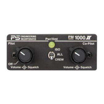
ICS is in the background. PM1000II, p/n 11920, Front Panel Both pilot and copilot have transmit capabilities over the radio. The PM1000II allows only the person who Scope presses their PTT to be heard over the aircraft radio. If... -
Page 3: Section 2 Installation
1.Using the template, drill six holes in the instrument install new headset jacks into the aircraft and connect panel in a location convenient to the pilot position them directly to the appropriate pins of the PM1000II. (s). See the wiring diagram for all details of the wire har- 2.Insert the PM1000II from behind the instrument... - Page 4 2.4.1 Electrical Noise Issues Note: Use the low level (or line) output from any music device to connect to the PM1000II. Maximum input level is 2 V peak-to-peak. WARNING: You must use separate shielded cables DO NOT USE SPEAKER OUTPUT.
-
Page 5: Section Iii Operation
Regardless of configuration, the pilot will always hear the aircraft radio. NOTE: If there is a power failure to the PM1000II, or if the power switch is turned off, the copilot will not hear the aircraft radio. Only the pilot is connected directly to PM1000II w/out crew, p/n 11922 the aircraft radio. -
Page 6: Section 4 Warranty And Service
The pilot will not hear any- Factory Service thing when he speaks into the mic on intercom. Copi- The PM1000II is covered by a one-year limited war- lot and passengers will hear themselves and music but ranty. See warranty information. -
Page 7: Appendix C Instructions For Continuing Air- Worthiness
(Airframe, Powerplant, Propeller, or Appli- items behind the instrument panel. ance) In the case of the PM1000II , you may use the following text as a guide. Installed 4-place intercom, PS Engineering... - Page 8 PM1000II with crew, p/n 11920 11920 Sub-D DB-25 Female (Sockets) on unit Power In 11-33 VDC Ground To Aircraft Radio A/C Radio Phone Audio Hi Phone Hi A/C Radio Phone Audio Lo AUX Headphone Jack To Aircraft Radio Phone Low...
- Page 9 PM1000II NO crew, p/n 11922 11922 Sub-D DB-25-- Unit has female (socket) Power In 11-33 VDC Ground To Aircraft Radio A/C Radio Phone Audio Hi Phone Hi A/C Radio Phone Audio Lo AUX Headphone Jack To Aircraft Radio Phone Low...
Need help?
Do you have a question about the PM1000II and is the answer not in the manual?
Questions and answers