PS Engineering PMA7000B Series Pilot's Manual And Operation Manual
Audio selector panel marker beacon receiver and stereo intercom system
Hide thumbs
Also See for PMA7000B Series:
- System installation and operation manual (36 pages) ,
- System installation and operation manual (34 pages)
Table of Contents
Advertisement
Quick Links
PMA7000B
-
Series
PMA7000B
-
Series
Audio Selector Panel
Marker Beacon Receiver
and
Stereo Intercom System
Pilot's Guide
Pilot's Guide
And
And
Operation Manual
Operation Manual
Flying Never Sounded So Good!™
Patent No. 5,903,277 & 6,160,496
FAA-Approved TSO C50c, C35d
JAA-Approved JTSO 2C35d, C50c
202-780-0001
Revision 1
May 2002
PMA7000B Pilot Guide
202-780-0001
1
Advertisement
Table of Contents

Subscribe to Our Youtube Channel
Related Manuals for PS Engineering PMA7000B Series


Summary of Contents for PS Engineering PMA7000B Series
- Page 1 PMA7000B Series PMA7000B Series Audio Selector Panel Marker Beacon Receiver Stereo Intercom System Pilot’s Guide Pilot’s Guide Operation Manual Operation Manual Flying Never Sounded So Good!™ Patent No. 5,903,277 & 6,160,496 FAA-Approved TSO C50c, C35d JAA-Approved JTSO 2C35d, C50c 202-780-0001 Revision 1 May 2002 PMA7000B Pilot Guide...
-
Page 2: Power Switch (Emg-Fail Safe Operation)
1 OPERATION GENERAL INFORMATION 1.1 SCOPE This section provides detailed operating instructions for the PS Engineering PMA7000B Audio Selector Panel/Intercom Systems. Please read it care- fully before using the equipment so that you can take full advantage of its capabilities. -
Page 3: Microphone (Xmt) Selection (All Models)
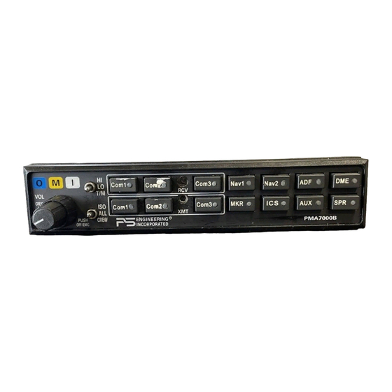
1.3 Microphone (XMT) Selection (All models) There are six pushbuttons associated with the communications transceivers. The lower buttons control which transceiver is selected for transmit. The PMA7000B gives priority to the pilot’s PTT. If the copilot it transmit- ting, and the pilot presses his PTT, the pilot’s microphone will be heard over the selected com transmitter. -
Page 4: Audio Selector (All Models)
1.4 Audio Selector (All models) Receiver audio is selected through seven momentary, push-button, backlit switches. You will always hear the audio from the transceiver that is se- lected for transmit. The users can identify which receivers are selected by noting which of the green switch LEDs are illuminated. -
Page 5: Split Mode Ics
Split mode, particularly on adjacent frequencies. PS Engineering makes no warranty about the suitability of Split Mode in all aircraft conditions. Note: Split Mode does not turn off other (Nav, ADF, etc.) selected audio to pilot. -
Page 6: Intercom Volume Control
Although no damage to the unit will occur, all passengers will lose one channel, unless they switch to the “MONO” mode on the headset. PS Engineering modifies headsets to add stereo capability, using high- fidelity speakers. Contact factory for details. - Page 7 transmissions. : (Middle Position): All parties will hear the aircraft radio and inter- com. Crew will hear Entertainment 1, passengers will hear Entertainment 2. During any radio or intercom communications, the music volume automati- cally decreases. The music volume increases gradually back to the original level after communications have been completed.
-
Page 8: Entertainment Input
1.6.4 Entertainment Input The audio selector panel has provisions for two separate entertainment in- put devices. Music 1 feeds the pilot and copilot positions, music 2 feeds the passenger positions. They operate independently in the PMA7000B. While in the ISO (Isolate) mode, the copilot will hear Entertainment 1 while the four passengers will hear Entertainment #2. -
Page 9: Marker Beacon
discrete switches mounted adjacent to the headset jacks. When Com 3 is active in the duplex mode, the TX button will blink about twice as fast as the normal transmit rate. When the intercom is in ALL mode, the pilot can speak on the phone only if the Com 3 is selected for transmit (Com 3 Xmt button activated). -
Page 10: Concurrent Messages
outer marker beacon about a mile out. Then select the “LO” sensitivity to give you a more accurate location of the Outer Marker. The momentary down switch position is marker test, labeled "T/M" and illuminates all three lamps simultaneously to assure the lamps (internal and external) are in working order. -
Page 11: Factory Service
All domestic transportation charges for returning the exchange or repaired unit to the purchaser will be borne by PS Engineering, Inc. The risk of loss or damage to the product is borne by the party making the shipment, unless the pur- chaser requests a specific method of shipment. - Page 12 Commercial use is strictly prohibited. For further information contact the Publications Man- ager at PS Engineering, Inc., 9800 Martel Road, Lenoir City, TN 37772. Phone (865) 988- 9800...
Need help?
Do you have a question about the PMA7000B Series and is the answer not in the manual?
Questions and answers