PS Engineering PMA7000B System Installation And Operation Manual
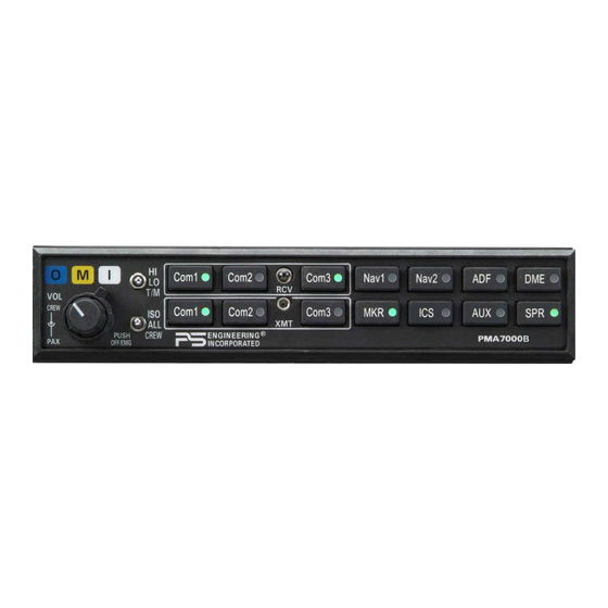
Audio selector panel with marker beacon receiver high-fidelity stereo intercom
Hide thumbs
Also See for PMA7000B:
- Pilot's manual and operation manual (13 pages) ,
- System installation and operation manual (34 pages)
Table of Contents
Advertisement
Quick Links
9800 Martel Road
Lenoir City, TN 37772
www.ps-engineering.com
P
M
A
7
0
0
0
B
P
M
A
7
0
0
0
B
Document P/N 200-780-0004
Feb. 2004
Audio Selector Panel with Marker Beacon Receiver
High-fidelity Stereo Intercom
System Installation and Operation Manual
FAA-Approved TSO C50c, C35d
JAA-Approved JTSO C50c, 2C35d
Patented under one or more of the following; No. 5,903,277; 6,160,496 and
6,493,450
In certified aircraft, warranty is not valid unless this product is installed by an
Authorized PS Engineering dealer.
PS Engineering, Inc. 2004 ©
Copyright Notice
Any reproduction or retransmittal of this publication, or any portion thereof, without the expressed written permission of PS
Engineering, Inc. is strictly prohibited. For further information contact the Publications Manager at PS Engineering, Inc., 9800
Martel Road, Lenoir City, TN 37772. Phone (865) 988-9800, email avionics@ps-engineering.com.
Advertisement
Table of Contents

Related Manuals for PS Engineering PMA7000B


Summary of Contents for PS Engineering PMA7000B
- Page 1 Any reproduction or retransmittal of this publication, or any portion thereof, without the expressed written permission of PS Engineering, Inc. is strictly prohibited. For further information contact the Publications Manager at PS Engineering, Inc., 9800 Martel Road, Lenoir City, TN 37772. Phone (865) 988-9800, email avionics@ps-engineering.com.
-
Page 2: Table Of Contents
UBLIC DDRESS UNCTION 2.4.14 (J2, P A) ..................2-6 ONTROL UTPUT 2.4.15 ....................... 2-6 NTERCOM WIRING 2.4.16 PMA7000B I (J2, P P, S, C) ........2-7 NTERCOM EXPANSION 2.4.17 (J2, P 19- O 1, ONLY)......2-7 LAYBACK BUTTON NSTALLATION PTIONS 2.4.18... - Page 3 PS Engineering PMA7000B Series Audio Selector Panel and Intercom System Installation and Operator’s Manual 2.10 ........................2-11 NSTALLATION 2.10.1 ..................2-11 PERATIONAL HECKOUT 2.10.2 ....................2-12 ECEIVER ENSITIVITY 2.11 ................... 2-12 ELLULAR NTERFACE HECKOUT 2.12 )................ 2-12 NTERNAL ECORDER HECKOUT PTIONAL 2.13...
-
Page 4: Section I General Information
Other options may be applied for exclusive use by specific aircraft manufacturers, under Type Certification. Call for information. Where the functions are identical to all units, it will be referred to herein as a PMA7000B. Otherwise, the applicable units will be specified. -
Page 5: Approval Basis
Off (Fail-safe) position. A six-station voice activated (VOX) intercom is included in the PMA7000B. This system has PS Engineer- ing’s exclusive IntelliVox® circuitry that eliminates manual adjustments. The system contains six separate VOX mic circuits, and only opens the microphone channel in use. -
Page 6: Equipment Supplied
EQUIPMENT SUPPLIED 1 ea. of the following units: Model Description Part Number PMA7000B PMA7000B Audio Panel with Marker Beacon and Stereo inter- 7000 ( ) com. PMA7000B Opt 2 PMA7000B Audio Panel without Marker receiver 7000 Opt 2 PMA7000B Installation Kit: 250-007-0002... -
Page 7: Equipment Required But Not Supplied
002-250-7028 Pilot’s Guide 202-070-0001. EQUIPMENT REQUIRED BUT NOT SUPPLIED Circuit Breaker: 1 ea; 3 amp PULL TYPE REQUIRED for PMA7000B Speaker, 4 Ω Headphone Jacks (Stereo, as Required) Microphone Jacks (as Required) Headphones, 150 Ω (Stereo), up to 6 as required Microphones, up to 6 as required Marker Antenna (75 MHz, VSWR <1:1.5, and appropriate for the airspeed) -
Page 8: Section Ii - Installation
Section 1.6 (B). If any claim is to be made, save the shipping material and contact the freight carrier. Do NOT return units damaged in shipping to PS Engineering. If the unit or ac- cessories show any sign of external shipping damage, contact PS Engineering to arrange for a replacement. -
Page 9: Audio Panel Tray And Connector Assembly
Audio Panel Tray and Connector Assembly The unit connectors mate directly with the circuit boards in the PMA7000B. The connectors are a Molex crimp-type, and require the use of a Molex hand crimp tool, EDP P/N 11-01-0203, CR6115B (or equiv.). -
Page 10: Noise
There must be at least 13.8 VDC present at the bottom connector, pin 20, of the PMA7000B for the power supply to work in its designed regulation. Otherwise, it cannot adequately attenuate power line noise. Shielding can reduce or prevent radiated noise (i.e., beacon, electric gyros, switching power supplies, etc.) However, installation combinations can occur where inter-... -
Page 11: Communications Push-To-Talk
King Radio KX170-series, require a resistive load to prevent damage if their speaker amplifier is not used. Connect the speaker output from the unit to the load input on the PMA7000B (J1, pins 19 and L, 16 and M. The speaker load is 16 Ω, 3W. -
Page 12: Transmit Interlock
Unauthorized use of unapproved cellular telephone devices in aircraft is subject to FCC enforcement action, which may include a $10,000 fine per incident. PS Engineering, Inc. does not endorse using unapproved cellular telephone equipment in flight, and takes no responsibility for the user’s action. -
Page 13: Pa Mute (J1, Pin 18)
NOTE: The top connector harness can be custom made by PS Engineering, Inc. Simply call the factory and obtain a wire harness work-sheet. The harness will be made to your specifications and fully function- ally tested. -
Page 14: Pma7000B Intercom Expansion (J2, Pins P, S, And C)
All additional entertainment devices must be switched off for both takeoff and landing. 2.4.15.1.2 Entertainment 2 Mute (Pin V) The ICS button on the PMA7000B controls the muting (“Karaoke mode”) of entertainment source #1. Connecting J2 pin V to ground through a SPST switch places the entertainment #2 music source into the Karaoke Mode. -
Page 15: Marker Beacon Installation
NOTE: PS Engineering can only provide input information at this time. Approval basis is the responsibility of the installer. Contact PS Engineering for more information. Marker Beacon Installation The marker beacon receiver is an option included in the PMA7000B. Non-marker (PMA7000) units can provide audio interface with the external receiver (see section 2.5.4). -
Page 16: Communications Antenna Installation Notes
The copilot hook switch is a SPST switch that connects pin L of J2 on the PMA7000B to ground to place the copilot mic audio on the Com 3 audio in duplex mode for cell phone operation. -
Page 17: Output
PS Engineering PMA7000B Series Audio Selector Panel and Intercom System Installation and Operator’s Manual 2.8.2 Audio Active Output (Not available with Option 1-DRAWS) Pin 20 on the top board (and PA Mute Pin 18 on the bottom board) should be connected to Apollo CNX80 for audio message prioritization, refer to CNX80 installation manual for details. -
Page 18: Post Installation Checkout
Unit Installation To install the PMA7000B, gently slide the unit into the mounting rack until the hold-down screw is en- gaged. While applying gentle pressure to the face of the unit, tighten the 3/32" hex-head in the center of the unit until it is secure. -
Page 19: 2.11.2 Receiver Sensitivity
PS Engineering PMA7000B Series Audio Selector Panel and Intercom System Installation and Operator’s Manual 17. Verify that the audio selector panel system does not adversely affect any other aircraft system by sys- tematically switching the unit on and off, while monitoring the other avionics and electrical equipment on the aircraft. -
Page 20: Section Iii Operation
There are six pushbuttons associated with the communications transceivers. The lower buttons control which transceiver is selected for transmit. The PMA7000B gives priority to the pilot’s PTT. If the copilot it transmitting, and the pilot presses his PTT, the pilot’s microphone will be heard over the selected com transmitter. -
Page 21: Swap Mode (Switch From Com 1 To Com 2 Remotely)
3.4.2 Key “Click” The PMA7000B is equipped with a “click” function that provides an aural feedback to the user in addition to the tactile button push. This sound can be enabled or disabled by simultaneously holding the COM 1 and COM 2 buttons in for at least 5 seconds. -
Page 22: Split Mode Ics
Split mode, particularly on adjacent frequencies. PS Engineering makes no warranty about the suitability of Split Mode in all air- craft conditions. Note: Split Mode does not turn off other (Nav, ADF, etc.) selected audio to pilot. However, the copilot will only hear the selected communications receiver. -
Page 23: Intercom Volume Control
All passenger headsets are connected in parallel. Therefore, if a monaural headset is plugged in to a PMA7000B Stereo installation, one channel will be shorted. Although no damage to the unit will occur, all passengers will lose one channel, unless they switch to the “MONO” mode on the headset. PS Engineering modifies headsets to add stereo capability, using high-fidelity speakers. -
Page 24: Telephone Mode
Entertainment Input The audio selector panel has provisions for two separate entertainment input devices. Music 1 feeds the pilot and copilot positions. They operate independently in the PMA7000B. The volume control does not affect the music level. While in the ISO (Isolate) mode, the copilot will hear Entertainment 1 while the four passengers will hear Entertainment #2. -
Page 25: Marker Beacon Operation (If Present)
In ISO intercom mode, when the PMA7000B is in the Com 3 mode, the pilot position is in the "Phone Booth." Only the pilot will hear the telephone, and only he will be heard. He will also have access to Com 1 or 2, and will transmit on that radio using the PTT. -
Page 26: Audio Messaging System (Option 1)
3.10 Audio Messaging system (Option 1) When this option is installed, the PMA7000B contains six stored messages. An outside annunciator, such as an Electronics International engine gage system triggers these messages. When there is an announce- ment, it will be repeated every two seconds until the remote- mounted ACK button is pushed. -
Page 27: Section Iv- Warranty And Service
PS Engineering, Inc. The risk of loss or damage to the product is borne by the party making the shipment, unless the purchaser requests a specific method of shipment. In this case, the purchaser assumes the risk of loss. - Page 28 PS Engineering PMA7000B Audio Selector Panel and Intercom System Installation and Operator’s Manual Appendix A Extern al PTT Hook Up Part of the installation includes the installation of PTT (Push To Talk) switches that allow the use of your aircraft radio for communications transmissions.
-
Page 29: Appendix B - Pma 7000B Installation Drawing
PS Engineering PMA7000B Audio Selector Panel and Intercom System Installation and Operator’s Manual Appendix B – PMA 7000B Installation Drawing 1.315 in Cutout size for front mount installation (33.4 mm) 6.31in (160.3 mm) 6.65 in (167 mm) Side View 0.60 in (15.25 mm) 1.31 in... -
Page 30: Appendix C Bottom Connector Interconnect
Ext. Mkr Audio 14. External marker audio input to Pin 21 for Mkr Audio In Lo units without internal receiver only. 15. Mic bias is not required by the PMA7000B, however, ADF Receiver ADF Audio Hi ADF Audio Lo it may be left connected if present. -
Page 31: Appendix D Top Connector Interconnect
PS Engineering PMA7000B Audio Selector Panel and Intercom System Installation and Operator’s Manual Appendix D Top Connector Interconnect PMA7000B J2 TOP CONNECTOR Pilot Phones (L) -see bottom connector. Copilot Phones (L) Copilot PhonesJack Copilot Phones (R) Copilot Phones Lo Pass. Phones (L) Pass. -
Page 32: Instructions For Faa Form 337, Audio Panels
One method of airworthiness approval is through an FAA Form 337, Major Repair and Alteration (Airframe, Power- plant, Propeller, or Appliance) In the case of the PMA7000B, you may use the following text as a guide. Installed audio selector and 6-place intercom, PS Engineering PMA7000B, part number 7000 (X) in ( location ) at station . - Page 33 PS Engineering PMA7000B Audio Selector Panel and Intercom System Installation and Operator’s Manual Appendix F RTCA DO160C (EUROCAE ED-14) Environmental Qualification Form Audio Selector Panel/Intercom/Marker Beacon Receiver 9Part Number: 7000( ) FAA TSO Number: C50c, C35d Class A, JTSO 2C35d and JTSO C50c...
-
Page 34: Cross Reference For Bendix/King Kma26
PS Engineering PMA7000B Audio Selector Panel and Intercom System Installation and Operator’s Manual Cross reference for Bendix/King KMA26 KMA26 PMA7000B KMA26 PMA7000B Function Function P261 Bottom Top P262 Bottom Aircraft Power Reserved Power Ground Music 1 L Hi 28 V Lighting... - Page 35 MKR SPR Power V Music Mute Enable Power Ground This information is for reference only. PS Engineering, Inc. does not make as- sertion that the cross reference is accurate or complete for all installations. Consult the manufacturer’s installation manuals PMA7000B...
-
Page 36: Cross-Reference For Gma340
PS Engineering PMA7000B Audio Selector Panel and Intercom System Installation and Operator’s Manual Cross-reference for GMA340 GMA340 PMA7000B GMA340 PMA7000B Function Function Mkr Ant Pilot Phones Lo Mkr Ant Lo Copilot Phn Lo Com 3 Audio in Copilot Phn (L)
Need help?
Do you have a question about the PMA7000B and is the answer not in the manual?
Questions and answers