Table of Contents
Advertisement
O
M
I
High
Low
Test
V
o
l
Iso
u
All
m
Push
Crew
e
(Fail-Safe)
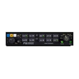
High-fidelity Stereo Audio Selector Panel
In certified aircraft, warranty is not valid unless this product is installed by
Any reproduction or retransmittal of this publication, or any portion thereof, without the expressed written permission of PS
Engineering, Inc. is strictly prohibited. For further information contact the Publications Manager at PS Engineering, Inc., 9800
Martel Road, Lenoir City, TN 37772. Phone (423) 988-9800
9800 Martel Road
Lenoir City, TN 37772
PMA7000S
PMA7000M-S
with Options
Com 1
Nav 1
Com 2
Nav 2
ENGINEERING
R
INCORPORATED
Document P/N 200-070-0006
Revision 6, Nov 1998
FAA-Approved TSO C50c, C35d
Intercom System
Installation and Operation Manual
an Authorized PS Engineering dealer.
PS Engineering, Inc. 1998 ©
Copyright Notice
MKR
ADF
DME
ICS
AUX
SPR
PMA7000M-S
Com 1
Com 1/2
Com 2
Com 2/1
Com 3
Tel
Transmit
Swap
Advertisement
Table of Contents

Subscribe to Our Youtube Channel
Related Manuals for PS Engineering PMA7000S


Summary of Contents for PS Engineering PMA7000S
-
Page 1: Intercom System
Any reproduction or retransmittal of this publication, or any portion thereof, without the expressed written permission of PS Engineering, Inc. is strictly prohibited. For further information contact the Publications Manager at PS Engineering, Inc., 9800 Martel Road, Lenoir City, TN 37772. Phone (423) 988-9800... -
Page 2: Table Of Contents
Table of Contents 1 SECTION I GENERAL INFORMATION ..............1-1 INTRODUCTION ..................... 1-1 SCOPE ........................1-1 EQUIPMENT DESCRIPTION ................. 1-1 APPROVAL BASIS - FAA..................1-2 SPECIFICATIONS....................1-3 EQUIPMENT SUPPLIED..................1-4 EQUIPMENT REQUIRED BUT NOT SUPPLIED..........1-4 LICENSE REQUIREMENTS................... 1-4 2 SECTION II - INSTALLATION ..................2-1 GENERAL INFORMATION.................. - Page 3 PS Engineering PMA7000M-S Series Audio Selector Panel and Intercom System Installation and Operator’s Manual 2.10 ................2-12 NSTALLATION HECKOUT 2.11 ....................2-12 NSTALLATION 2.11.1 .................. 2-12 PERATIONAL HECKOUT 2.11.2 ..................2-13 ECEIVER ENSITIVITY 2.12 ............... 2-13 ELLULAR NTERFACE HECKOUT 2.13 .................
-
Page 4: Section I General Information
Warning: Use of non-aviation approved cellular telephone equipment is prohibited by regulation. PS Engineering is not responsible for unauthorized use of cellular telephones. The PMA7000M-S is only interfaced to the Trimble TrimConnect 3100 D at this time. There are two unswitched inputs, for autopilot disconnect, and/or radar altimeter warning. -
Page 5: Approval Basis - Faa
Landing System (ILS) approach. APPROVAL BASIS - FAA TSO Approval. The PMA7000M-S, and PMA7000S Audio Selector Panels are FAA approved under TSO C50c (Audio Amplifiers) and TSO C35d (Marker Beacon Receivers). All systems comply with relevant portions of RTCA DO-143 (Marker Beacon Receivers),... -
Page 6: Specifications
PS Engineering PMA7000M-S Series Audio Selector Panel and Intercom System Installation and Operator’s Manual Operation is subject to the following conditions: This device may not cause harmful interference. This device must accept any interference received, including interference that may cause undesired operation. -
Page 7: Equipment Supplied
PS Engineering PMA7000M-S Series Audio Selector Panel and Intercom System Installation and Operator’s Manual Intercom Specifications Intercom Positions: 6 places (with individual IntelliVOX circuits) Music Inputs: 2 (Stereo) Music Muting: >-50 dB "Soft Mute" when Com or intercom ac- tive. -
Page 8: Section Ii - Installation
PS Engineering to arrange for a replacement. Under no circumstances attempt to install a damaged unit in an aircraft. Equipment re- turned to PS Engineering for any other reason should be shipped in the original PS Engi- neering packaging, or other UPS approved packaging. -
Page 9: Equipment Installation Procedures
It is imperative that correct wire be used. Refer to FAA Advisory Circular 43.13-2A for more information. Failure to use correct techniques may result in improper operation, electrical noise or unit failure. Damage caused by improper installation will void the PS Engineering warranty. 200-070-0006 Page 2-2... -
Page 10: Noise
PS Engineering PMA7000M-S Series Audio Selector Panel and Intercom System Installation and Operator’s Manual 2.4.1 Noise Due to the variety and the high power of radio equipment often found in today's general aviation aircraft, there is a potential for both radiated and conducted noise interference. -
Page 11: Power
PS Engineering PMA7000M-S Series Audio Selector Panel and Intercom System Installation and Operator’s Manual 2.4.3.1 Stereo PMA7000M-S installations into monaural PMA6000, PMA6000M. Installations replacing PMA6000 or PMA6000M require re-wiring of the top connector to accommodate the stereo configuration. See appendixes for detailed interconnect informa- tion. -
Page 12: Unswitched Inputs
MIL-spec cable as shown. Connect the shields at the audio panel end only, and tie to the audio low inputs as shown. NOTE: The top connector harness can be custom made by PS Engineering, Inc. Simply call the factory and obtain a wire harness work-sheet. The harness will be made to your specifications and fully functionally tested. -
Page 13: Com 3 Audio
PS Engineering PMA7000M-S Series Audio Selector Panel and Intercom System Installation and Operator’s Manual system incorporates a "Soft Mute" system. This will mute the entertainment devices dur- ing ICS or radio conversation. Any signal appearing in the unswitched audio inputs will always mute the entertainment sources, even though the passengers may not hear the audio tone itself. -
Page 14: Irs Installation (Option 1, And 2)
Map” Other combinations can be created at additional cost. NOTE: PS Engineering can only provide input information at this time. Approval basis is the responsibility of the installer. Contact PS Engineering for more information. Marker Installation (PMA7000M-S) The marker beacon receiver is an option included in the PMA7000M-S. Non-marker (PMA7000S) units can provide audio interface with the external receiver (see section 2.5.4). -
Page 15: External Marker Lights (7000Ms)
PS Engineering PMA7000M-S Series Audio Selector Panel and Intercom System Installation and Operator’s Manual 2.5.2 External Marker Lights (7000MS) For installations that require external marker beacon lights, there are three outputs that can drive 12-Volt lamps only. The external output lamps are driven high (+9 VDC ±1.5 VDC) when active. -
Page 16: Wireless Telecommunications Interface
Unauthorized use of cellular telephone devices in aircraft is subject to FCC enforcement action, which may include a $10,000 fine per incident. PS Engineering, Inc. does not endorse using unap- proved cellular telephone equipment in flight, and takes no responsibility for the user’s action. - Page 17 PS Engineering PMA7000M-S Series Audio Selector Panel and Intercom System Installation and Operator’s Manual PMA7000M-S J2, pin M is the passenger hook switch. Install a SPST switch in a location adjacent to each passenger headset where cellphone use is desired. When pin M is con- nected to ground through any switch, the passenger microphones are all on the cellphone system.
-
Page 18: Pma7000M-S Pin Assignments
PS Engineering PMA7000M-S Series Audio Selector Panel and Intercom System Installation and Operator’s Manual 2.9 PMA7000M-S Pin assignments J2 PMA7000S, 7000MS (Stereo) Top Connector J1 Bottom Connector (Mono & Stereo) Chassis Ground Pilot Phone Audio Hi (Left) MKR Coax Lo... -
Page 19: Ps Engineering
After wiring is complete, verify power is ONLY on pin 20 of the J1 (bottom connector), and airframe ground on bottom connector pin Z. Failure to do so will cause serious inter- nal damage and void PS Engineering's warranty. 2.11 Unit Installation To install the PMA7000M-S, gently slide the unit into the mounting rack until the hold- down screw is engaged. -
Page 20: Receiver Sensitivity
PS Engineering PMA7000M-S Series Audio Selector Panel and Intercom System Installation and Operator’s Manual 15. Verify that the audio selector panel system does not adversely affect any other aircraft system by systematically switching the unit on and off, while monitoring the other avi- onics and electrical equipment on the aircraft. -
Page 21: Digital Annunciation Checkout
Complete log book entry, FAA Form 337, weight and balance computation and other documentation as required. Sample text for FAA Form 337, and instructions for continu- ing airworthiness can be found in Appendix F. Return completed warranty registration application to PS Engineering. 200-070-0006 Page 2-14... -
Page 22: Section Iii Operation
SCOPE This section provides detailed operating instructions for the PS Engineering PMA7000M- S, and PMA7000S Audio Selector Panel/Intercom Systems. Please read it carefully before using the equipment so that you can take full advantage of its capabilities. This section is divided into four sections covering the basic operating areas of the PMA7000M-S systems. -
Page 23: Speaker Amplifier
PS Engineering PMA7000M-S Series Audio Selector Panel and Intercom System Installation and Operator’s Manual tons is pressed, it will stay in the "in" position. Press the switch again and it be in the "out" position and remove that receiver from the audio. -
Page 24: Swap Mode (Switch From Com 1 To Com 2 Remotely)
Split mode, particularly on adjacent frequencies. PS Engineering makes no warranty about the suitability of Split Mode in all aircraft conditions. Note: Split Mode does not turn off other (Nav, ADF, etc.) selected audio to pilot. However, the copilot will only hear the selected communications receiver. -
Page 25: Intercom
Moving your head through a vent air stream may cause the IntelliVox™ to open momentarily. This is normal. For optimum microphone performance, PS Engineering, Inc. recommends installation of a Microphone Muff Kit from Oregon Aero (1-800-888-6910). This will not only optimize VOX performance, but will improve the overall clarity of all your communications. -
Page 26: Intercom Modes
PMA7000M-S Stereo installation, one channel will be shorted. Although no damage to the unit will occur, all passengers will lose one channel. PS Engineering modifies headsets to add stereo capability, using high-fidelity speakers. Contact factory for details. -
Page 27: Telephone Mode
PS Engineering PMA7000M-S Series Audio Selector Panel and Intercom System Installation and Operator’s Manual When in the A mode, pilot and copilot will hear Entertainment 1 input while all passen- gers will hear the Entertainment 2 source. While in the C mode, pilot and copilot will hear entertainment input #1 while the passengers may listen to entertainment input #2. -
Page 28: Marker Beacon (Pma7000M-S)
PS Engineering PMA7000M-S Series Audio Selector Panel and Intercom System Installation and Operator’s Manual on the phone. All will hear selected audio. Com 1 audio is automatically heard in the head- sets. The pilot will have transmit capability on Com 1, simply by using the PTT switch. -
Page 29: Operation
PS Engineering PMA7000M-S Series Audio Selector Panel and Intercom System Installation and Operator’s Manual Operating as a continuous loop recorder, (first message received will be the last heard), the recorder has one minute of recording time and up to 16 messages. With its own built in VOX circuit, there are no buttons to press to start recording. -
Page 30: Section Iv- Warranty And Service
During this one-year war- ranty period, PS Engineering, Inc., at its option, will send a replacement unit at our ex- pense if the unit should be determined to be defective after consultation with a factory technician. -
Page 31: Appendix A External Ptt Hook Up
NOTE: This mod does not alter normal opera- tion. Below are some examples of typical modifications. Contact PS Engineering or the PTT manufacturer for more details if necessary. Procedures For David Clark PTT Unscrew the round black plastic cover from the jack. -
Page 32: Appendix B - Installation Drawing
PS Engineering PMA7000M-S Series Audio Selector Panel and Intercom System Installation and Operator’s Manual Appendix B – Installation Drawing 1.62 in Cutout size for front mount installation (41.15 mm) 6.31in (160.3 mm) 6.65 in (167 mm) Side View 0.60 in (15.25 mm) 1.31 in... -
Page 33: Appendix C Bottom Connector Interconnect
12. For mono versions (PMA7000, PMA7000M) connect pilot headphone as shown with 2-conductor wire. Com 3 Mic Key For stereo versions (PMA7000S and PMA7000M-S) connect pilot headphone (L) to top connector, Pin 1, using 3-conductor wire. 13. Key pin between pin 4 and 5. -
Page 34: Appendix D Top Connector Interconnect
PS Engineering PMA7000M-S Series Audio Selector Panel and Intercom System Installation and Operator’s Manual Appendix D Top Connector Interconnect PMA7000M-S J2 TOP CONNECTOR (Stereo) Pilot Phones (L) -see bottom connector. Copilot Phones (R) Copilot Phones (L) Notes: Copilot Phones Lo Pass. -
Page 35: Appendix E- Instructions For Faa Form 337 And Continuing Airworthiness
PMA7000M-S added. Aircraft equipment list, weight and balance amended. Compass compensation checked. A copy of the operation instructions, contained in PS Engineering docu- ment 200-070-0003, revision 2, July 23, 1998, is placed in the aircraft records. All... -
Page 36: Appendix F Rtca Do160C Environmental Qualification Form
Installation and Operator’s Manual 10 Appendix F RTCA DO160C Environmental Qualification Form Audio Selector Panel/Intercom/Marker Beacon Receiver Part Number: 7000S; 7000M-S FAA TSO Number: C50c, C35b Class A Manufacturer: PS Engineering Incorporated 9800 Martel Road Lenoir City TN 37772 Conditions Section Conducted Tests Temperature and Altitude Equipment tested to CAT A1 &...
Need help?
Do you have a question about the PMA7000S and is the answer not in the manual?
Questions and answers