Table of Contents
Advertisement
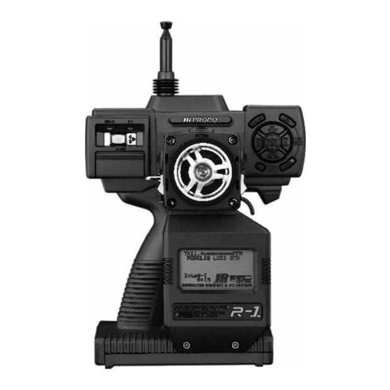
• Dot matrix graphic display
• 10 model memory
• S-Z PCM/PPM selectable
• Most sophisticated A.B.S.
braking system available
• Fully programmable 8-point
throttle and brake curve
• Five digital, fully programmable
trims with auto trim memory
• Lap timer gives record of last 99
laps, best lap, average lap, etc.
• Independently adjustable speed
steering, both turning and
returning
• Efficient battery consumption—
Alkalines last approximately
7 hours
Advertisement
Table of Contents

Subscribe to Our Youtube Channel
Related Manuals for JR Racing R-1


Summary of Contents for JR Racing R-1
- Page 1 • Dot matrix graphic display • 10 model memory • S-Z PCM/PPM selectable • Most sophisticated A.B.S. braking system available • Fully programmable 8-point throttle and brake curve • Five digital, fully programmable trims with auto trim memory • Lap timer gives record of last 99 laps, best lap, average lap, etc.
-
Page 2: Quick Start
We know you’re anxious to quickly. When you’ve got time, we suggest that you read get going with your new R-1, so we’ve provided this Quick each section in this manual to better understand the Start section that allows you to quickly set-up your new advanced features of the R-1. -
Page 3: Table Of Contents
(Direct Servo Control) Programmable Mix 1 and 2 Receiver Hook-Up Tx Mode The Key Pad Function Mode Functions General Information About Dual Rate/Exponential Programming the R-1 Sub-Trim Beeping Confirmation Travel Adjust Two-Speed Scrolling Throttle Hold Contrast Adjustment of the Display Throttle Curve... -
Page 4: Control Identification
Screwing clockwise play switch will save batteries. increases the steering tension. Note: The antenna included with the R-1 is the screw-in Display Switch type (part #JRPA160). When in use, be sure the... -
Page 5: Transmitter Module
Transmitter Module The R-1 features a replaceable module which allows for the changing of frequencies or bands. To remove the module, press the tabs located on the module inward while pulling the module out. Replacement crystals and modules are available separately, allowing frequency changes to be made. -
Page 6: Installing The Batteries
D.S.C. (Direct Servo Contro l ) The R-1 transmitter requires 8 AA batteries (not included). The R-1 features a D.S.C. function that allows the operation of To install the batteries, remove the battery door on the bot- the servos/speed controller without transmitting a signal. This... -
Page 7: Receiver Hook-Up
Receiver Hook-Up Electric Car Set-Up Electronic speed controller (optional) Steering servo DSC hook-up, see page 6 Gas Car Set-Up Throttle servo Steering servo Optional battery pack Optional switch DSC hook-up, see page 6 The Key Pad Up/Steering + Key/ Exponential Model Select Mode List Select Key/... -
Page 8: General Information About Programming The
Digital Trims There are five digital trims on the R-1 (see page 4 for loca- 1 BACK UP ERROR tions). Each digital trim is adjusted by pressing the trim but- ton in one of the two available directions. -
Page 9: Normal Display
Normal Display Steering Tension When the power switch is turned on, the normal display Steering Tension is adjustable via the recessed screw just appears. behind the idle up switch (see page 4 and 16). Turning the screw clockwise increases the steering tension. Transmitter TX11.0v Modulation... -
Page 10: System Mode 1
System Mode Also called System Set-Up Mode, this mode con- tains programming features that are usually only Normal Display adjusted once during the initial set-up of a particu- lar car, and once set, they’re seldom, if ever, changed at the track. System Mode programming Reverse Switches features include servo reversing, model name, modulation type, data transfer, etc. -
Page 11: Function Mode 1
Function Mode The R-1’s programming is laid out in two paths or modes that are accessed in different ways. Function Mode contains Dual Rate/Exponential the most commonly used programming features that you’ll likely be changing at the track to dial in you car. Features such as dual rate, expo A.B.S. - Page 12 UP and DOWN keys simultaneously—both methods will bring you back to the Normal display. The R-1 allows the racer to select between an expert mode (all the advanced programming features are accessible) or beginner mode (advanced features such as programmable Direct Mode Access mix, trim rate, etc.
- Page 13 Note: Direct Mode cannot be accessed in System Mode. To access Direct Mode from the normal display, press the MODE LISTkey once. DIRECT MODE Now press the key that you wish to access. Note: The Direct Mode function is written in orange on the key pad. Note: The Timer function is assigned at the factory to the custom –...
-
Page 14: Reverse Switch
NOTE: The functions on the following pages are accessed via the System Mode. To enter System Mode, press and hold the MODE LIST key while turning on the transmitter. Reverse Switch Reverse switch is used to select the correct direction of the In System Mode, access the Reverse Switch function by servo’s travel. -
Page 15: Function Select
Function Select Note: Each function can only be programmed to one The function select feature allows you to program the five available digital trims, the two available switches and the switch or digital trimmer. If the function you wish thumb-operated button to one of the following functions: to select is already programmed to another switch or trimmer, it must first be removed from that switch or trimmer before it can be reprogrammed... -
Page 16: Trim Rate
Trim Rate The trim rate function allows the trim authority (the amount In System Mode, access the Trim Rate function by moving of trim available) to be adjusted. This is especially useful to the cursor to Trim RATEand pressing the MODE LIST key. adjust the proper brake range available with the throttle trim Note: The Aux 3 channel can be assigned to any of the and throttle brake. -
Page 17: Model Name
Model Name The model name function allows the storing of a model’s In System Mode, access the Model Name function by name using up to eight characters. This is important for moving the cursor to MDL Name and pressing the MODE future identifications purposes in selecting a model. -
Page 18: Data Reset
Data Reset The data reset function resets all the memory (in the select- In System Mode, access the Data Reset function by moving ed model only) back to the factory default settings. the cursor to MDL Reset and pressing the MODE LIST key. [MDL Reset] MODEL 1 SPCM... -
Page 19: Modulation
Modulation The R-1 can transmit in three types of modulation — PPM SPCM is Pulse Code Modulation with a 1024 step resolu- (FM), ZPCM and SPCM. tion and is activated when using the JR 330 PCM receiver. PPM (also referred to as FM) modulation should be selected... -
Page 20: Fail-Safe
Fail-Safe (only available when PCM is activated) In PCM modulation, a fail-safe function is available that will Using the SEL key, you can set each of the three channels to cause the servos and speed controller to assume either a the fail-safe or the hold function. - Page 21 Example: Full brakes and straight steering. Press the CLR key. Press the CLR key to store the desired fail- key while holding the desired position with the throttle and safe positions. steering. A beep will indicate the position is stored and the stored value will be displayed on the bottom center of the To check that fail-safe is working correctly, turn off the screen.
-
Page 22: Transfer
Transfer The R-1 allows the memory of a model to be transferred With the power off, press and hold the MODE LIST key while from one R-1 to another. A JR trainer cord (part #JRPA130) plugging the trainer cord in the DSC jack. Do this with both is needed to complete the transfer. - Page 23 The transmitter from which you wish to transmit data should look like this: [TRANSFER] £TRANSMIT Start=[CLR] MODEL 1 Receiver stand-by ? Press the UPkey to go to Press the PAGE key to select Fail-Safe transmit or receive Press the DOWN key to go to Programmable Mix Press the CLR key to initiate transfer...
-
Page 24: Programmable Mix 1 And 2
Programmable Mix 1 and 2 The R-1 offers two programmable mixes that can be used to In System Mode, access Programmable Mixing by moving mix any two channels together. The mixing value can be the cursor to PROG.MIX and pressing the MODE LIST key. -
Page 25: Tx Mode
Tx Mode The Tx Mode allows the setting of five different transmitter In System Mode, access the Tx Mode function by moving parameters—Mode, Buzz Tone, AUX 3 Channel, Warning, the cursor to TX MODE and pressing the MODE LIST key. and D. -
Page 26: Dual Rate/Exponential
Normally expo is used to settle down a car that’s twitchy around center without giving up maximum steering response. The R-1 allows both a positive (normal) and neg- ative (increases sensitivity at neutral) exponential value. In Function Mode, access the Dual Rate/Exponential func- tion by moving the cursor to D/R &... -
Page 27: Sub-Trim
Sub-Trim In Function Mode, access the Sub-Trim function by moving Sub-trim allows you to electronically adjust the centering of your servos. Sub-trim is available for all three channels and the cursor to Sub Trim and pressing the MODE LIST key. is adjustable from 0–125% (+ or - 30% of servo travel). -
Page 28: Travel Adjust
Travel Adjust Travel adjust, also referred to as endpoint adjust or travel brake positions independently. Remember, dual rate and volume, allows the precise maximum servo throw in either brake trimmers work in unison with travel adjust. direction to be independently adjusted. The travel adjust range is from 0–150% (0 to 60 degrees servo travel). -
Page 29: Throttle Hold
Throttle Hold Throttle hold moves the throttle servo to a pre-selected Note: Activating Throttle Hold inactivates the timer as it position when the TH.HOLD button is depressed. This can uses the same button. be adjusted to give full panic brakes for emergency braking. When throttle hold is on, all throttle settings (except sub- In Function Mode, access the Throttle Hold function by trim and reverse switch) are inactive, including throttle digi-... -
Page 30: Throttle Curve
Throttle Curve The R-1 features an 8 point throttle that allows you to In Function Mode, access the Throttle Curve function by precisely adjust the throttle and brake response. Two 8 point moving the cursor to THRO CURV and pressing the MODE curves can be set up, and each can be selected with the LIST key. - Page 31 Exponential An exponential function is available that is used to smooth screen. Press the + or - key to activate or deactivate the expo out the throttle/brake curve. To activate the expo function, function. Also, pressing the CLR key in this screen will press the SEL key until EXPO appears at the center of the deactivate the expo function.
-
Page 32: Speed Adjust
Speed Adjust The R-1 allows you to adjust the steering servo’s speed pendently selected. Two separate speed adjust values can be independently away from center (turning), as well as back to set and selected using the Drive Mode switch (position 0 or center (return). -
Page 33: Advanced Braking System (A.b.s.)
Advanced Braking System (A.B.S.) The R-1 features the most advanced braking system at a pre-set delay A.B.S. braking begins. Steering mixing is available! A.B.S. works as a pulse brake, allowing greater programmed to give increased A.B.S. braking as the steering stability and control during hard braking. - Page 34 Pattern If you’d like to see how this works, program a large value (near 100%) and watch what happens to the throttle servo as you apply brakes. Normally a value of 8 to 20 is used to give maximum initial braking before going into A.B.S. If your car spins out under heavy braking, your setting here may be too high.
-
Page 35: Idle Up
Idle Up The idle up function is normally used to advance the throttle In Function Mode, access the Idle Up function by moving position slightly, making it easier to start gas cars. When the cursor to IDLE UP and pressing the MODE LIST key. turned on, the throttle servo will offset to the pre- programmed position, and “on”... -
Page 36: Quick Throttle
Quick Throttle The quick throttle feature is used to reduce/eliminate the the trigger is slightly squeezed. This gives the most accurate dead throttle area that exists at neutral to the starting point of feel and eliminates this dead area. throttle and from neutral to the starting point of braking. This area is sometimes known as dead band. -
Page 37: Timer
Timer The below is a graphic illustration showing the flow path to get to up and down timer, as well as the individual lap times, lap calc and integrated timer. [TIMER] [TIMER] £Lap/Up/Down £Lap Time ∞ INH Record 0:00.0 0:00.0 0:00.0 0:00.0 ∞... -
Page 38: Lap Timer
The R-1 features a sophisticated timing system. Three types In Function Mode, access the Timer function by moving the of timers are available — a lap timer, an up timer and a cursor to TIMER and pressing the MODE LIST key. - Page 39 Integrated Timer The integrated timer keeps track of the time the transmitter is turned on, which is useful for determining how much battery life is left. Press the PAGE key to access the above screen. Also note that Integrated Timer is displayed on the normal screen.
-
Page 40: Model Select
Model Select The R-1 has the ability to store up to ten models in its mem- In Function Mode, access the Model Select function by ory. All programmed parameters, including digital trim moving the cursor to Model SEL and pressing the MODE positions, are automatically stored in each memory. -
Page 41: Position
Position (Digital Trim and Servo Position) The POS. screens visually display the digital trim positions In Function Mode, access the Position function by moving and the servo positions. This can be helpful when making the cursor to POS. and pressing the MODE LIST key. adjustments or to see how programming changes (e.g., mixing or throttle curve) affect the servo’s movement. -
Page 42: Data Sheet 4
Data Sheet MODEL NO. _ _ _ _ _ _ _ _ ′ ′′ TOTALTIME: ALARM MODEL NAME _ _ _ _ _ _ _ _ _ _ _ _ ′ ′′ LAP TME LIST Best: M O D U L A T I O N •... -
Page 43: Warranty Coverage
Warranty Information 4. Include detailed information explaining your operation of the system and problem(s) encountered. Provide an itemized list of equipment enclosed and identify any particu- Important Note: Be sure to keep your original, dated lar area/function which may better assist our technicians in sales receipt in a safe place as you will be required addressing your concerns.
Need help?
Do you have a question about the R-1 and is the answer not in the manual?
Questions and answers