Advertisement
Quick Links
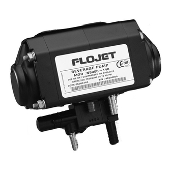
Fig #1
(Quick-Disconnect
Reversible Fittings)
Standard Configuraton
Flojet Model No. 5000-530
OPERATION
A front installation requires the following hardware, four
#8 Phillips pan head self-drilling sheet metal screws to
mount on "Area A", which in turn is mounted on the
riser/spacer of the bag-in-box rack (see fig. #1 & #6). On
a side installation, the same hardware is used, but the
area affected is "Area B" (see fig. #8). For wall
installation, four anchor bolts are provided. All pumps/
transfer valves are identified left to right as follows: #3,
#2, #1. On a standard three shelf bag-in-box rack, #3
pump services the top shelf, #2 pump services the
middle shelf and #1 pump services the bottom shelf.
This also applies to the transfer valves. For quick
installations, please note all pumps have the CO
line manifold. Only one CO
source to pump bracket assembly. A 3/8 inch (9.5 mm)
product out (quick-disconnect fitting) stainless steel
barb port is provided with every pump.
Pump bracket assemblies/transfer valve assemblies are
capable of readily accepting installation of Flojet and
Shurflo products. (See fig. #7 for proper removal of
pumps.) Pump bracket assemblies/transfer valve
assemblies adapt to the Red Line bag-in-box rack. (See
fig. #6 for routing of hose and tube hangers.)
All suction line lengths from pump inlet to box connec-
tor must not exceed 10 feet (3 m). Transfer valve is
located between pump and box and now includes 15
feet (4.6 m) of hose for special applications. Pumps must
be above bottom of corresponding box when installed
Pump
Bracket
CO2 Inlet Line
Manifold
Product Out
Lines
line is needed from CO
2
Installation Operation & Service Instructions
CO
2
3
2
C-Clips
1
on bag-in-box rack. When securing bag-in-box rack to
wall, you must allow a nominal one inch (25.4 mm)
clearance between the wall and the rear legs of the rack.
Pump Assemblies With Transfer Valves
Hose length should be no greater that five feet (1.5 mm)
vertical distance between center line of pump and
bottom of box it is pumping from.
Pump Assemblies Without Transfer Valves
Installation on bag-in-box racks must be provided for no
greater than ten feet (3 m) vertical distance between
center line of pump and bottom of box it is pumping
from.
inlet
2
Mounting Hardware For Installation Of Pump &
2
Transfer Valve Assemblies To Bag-In-Box Rack
1. Quantity of four #8 Phillips pan head self-drilling
sheet metal screws.
2. Minimum of two tube hangers per suction hose to
fasten hose to bag-in-box rack.
3. Quantity of four #8 Phillips pan head self-tapping
screws for use with anchor bolts for wall mounting.
4. Quantity of four anchor wall mounting anchors.
5. All Oetiker clamps must be stainless steel and of
step-less design.
6. Quantity of one plastic tie wrap provided for product
out hose.
Flojet N5000 Series
Operated Beverage Pump
Bracket Assembly
Area "B"
(Both Sides)
Retainer Bar
Assembly
Bumper
Guard
1
Area "A"
(Both Sides)
Tie Wrap
2
3
Advertisement

Related Manuals for FLOJET N5000 Series


Summary of Contents for FLOJET N5000 Series
- Page 1 Pump bracket assemblies/transfer valve assemblies are 2. Minimum of two tube hangers per suction hose to capable of readily accepting installation of Flojet and fasten hose to bag-in-box rack. Shurflo products. (See fig. #7 for proper removal of 3.
- Page 2 For most installations, 65 PSI (4.4 bar) will be (5.5 bar) gas pressure or manufacturer’s maximum adequate. Open dispensing valve to purge air from sys- recommended pressure. The Flojet Model N5000 has tem. Pump will now operate automatically by starting an automatic vacuum shutoff valve which stops the...
- Page 3 STANDARD THREE OR TWO PUMP FRONT MOUNTING INSTRUCTIONS Fig. #7 Fig. #8 Proper Handling Of Retainer Bar Assembly Note: Tygon Hose Center Line Run N5000-530 Front Side Mount Mount Caution! Pull retainer bar assembly from two positions on either side of pump with your fingers.
- Page 4 FLAMMABLE VAPORS ARE PRESENT • John Guest for 1/4” or 3/8” O.D. tubing, plastic U.S.A. UNITED KINGDOM Flojet Flojet, Unit 1, Avant Business Centre 20 Icon Denbigh West Industrial Estate Foothill Ranch, CA 92610-3000 Milton Keynes, Bucks, England MK1 1DL...
Need help?
Do you have a question about the N5000 Series and is the answer not in the manual?
Questions and answers