Advertisement
Quick Links
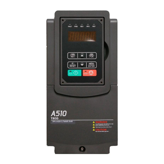
TECO A510 Inverter
Quick Start Guide
This guide is to assist you in installing and running the inverter and verify that it is
functioning correctly for it's main and basic features.
For detailed information and if there are any doubts please refer to the instruction manual.
Step 1
Supply & Motor connection
1) Ensure that the Inverter & the motor have the correct
KW power and voltage ratings.
Motor full load amps must not exceed the Inverter rating.
2) Ensure that the supply & Motor cables are connected
Correctly prior to power up.
3) Connect supply cable to terminals L1,L2& L3.
4) Connect motor cable to terminals T1,T2 &T3.
(Swap two leads If motor runs in reveres direction).
5) Connect supply Earth and the motor Earth to the drive Earth
terminal.
Page 1 of 10
Note:-
I ) For detailed installation
and wiring refer to the
manual.
Instruction
11/07/14
Advertisement

Related Manuals for TECO A510


Summary of Contents for TECO A510
-
Page 1: Quick Start Guide
TECO A510 Inverter Quick Start Guide This guide is to assist you in installing and running the inverter and verify that it is functioning correctly for it’s main and basic features. For detailed information and if there are any doubts please refer to the instruction manual. -
Page 2: Reset Key
Step 2 Apply power to the drive Apply power to the drive, the display will briefly show the supply voltage 220V followed by flashing. 05.0 This is the default ( factory set) frequency. If the unit has been used previously then it will show the last frequency programmed. - Page 3 Remote speed reference and Remote run Step 1 Remote mode wiring. Speed reference and Run signals. 1) Ensure that you have carried out installation & wiring requirements as per step1 quick start guide on previous page before you proceed. 2) For analogue signal type. -10V to +10V or 0-10V dc. Use the terminal AI1 or AI2.
- Page 4 Step 4 using remote speed reference. (Potentiometer, 0-10vdc or 4-20ma ) 1) To run. Activate the remote run switch connected to terminals S1 ( FWD) or S2 ( REV) as required,. Parameter 00-02=0001 The frequency will ram up to the frequency set by one of the Following and according to the set acceleration ramp time.
- Page 5 Type Name Functions Main digital Frequency, parameter, voltage, current, temperature and displays Fault message. FAULT: When the inverter has a warning or fault message, the indicator lights up. FWD: When the inverter is in forward run mode, the indicator lights up. RUN mode: Continuously ON.
- Page 6 Basic Quick Start Parameter List Parameter Default Range Note 00-00 Control Mode:- 0: V/F 1: V/F+PG (Encoder). 2: SLV ( Sensorless Vector) 3: SV ( Vector +Encoder) 4: PMSV ( Permanent Magnet Motor + Encoder) 00-27 HD/ND selection 0: HD (Heavy duty load mode) 1: ND (Normal duty load mode) 00-02 00-00...
- Page 7 Control Modes & Auto Tune A510 provides five control modes Select the relevant control mode for the application. Default control mode is V/f. V/f can be used for most applications specifically multi-motor or applications where auto tune is not successful or when a customized v/f pattern may be required.
- Page 8 SLV & SV mode set parameters in parameter Group 17. Three auto tune modes are available. Rotational/ Static & Resistance. Selected by parameter 17-00 Use rotational where possible. Motor rotates the process takes about 50 secs Use Static when rotation of load is not possible. It takes about 35 secs. ...
- Page 9 Note:- No-load motor voltage (02-19) & 17-08 Parameter determines the rated flux during motor’s rated rotation in SLV or SV control mode. Set the value of this parameter to the same value as parameter 17-08. A value of 10~50V below the rated input voltage level (parameter 17-03) ensures that the motor is capable of providing adequate torque performance when operating at nominal speed (or higher speed).
-
Page 10: Wiring Diagram
Wiring Diagram Braking resistor 煞車電阻 B1/P R/L1 U/T1 Main circuit S/L2 V/T2 power 主迴路電源 T/L3 W/T3 The third type grounding. 第三種接地 Resistance lower than 100 ohm. 電阻值100以下 正向運轉/停止 Forward Analog output 類比輸出1 rotation/stop Reversal rotation/stop 反向運轉/停止 Analog signal output 1, 2 類比信號輸出1, 2 類比輸出2 Analog output...
Need help?
Do you have a question about the A510 and is the answer not in the manual?
Questions and answers