Table of Contents
Advertisement
Advertisement
Table of Contents

Related Manuals for Lang 224Z


Summary of Contents for Lang 224Z
-
Page 1: Maintenance Instructions
Installation, Operation, and Maintenance Instructions Gas Griddle Models: 224Z 260Z 236Z 272Z 248Z Star Manufacturing International 10 Sunnen Drive St. Louis, MO.63143-3800 Part Number: 2M-W359 Ph: 314-781-2777 Fax: 314-781-2714 WWW.STAR-MFG.COM Rev. C October 29, 2007... -
Page 2: Safety
Safety CAUTION: THE GRIDDLE IS EXTREMELY HEAVY. FOR SAFE HANDLING, INSTALLER SHOULD OBTAIN HELP AS NEEDED, OR EMPLOY APPROPRIATE MATERIALS HANDLING EQUIPMENT (SUCH AS A FORKLIFT, DOLLY, OR PALLET JACK) TO REMOVE THE UNIT FROM THE SKID AND MOVE IT TO THE PLACE OF INSTALLATION. - Page 3 THIS MANUAL MUST BE RETAINED FOR FUTURE REFERENCE. READ, UNDERSTAND AND FOLLOW THE INSTRUCTIONS AND WARNINGS CONTAINED IN THIS MANUAL. DANGER POTENTIALLY HAZARDOUS SITUATION WHICH, IF NOT AVOIDED, COULD RESULT IN DEATH. POTENTIALLY HAZARDOUS SITUATION WHICH, IF NOT WARNING AVOIDED, COULD RESULT IN DEATH OR SERIOUS INJURY. CAUTION POTENTIALLY HAZARDOUS SITUATION WHICH, IF NOT AVOIDED, MAY RESULT IN MINOR OR MODERATE INJURY.
-
Page 4: Table Of Contents
CHAPTER PAGE Safety ....................2 Table Of Contents ................4 Equipment Description ..............7 Unpacking ..................9 Installation ..................10 Initial Start-Up.................. 13 Operation..................14 Cleaning Procedures............... 19 Troubleshooting................20 Exploded View................. 22 Parts List ..................23 Wiring Diagram................28... - Page 5 IMPORTANT READ FIRST IMPORTANT THE GRIDDLE IS EXTREMLY HEAVY. FOR SAFE HANDLING, INSTALLER SHOULD OBTAIN HELP AS NEEDED, OR EMPLOY APPROPRIATE CAUTION MATERIALS HANDLING EQUIPMENT (SUCH AS A FORKLIFT, DOLLY, OR PALLET JACK) TO REMOVE THE UNIT FROM THE SKID AND MOVE IT TO THE PLACE OF INSTALLATION.
- Page 6 Never leave a chlorine sanitizer in contact with stainless steel surfaces NOTICE longer than 10 minutes. Longer contact can cause corrosion. Service on this or any other Lang Manufacturing appliance must be performed by qualified personnel only. Consult your authorized service NOTICE agent directory or call the factory at 1-800-807-9054, or visit our website at WWW.STAR-MFG.COM...
-
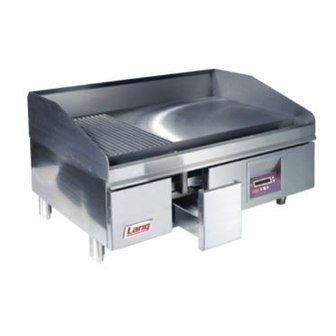
Page 7: Equipment Description
Equipment Description Exterior Construction • The griddle dimensions are 17” (43.18cm) High, 30” (76.20cm) Deep, and width is dependent on the actual model number. • The sidewall is constructed of double wall stainless steel, which allows closer installation to combustible surfaces. •... - Page 8 ELECTRICAL CONNECTION CORD/PLUG & MODEL DESCRIPTION GAS CONNECTION PRESSURE NUMBER NATURAL PROPANE REGULATOR VOLTAGE AMPS 5” WC 10” WC 224Z 24 INCHES 54,000 54,000 ONE 3/4” NPT 115 VOLT SUPPLIED 236Z 36 INCHES 81,000 81,000 ONE 3/4” NPT 115 VOLT SUPPLIED...
-
Page 9: Unpacking
Unpacking Receiving the Griddle Upon receipt, check for freight damage, both visible and concealed. Visible damage should be noted on the freight bill at the time of delivery and signed by the carrier's agent. Concealed loss or damage means loss or damage, which does not become apparent until the merchandise has been unpacked. -
Page 10: Installation
Installation WARNING INSTALLATION OF THE UNIT MUST BE DONE BY PERSONNEL QUALIFIED TO WORK WITH PLUMBING. IMPROPER INSTALLATION CAN CAUSE INJURY TO PERSONNEL AND/OR DAMAGE TO EQUIPMENT. UNIT MUST BE INSTALLED IN ACCORDANCE WITH ALL APPLICABLE CODES. NOTICE The data label is located behind the front panels on the inside face of each body side. -
Page 11: Gas Connection
Installation cont’d Gas Connection This griddle is manufactured for use with the type of gas indicted on the data label. If this does not match your gas type contact the factory and a conversion kit can be acquired. All gas connectors must be in accordance with local codes and comply with the National Fuel Federal Gas Codes ANSI Z223.1 latest edition. - Page 12 Installation cont’d Gas Conversions 1. Disconnect the griddle from power and close main gas supply valve. 2. Remove the front panels (remove the two hex screws on the bottom front of the body for each panel. Then lift the panels up and off from the keyhole slots). 3.
-
Page 13: Initial Start-Up
Initial start up WARNING BEFORE LIGHTING, USE A SOAP AND WATER SOLUTION TO TEST ALL JOINTS FOR GAS LEAKS. Pre-Power On Clean the preservative coating from the griddle plate and splashguard. Add a mild detergent to hot water and wash the griddle plate and splashguard. -
Page 14: Operation
Operation Control Display: 2 X 20 character alfa-numeric display Used to enter temperature set-point override Left/Right mode and to cycle from one section to the next. Arrow: Also to cycle through adjustable parameters in adjust mode. Up/Down Used to adjust parameter values. (I.E.: Arrow: Temperature, Time, Yes/No). - Page 15 Operation cont’d Changing the Griddle Temperature "On-the-Fly" There are three ways to set/adjust set point temperatures for this griddle. The first and simplest way is “On-the-Fly”. Make changes to temperature set points as follows: • While in normal operation, press either the LEFT or RIGHT arrow button. The display indicates the current griddle section number and set point temperature.
- Page 16 Operation cont'd. Setting the Temperature Unit This setting allows the operator to change from Fahrenheit (F) to Celsius (C). Use the Up or Down arrow to toggle between Fahrenheit (F) and the Celsius (C) display and Enter to save the changes. Setting Fixed Set Point Temperatures Fixed set point temperatures provide for a more reliable temperature setting when normal procedures call for only one temperature setting per section all day long.
- Page 17 Operation cont'd. Turning the Buzzer Alarms Off/On This setting allows the operator to turn the audio (buzzer) temperature alarms off or on Use the up or down arrow to toggle between “Off” or “On”. Press the ENTER button to save selection.
- Page 18 Operation cont'd. Temperature Adjust Lockout The Temperature Adjust Lockout when activated prevents “On-the-Fly” changes to temperature “Fixed Set Points”. To activate Set Temp Adjust Lockout use the UP or DOWN arrow button to select YES then press ENTER. Access Code This Setting when activated will not allow entry into the Manager Level Settings without First entering the access code.
-
Page 19: Cleaning Procedures
Cleaning KEEP WATER AND SOLUTIONS OUT OF CONTROLS. NEVER SPRAY OR WARNING HOSE CONTROL CONSOLE. MOST CLEANERS ARE HARMFUL TO THE SKIN, EYES, MUCOUS MEMBRANES AND CLOTHING. PRECAUTIONS SHOULD BE TAKEN TO CAUTION WEAR RUBBER GLOVES, GOGGLES OR FACE SHIELD AND PROTECTIVE CLOTHING. -
Page 20: Troubleshooting
Here are some of the possible problems you may encounter and possible solutions to those problems. If the information does not assist you in correcting the problem, contact the nearest Lang service representative or Star Manufacturing International. - Page 21 Controller “Heat Call” output failed on Check controller outputs. CAUTION USE OF ANY REPLACEMENT PARTS OTHER THAN THOSE SUPPLIED BY LANG OR THEIR AUTHORIZED DISTRIBUTORS CAN CAUSE BODILY INJURY TO THE OPERATOR AND DAMAGE TO THE EQUIPMENT AND WILL VOID ALL WARRANTIES. ETL # 3049061-2...
-
Page 22: Exploded View
Wire Harness #4-GG Power input wire with ferrite plugs into the computer board 120V feed 141-705 Wire Harness #5-GG Spark wire plugs into module to the electrode. High voltage wire 28 26 224Z - 272Z EnviroZone Gas Griddle GG EnviroZone Gas Griddle SK2306 Rev. -... -
Page 23: Parts List
PARTS LIST October 29 2007, Rev C Model No: 224Z-NAT, 224ZC-LP ChefSeries Gas EnvioZone Griddle Part Number Description Number K9-141-201-2 PLATE ASSY - 2’ 224Z-NAT K9-141-201-26 PLATE ASSY - 2’ CHROME 224ZC-LP 2A-72500-20 LEG 10.25 WITH ADJ HEX 224Z-NAT, ZC-LP K9-141-231-2 CONTROL PANEL ASSY - 2’... - Page 24 PARTS LIST October 29 2007, Rev C Model No: 236Z-NAT, 236Z-NATJBT ChefSeries Gas EnvioZone Griddle Part Number Description Number K9-141-201-3 PLATE ASSY - 3’ 236Z 2A-72500-20 LEG 10.25 WITH ADJ HEX 236Z-NAT K9-141-115 TALL LEG ASSY - GG & GE 236Z-NATJBT 2P-72901-33 CSTR 5 ADJ FOR 72901-34...
- Page 25 PARTS LIST October 29 2007, Rev C Model No: 248Z-NAT, 248Z-NATSC, 248Z-LPSC ChefSeries Gas EnvioZone Griddle Part Number Description Number K9-141-201-4 PLATE ASSY - 4’ 248Z 2A-72500-20 LEG 10.25 WITH ADJ HEX 248Z K9-141-231-4 CONTROL PANEL ASSY - 4’ 248Z 2C-20301-10 NUT HEX 6-32 PLTD 248Z...
- Page 26 PARTS LIST October 29 2007, Rev C Model No: 260Z-NAT, 260ZB-NATLH, 260ZC-NATCU ChefSeries Gas EnvioZone Griddle Part Number Number Description K9-141-201-5 PLATE ASSY - 5’ 260Z K9-141-205-54 PLATE ASSY - 5’ SIDE 260ZC-NATCU K9-141-433-51 PLATE ASY 5’ RR GTR 260ZB-NATLH 2A-72500-20 LEG 10.25 WITH ADJ HEX 260Z-NAT...
- Page 27 PARTS LIST October 2007, Rev C Model No: 272Z-NAT, 272Z-NATJB, 272Z-NATJBM, 272ZB-NATLH, 272Z-LPJB, 272Z-LPJBT ChefSeries Gas EnvioZone Griddle Part Number Description Number K9-141-201-6 PLATE ASSY - 6’ 272Z K9-141-433-6 PLATE ASY 6’ REAR 272ZB-NATLH 2A-72500-20 LEG 10.25 WITH ADJ HEX 272Z-LPJB 2A-72901-34 LEG STD 2 OD X 24.625...
-
Page 28: Wiring Diagram
WIRING DIAGRAM VIEW FROM FRONT OF BOARD TEMPERATURE CONROLLER SECTION ONE SHOWN, ALL OTHER SECTIONS THE SAME POWER IN HEAT OUT SEC. 1 SEC. 2 SEC. 3 SEC. 4 SEC. 5 SEC. 6 SEC. 7 SEC. 8 OVER TEMP VALVE STAT SPARK MODULE...
Need help?
Do you have a question about the 224Z and is the answer not in the manual?
Questions and answers