Table of Contents
Advertisement
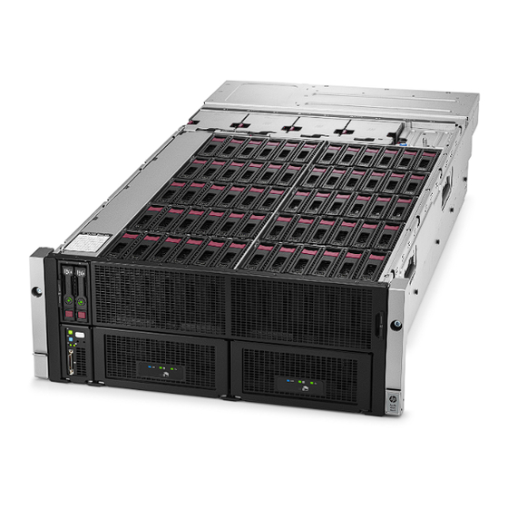
HPE Apollo 4510 Gen9 Chassis
Setup and Installation Guide
Abstract
This document contains setup, installation, and configuration information for the HPE Apollo 4510 Gen9 Chassis. This document is for the
person who installs, administers, and troubleshoots servers and storage systems. Hewlett Packard Enterprise assumes you are qualified in
the servicing of computer equipment and trained in recognizing hazards in products with hazardous energy levels.
Part Number: 819250-004
November 2016
Edition: 5
Advertisement
Table of Contents
Troubleshooting

Subscribe to Our Youtube Channel
Related Manuals for HP apollo 4510 gen9


Summary of Contents for HP apollo 4510 gen9
- Page 1 Setup and Installation Guide Abstract This document contains setup, installation, and configuration information for the HPE Apollo 4510 Gen9 Chassis. This document is for the person who installs, administers, and troubleshoots servers and storage systems. Hewlett Packard Enterprise assumes you are qualified in the servicing of computer equipment and trained in recognizing hazards in products with hazardous energy levels.
- Page 2 © Copyright 2015, 2016 Hewlett Packard Enterprise Development LP The information contained herein is subject to change without notice. The only warranties for Hewlett Packard Enterprise products and services are set forth in the express warranty statements accompanying such products and services. Nothing herein should be construed as constituting an additional warranty.
-
Page 3: Table Of Contents
Contents Planning the installation ..........................5 Verifying the pallet contents ............................. 5 Warnings and cautions ............................. 6 Space and airflow requirements ..........................6 Temperature requirements ............................7 Power requirements ..............................7 Grounding requirements ............................8 Identifying components and LEDs ......................9 Front panel components ............................ - Page 4 Symbols on equipment ..........................44 Troubleshooting resources ............................. 45 Warranty and regulatory information ....................... 46 Warranty information .............................. 46 Regulatory information ............................46 Safety and regulatory compliance ....................... 46 Belarus Kazakhstan Russia marking ......................46 Turkey RoHS material content declaration ....................47 Ukraine RoHS material content declaration ....................
-
Page 5: Planning The Installation
I/O module Access panel Management module System fans (5) Drives* Drive blank HPE Apollo 4510 Gen9 Chassis Server Power supply* Power supply blank Rack rails and cable management arm** * The quantity depends on the configuration ordered. Planning the installation 5... -
Page 6: Warnings And Cautions
** Not shown Warnings and cautions WARNING: To reduce the risk of personal injury or damage to equipment, heed all warnings and cautions throughout the installation instructions. WARNING: To reduce the risk of personal injury or damage to the equipment, be sure that: •... -
Page 7: Temperature Requirements
• Leave a minimum clearance of 121.9 cm (48.0 in) in front of the rack and between rows of racks. • Leave a minimum clearance of 76.2 cm (30.0 in) in back of the rack for a single row of racks or after the final row of racks. -
Page 8: Grounding Requirements
Grounding requirements This equipment must be grounded properly for proper operation and safety. In the United States, you must install the equipment in accordance with NFPA 70, 1999 Edition (National Electric Code), Article 250, as well as any local and regional building codes. In Canada, you must install the equipment in accordance with Canadian Standards Association, CSA C22.1, Canadian Electrical Code. -
Page 9: Identifying Components And Leds
Identifying components and LEDs Front panel components Item Description Server bay Server bay LFF drives Chassis serial label pull tab Quick-release levers (2) Storage LED display Storage display LEDs Item LED description LED state UID LED Off = Normal operating mode Solid blue = One or more drives is in locate mode. -
Page 10: Server Front Panel Components
Item LED description LED state Drive health LED Off = No drives are configured. Solid green = One or more drives are members of a logical drive. Flashing green = One or more drives are rebuilding or performing a RAID migration, stripe size migration, capacity expansion, logical drive extension, or erasing. -
Page 11: Server Front Panel Leds And Buttons
Server front panel LEDs and buttons Item Description Status Power On/Standby button Solid green = System on and system power LED Flashing green (1 Hz/cycle per sec) = Performing power on sequence Solid amber = System in standby Off = No power present UID button/LED Solid blue = Activated Flashing blue:... -
Page 12: Rear Panel Components
Rear panel components Item Description Rear LFF drive cage blank I/O module Power supply bay 4 Power supply bay 3 Power supply bay 2 Power supply bay 1 Management module Power supply LEDs The power supply LED is located on each power supply. LED Status Description System is off or power supply has failed. -
Page 13: Management Module Components
Management module components Item Description HPE APM connector HPE iLO connector Management module thumbscrew Reserved Management module release lever Management module LEDs Item Description Management module UID LED Management module health LED iLO link LED iLO activity LED Identifying components and LEDs 13... -
Page 14: I/O Module Components
I/O module components Item Description PCIe expansion slot 4 PCIe expansion slot 3 PCIe expansion slot 2 PCIe expansion slot 1 FlexibleLOM slot NIC 2 NIC 1 The FlexibleLOM slot is not available on the I/O module with the x16 PCIe riser option. I/O module LEDs Item Description... -
Page 15: Pcie Slot Definitions (Standard I/O Module)
Item Description NIC 2 link LED PCIe slot definitions (standard I/O module) Item Description PCIe expansion slot 4* — PCIe3 x8 (8, 4, 2, 1)** PCIe expansion slot 3* — PCIe3 x8 (8, 4, 2, 1)** PCIe expansion slot 2* — PCIe3 x8 (8, 4, 2, 1) PCIe expansion slot 1* —... -
Page 16: Pcie Slot Definitions (I/O Module With X16 Riser Option)
PCIe slot definitions (I/O module with x16 riser option) Item Description PCIe expansion slot 4* — PCIe3 x8 (8, 4, 2, 1)** PCIe expansion slot 3* — PCIe3 x8 (8, 4, 2, 1)** PCIe expansion slot 2* — PCIe3 x16 (16, 8, 4, 2, 1) PCIe expansion slot 1* —... -
Page 17: Hpe Smart Array P440 Controller Port Identification
HPE Smart Array P440 Controller port identification Item Description Cache module Cache module cable connector Internal SAS port 1I HPE Smart Array P840 Controller port identification Item Description Cache module cable connector Cache module Internal SAS port 1I Internal SAS port 2I Identifying components and LEDs 17... -
Page 18: Hpe H240 Smart Host Bus Adapter Port Identification
HPE H240 Smart Host Bus Adapter port identification Item Description Port 2i Port 1i LFF drive bay numbering The drives are numbered 1-60 for each server installed in the chassis. The first digit in the illustration represents the server associated with the drive and the second set of digits represent the drive bay number. -
Page 19: Lff Drive Led Definitions
LFF drive LED definitions Item Definition Fault/UID (amber/blue) Online/Activity (green) Online/Activity Fault/UID LED Definition LED (green) (amber/blue) Alternating One or more of the following conditions exist: On, off, or amber and blue flashing • The drive has failed. • A predictive failure alert has been received for this drive. •... -
Page 20: Optional 8 Lff Drive Cage Bay Numbering
Optional 8 LFF drive cage bay numbering Identifying components and LEDs 20... -
Page 21: Installing The Chassis
Installing the chassis Installation overview To set up and install the chassis: Set up and install the rack. For more information, see the documentation that ships with the rack. Disassemble the chassis ("Disassembling the chassis" on page 21). Install the chassis into the rack (on page 25). Install the system components into the chassis (on page 28). - Page 22 Management module I/O module CAUTION: To avoid damage to the server, always support the bottom of the server when removing it from the chassis. Installing the chassis 22...
- Page 23 Server CAUTION: To avoid damage to the device, do not use the removal handle to carry it. Remove the access panel. Installing the chassis 23...
- Page 24 Remove all LFF drives. System fans (bays 1 through 4) In bay 5, open the fan bay door. Installing the chassis 24...
-
Page 25: Install The Chassis Into The Rack
CAUTION: Hewlett Packard Enterprise has not tested or validated the Apollo 4510 Gen9 Chassis with any third-party racks. Before installing the Apollo 4510 Gen9 Chassis in a third-party rack, be sure to properly scope the limitations of the rack. Before proceeding with the installation, consider the following: •... - Page 26 the rack with each subsequent chassis. Plan the rack installation carefully because it is difficult to change the location of components after they are installed. WARNING: To reduce the risk of personal injury or damage to the equipment, be sure that: •...
- Page 27 Fully extend the rails by pressing the push tabs and extending the rails until the rails click two times. CAUTION: Be sure to keep the product parallel to the floor when installing the chassis. Tilting the product up or down could result in damage to the rails. Installing the chassis 27...
-
Page 28: Install The System Components Into The Chassis
Install the chassis into the J-slot on the rails, and then pull it forward. Press the Push tabs on each rail, and then slide the chassis into the rack. When the chassis stops midway, press the push tabs on each rail to release the chassis and slide it fully into the rack. CAUTION: Press and hold the "Push"... -
Page 29: Installing A Hot-Plug Drive
CAUTION: To prevent improper cooling and thermal damage, do not operate the server unless all bays are populated with either a component or a blank. To install the component: Prepare the server for installation. Install the server. When seated properly, the server will be flush with the front of the chassis and the release lever will close completely without resistance. -
Page 30: Installing A Flex Slot Power Supply
Prepare the low-profile LFF hot-plug drive for installation. Install the LFF hot-plug drive in the chassis. Determine the status of the drives using the drive LEDs located on the storage display LEDs (on page 9). To configure arrays, see the HPE Smart Storage Administrator User Guide on the Hewlett Packard Enterprise website (http://www.hpe.com/info/smartstorage/docs). -
Page 31: Installing The System Fan
Install the component as indicated. Installing the system fan To install the component: To install a fan in bay 5, open the fan door. For all other fans, proceed to step 2. Push in on the tabs, and then insert the system fan into the chassis. IMPORTANT: Use the tabs to insert the system fan into the chassis. -
Page 32: Installing A Management Module
Installing a management module Install the component as indicated. Installing the chassis 32... -
Page 33: Installing The Expansion Board
Installing the expansion board Remove the I/O module. Remove the I/O module access panel. Installing the chassis 33... -
Page 34: Installing An I/O Module
Remove the PCIe blank from the expansion slot. Install a supported expansion board option in one of the PCIe expansion slots. Only slots 3 and 4 support HPE Smart Array Controllers. If installing an expansion board option in an I/O module with the x16 riser option, be sure to install the x16 expansion board in PCIe slot 2. -
Page 35: Hpe Smart Storage Battery Option
Install the component as indicated. HPE Smart Storage Battery option The HPE Apollo 4500 system with its centralized HPE Smart Storage Battery supports up to two HPE Smart Array controllers per node. To install the component: Install the Smart Storage Battery. Installing the chassis 35... - Page 36 Connect the Smart Storage Battery cable to the Smart Storage Battery connector. Installing the chassis 36...
-
Page 37: Cabling And Powering Up The Chassis
Cabling and powering up the chassis Cabling the chassis After all system hardware is installed, cable the components. WARNING: To reduce the risk of electric shock or injury due to high-current electrical energy, be sure that all power is completely disconnected at the source before beginning any power connections to the power bus bars or power bus box. - Page 38 To install the component: Install the rack rail brace. Align and install the cable management arm. Cabling and powering up the chassis 38...
-
Page 39: Converting The Cable Management Arm For Opposite Side Mounting
Press the latch and slide the cable management arm into place. Converting the cable management arm for opposite side mounting The cable management arm is designed for ambidextrous implementation. You can convert the arm for right-hand swing. IMPORTANT: When converting the cable arm, always be sure to orient the arm with the cable trough facing upward. -
Page 40: I/O Module Option Cabling
Move the cable management arm to the right rack rail and align the tab for opposite side mounting. Align and install the cable management arm on the right rack rail. I/O module option cabling The HPE Apollo 4500 system with its centralized HPE Smart Storage Battery supports up to two HPE Smart Array controllers per node. -
Page 41: Hpe Smart Array P440 Controller Cabling
HPE Smart Array P440 Controller cabling The HPE Apollo 4510 Gen9 Chassis supports single and dual installation for the HPE Smart Array P440 Controller. • Single-board option • Dual-board option Cabling and powering up the chassis 41... -
Page 42: Hpe Smart Array P840 Controller Cabling
The HPE Apollo 4510 Gen9 Chassis supports single installation for the HPE Smart Array P840 Controller. HPE H240 Smart Host Bus Adapter cabling The HPE Apollo 4510 Gen9 Chassis supports single and dual installation for the HPE H240 Smart Host Bus Adapter. -
Page 43: Powering Up The System
• Dual-board option Powering up the system Connect the power cables to the power supplies. Connect the power cables to the power source (UPS or wall outlet) or to an installed PDU. Press the Power On/Standby button on the server. Hot-plug power supply calculations For hot-plug power supply specifications and calculators to determine electrical and heat loading for the server, see the Hewlett Packard Enterprise Power Advisor website... -
Page 44: Troubleshooting
Troubleshooting Important safety information Familiarize yourself with the safety information in the following sections before troubleshooting the server. Important safety information Before servicing this product, read the Important Safety Information document provided with the server. Symbols on equipment The following symbols may be placed on equipment to indicate the presence of potentially hazardous conditions. -
Page 45: Troubleshooting Resources
Troubleshooting resources Troubleshooting resources are available for HPE ProLiant Gen9 servers in the following documents: • The HPE ProLiant Gen9 Troubleshooting Guide, Volume I: Troubleshooting provides procedures for resolving common problems and comprehensive courses of action for fault isolation and identification, issue resolution, and software maintenance on ProLiant servers and server blades. -
Page 46: Warranty And Regulatory Information
Warranty and regulatory information Warranty information HPE ProLiant and x86 Servers and Options (http://www.hpe.com/support/ProLiantServers-Warranties) HPE Enterprise Servers (http://www.hpe.com/support/EnterpriseServers-Warranties) HPE Storage Products (http://www.hpe.com/support/Storage-Warranties) HPE Networking Products (http://www.hpe.com/support/Networking-Warranties) Regulatory information Safety and regulatory compliance For important safety, environmental, and regulatory information, see Safety and Compliance Information for Server, Storage, Power, Networking, and Rack Products, available at the Hewlett Packard Enterprise website (http://www.hpe.com/support/Safety-Compliance-EnterpriseProducts). -
Page 47: Turkey Rohs Material Content Declaration
Local representative information Kazakh: • Russia: • Belarus: • Kazakhstan: Manufacturing date: The manufacturing date is defined by the serial number. CCSYWWZZZZ (serial number format for this product) Valid date formats include: • YWW, where Y indicates the year counting from within each new decade, with 2000 as the starting point;... -
Page 48: Specifications
Specifications Environmental specifications Specification Value Temperature range* 10°C to 35°C (50°F to 95°F) Operating -40°C to 70°C (-40°F to 158°F) Shipping Maximum wet bulb temperature 28°C (82.4°F) Relative humidity (noncondensing)** 10% to 90% Operating 5% to 95% Nonoperating * All temperature ratings shown are for sea level. An altitude derating of 1°C per 300 m (1.8°F per 1,000 ft) to 3,048 m (10,000 ft) is applicable. -
Page 49: Hpe 800W Flex Slot -48Vdc Hot-Plug Power Supply
100 to 127 VAC Rated input voltage 200 to 240 VAC 240 VDC for China only 50 Hz to 60 Hz Rated input frequency Not applicable to 240VDC 9.4 A at 100 VAC Rated input current 4.5 A at 200 VAC 3.8 A at 240 VDC for China only 940 W at 100 VAC Maximum rated input power... -
Page 50: Hpe 800W Flex Slot Titanium Plus Hot-Plug Power Supply
• Connect the equipment to a reliably grounded Secondary circuit source. A Secondary circuit has no direct connection to a Primary circuit and derives its power from a transformer, converter, or equivalent isolation device. • The branch circuit overcurrent protection must be rated 27 A. CAUTION: This equipment is designed to permit the connection of the earthed conductor of the DC supply circuit to the earthing conductor at the equipment. -
Page 51: Hpe 1400W Flex Slot Platinum Plus Hot-Plug Power Supply
4.5 A at 200 V AC Rated input current 3.2 A at 277 V AC 2.3 A at 380 VDC 900 W at 200 VAC Maximum rated input power 887 W at 277 VAC 874 W at 380 VDC 3071 at 200 VAC BTUs per hour 3026 at 277 VAC 2982 at 380 VDC... -
Page 52: Environmental Considerations
Environmental considerations Communications interference Hewlett Packard Enterprise system compliance tests are conducted with Hewlett Packard Enterprise supported peripheral devices and shielded cables, such as those received with the system. The system meets interference requirements of all countries in which it is sold. These requirements provide reasonable protection against interference with radio and television communications. - Page 53 • Use heel straps, toe straps, or boot straps at standing workstations. Wear the straps on both feet when standing on conductive floors or dissipating floor mats. • Use conductive field service tools. • Use a portable field service kit with a folding static-dissipating work mat. If you do not have any of the suggested equipment for proper grounding, have an authorized reseller install the part.
-
Page 54: Support And Other Resources
Hewlett Packard Enterprise Support Center More Information on Access to Support Materials page (http://www.hpe.com/support/AccessToSupportMaterials). IMPORTANT: Access to some updates might require product entitlement when accessed through the Hewlett Packard Enterprise Support Center. You must have an HP Passport set up with relevant entitlements. Websites •... -
Page 55: Customer Self Repair
• Subscription Service/Support Alerts (http://www.hpe.com/support/e-updates) • Software Depot (http://www.hpe.com/support/softwaredepot) • Customer Self Repair (http://www.hpe.com/support/selfrepair) • Insight Remote Support (http://www.hpe.com/info/insightremotesupport/docs) Customer Self Repair Hewlett Packard Enterprise products are designed with many Customer Self Repair (CSR) parts to minimize repair time and allow for greater flexibility in performing defective parts replacement. If during the diagnosis period Hewlett Packard Enterprise (or Hewlett Packard Enterprise service providers or service partners) identifies that the repair can be accomplished by the use of a CSR part, Hewlett Packard Enterprise will ship that part directly to you for replacement. - Page 56 REMARQUE: Certaines pièces Hewlett Packard Enterprise ne sont pas conçues pour permettre au client d'effectuer lui-même la réparation. Pour que la garantie puisse s'appliquer, Hewlett Packard Enterprise exige que le remplacement de la pièce soit effectué par un Mainteneur Agréé. Ces pièces sont identifiées par la mention "Non"...
- Page 57 Customer Self Repair Hewlett Packard Enterprise Produkte enthalten viele CSR-Teile (Customer Self Repair), um Reparaturzeiten zu minimieren und höhere Flexibilität beim Austausch defekter Bauteile zu ermöglichen. Wenn Hewlett Packard Enterprise (oder ein Hewlett Packard Enterprise Servicepartner) bei der Diagnose feststellt, dass das Produkt mithilfe eines CSR-Teils repariert werden kann, sendet Ihnen Hewlett Packard Enterprise dieses Bauteil zum Austausch direkt zu.
- Page 58 NOTA: Algunos componentes de Hewlett Packard Enterprise no están diseñados para que puedan ser reparados por el usuario. Para que el usuario haga valer su garantía, Hewlett Packard Enterprise pone como condición que un proveedor de servicios autorizado realice la sustitución de estos componentes. Dichos componentes se identifican con la palabra "No"...
- Page 59 onderdeel en kiest Hewlett Packard Enterprise zelf welke koerier/transportonderneming hiervoor wordt gebruikt. Neem contact op met een Service Partner voor meer informatie over het Customer Self Repair programma van Hewlett Packard Enterprise. Informatie over Service Partners vindt u op de Hewlett Packard Enterprise website (http://www.hpe.com/support/selfrepair).
- Page 60 Support and other resources 60...
- Page 61 Support and other resources 61...
-
Page 62: Remote Support
Remote support Remote support is available with supported devices as part of your warranty or contractual support agreement. It provides intelligent event diagnosis, and automatic, secure submission of hardware event notifications to Hewlett Packard Enterprise, which will initiate a fast and accurate resolution based on your product's service level. -
Page 63: Acronyms And Abbreviations
Acronyms and abbreviations alternating current advanced power management Canadian Standards Association Customer Self Repair electrostatic discharge International Electrotechnical Commission Integrated Lights-Out large form factor LAN on Motherboard PCIe Peripheral Component Interconnect Express power distribution unit TMRA recommended ambient operating temperature unit identification Acronyms and abbreviations 63... - Page 64 uninterruptible power system universal serial bus Acronyms and abbreviations 64...
-
Page 65: Documentation Feedback
Documentation feedback Hewlett Packard Enterprise is committed to providing documentation that meets your needs. To help us improve the documentation, send any errors, suggestions, or comments to Documentation Feedback (mailto:docsfeedback@hpe.com). When submitting your feedback, include the document title, part number, edition, and publication date located on the front cover of the document. For online help content, include the product name, product version, help edition, and publication date located on the legal notices page. -
Page 66: Index
Index drive bays 9, 10, 18, 20 airflow requirements 6 authorized reseller 52, 54 electrical 52 electrical grounding requirements 8 electrostatic discharge 52 enclosure, disassembling 21 batteries, replacing 35 environmental considerations 52 battery replacement notice 46 environmental specifications 48, 52 battery warranty 46 error messages 45 before you contact Hewlett Packard Enterprise 54... - Page 67 installing components 28 rear panel components 12 installing fans 31 regulatory compliance identification numbers 44, 46 regulatory compliance information 46 regulatory compliance notices 46, 47 regulatory information 46 Japanese notice 46 requirements, airflow 6 requirements, electrical grounding 8 requirements, minimum 7, 8 requirements, power 7 LED identification 9 requirements, space 6...
- Page 68 warranty 46 warranty information 46 website, Hewlett Packard Enterprise 54 Index 68...
Need help?
Do you have a question about the apollo 4510 gen9 and is the answer not in the manual?
Questions and answers