Table of Contents
Advertisement
Quick Links
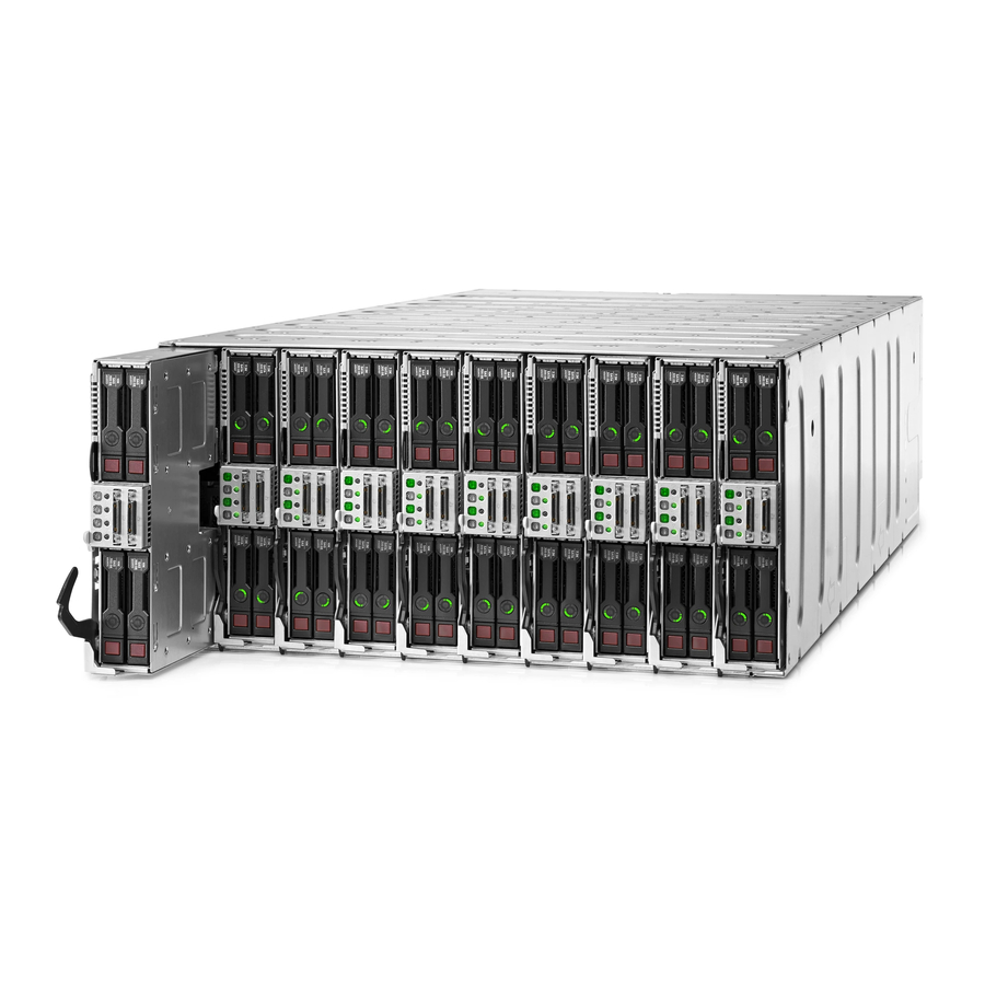
HP Apollo a6000 Chassis
Setup and Installation Guide
Abstract
This document contains setup, installation, and configuration information for the HP Apollo a6000 Chassis. This document is for the person who
installs, administers, and troubleshoots the system. HP assumes you are qualified in the servicing of computer equipment and trained in recognizing
hazards in products with hazardous energy levels.
Part Number: 752046-001
June 2014
Edition: 1
Advertisement
Table of Contents

Subscribe to Our Youtube Channel
Related Manuals for HP Apollo a6000


Summary of Contents for HP Apollo a6000
- Page 1 Abstract This document contains setup, installation, and configuration information for the HP Apollo a6000 Chassis. This document is for the person who installs, administers, and troubleshoots the system. HP assumes you are qualified in the servicing of computer equipment and trained in recognizing hazards in products with hazardous energy levels.
- Page 2 © Copyright 2014 Hewlett-Packard Development Company, L.P. The information contained herein is subject to change without notice. The only warranties for HP products and services are set forth in the express warranty statements accompanying such products and services. Nothing herein should be construed as constituting an additional warranty. HP shall not be liable for technical or editorial errors or omissions contained herein.
-
Page 3: Table Of Contents
Cabling ............................. 27 Cabling overview ............................27 Connecting the chassis to a power shelf ....................... 27 Example configurations ........................30 Connecting the optional HP APM module ..................... 31 Connecting power cables and applying power to the chassis ................. 32 Contents 3... - Page 4 Three-phase power (North America/Japan) ..................41 Three-phase power (International) ...................... 42 Hot-plug power supply calculations ......................42 Support and other resources ......................43 Before you contact HP ..........................43 HP contact information ..........................43 Acronyms and abbreviations ......................44 Documentation feedback ......................45 Index ............................
-
Page 5: Planning The Installation
Planning the installation Safety and regulatory compliance For safety, environmental, and regulatory information, see Safety and Compliance Information for Server, Storage, Power, Networking, and Rack Products, available at the HP website (http://www.hp.com/support/Safety-Compliance-EnterpriseProducts). Site requirements Select an installation site that meets the detailed installation site requirements described in the site planning guide on the Documentation CD and on the HP website (http://www.hp.com). -
Page 6: Hot-Plug Power Supply Calculations
To install, configure, and access HP APM, see the HP Advanced Power Manager User Guide on the HP website (http://www.hp.com/support/APM_UG_en). Hot-plug power supply calculations For more information on the hot-plug power supply and calculators to determine server power consumption in various system configurations, see the HP Power Advisor website (http://www.hp.com/go/hppoweradvisor). -
Page 7: Space And Airflow Requirements
HP servers draw in cool air through the front door and expel warm air through the rear door. Therefore, the front and rear rack doors must be adequately ventilated to allow ambient room air to enter the cabinet, and the rear door must be adequately ventilated to allow the warm air to escape from the cabinet. -
Page 8: Temperature Requirements
CAUTION: If a third-party rack is used, observe the following additional requirements to ensure adequate airflow and to prevent damage to the equipment: Front and rear doors—If the 42U rack includes closing front and rear doors, you must allow • 5,350 sq cm (830 sq in) of holes evenly distributed from top to bottom to permit adequate airflow (equivalent to the required 64 percent open area for ventilation). -
Page 9: Identifying Components And Leds
Power cage (Left) HP Apollo a6000 5U Chassis 5U Rail kit** * The quantity depends on the configuration ordered. ** Not shown The following documents also ship with the HP Apollo a6000 5U Chassis: • Start Here for Important Setup Information •... -
Page 10: Server Tray Bay Numbering
Server tray bay numbering Rear panel components Item Description I/O modules (10) Fan assemblies (5) Power cage (Right) Management module Power cage (Left) Identifying components and LEDs 10... -
Page 11: Fan Assembly Bay Numbering
Fan assembly bay numbering The chassis has five fan assemblies located in the rear of the chassis. The following figure identifies the fan assemblies by device number. Fan LED Status Description The fan is working or the power is off. The fan has failed. -
Page 12: Management Module Components
Management module components Item Description Label Management connector MGMT Reserved SLAPM1 HP APM connector SLAPM2 Network 1 connector — Network 2 connector — IMPORTANT: Do not connect both iLO ports to the network at the same time. Only one iLO port can be connected to the network, while the other iLO port can be used only as a connection to a second enclosure. -
Page 13: I/O Module Bay Numbering
Power shelf rear panel components NOTE: The single-phase power shelf is shown below. A three-phase power shelf is also available. Item Description Power management connectors (6) HP APM module connector (PDM) AC input module power connectors (6) Identifying components and LEDs 13... -
Page 14: Power Supply Leds
Power supply LEDs Power LED 1 Fault LED 2 Condition (green) (amber) No AC power to the power supply Normal Power supply failure Identifying components and LEDs 14... -
Page 15: Installing The Chassis
Installing the rack rails The chassis requires installation in a rack. To install the rack rails, see the HP Apollo a6000 5U Chassis Rail in HP Racks Installation Instructions that ship with the HP Apollo a6000 5U Chassis Rail kit. - Page 16 HP has not tested or validated the HP Apollo a6000 5U Chassis with any third-party racks. Before installing the HP Apollo a6000 5U Chassis in a third-party rack, be sure to properly scope the limitations of the rack. Before proceeding with the installation, consider the following: •...
-
Page 17: Installing The System Components
For component-specific replacement information, see the HP Apollo a6000 5U Chassis Maintenance and Service Guide or the server-specific user and maintenance guides on the HP website (http://www.hp.com/go/docs). -
Page 18: Installing A Server
CAUTION: To prevent improper cooling and thermal damage, do not operate the chassis unless all bays are populated with a component or a blank. Install the component as indicated. Installing a server CAUTION: To prevent improper cooling and thermal damage, do not operate the chassis unless all bays are populated with a component or a blank. -
Page 19: Installing An I/O Module
Install the server. When seated properly, the server will be flush with the front of the chassis and the release lever will close completely without resistance. Installing an I/O module Install the component as indicated. Installing the chassis 19... -
Page 20: Installing The Fans
Installing the fans Install the component as indicated. Installing a power cage CAUTION: To prevent damage to the component, power down the chassis and disconnect all power cords before removing or installing the component. To install the component: Remove the power cage cover. Installing the chassis 20... - Page 21 Install the power cables in the power cage. Install the power cage cover. Install the power cage. Insert the power cage into the correct power cage bay. Close the release lever. Installing the chassis 21...
-
Page 22: Installing The Management Module
Tighten the screw to secure the power cage to the chassis. Installing the management module IMPORTANT: Always complete the installation of both power cages before installing the management module. Install the component as indicated. Installing the power shelf CAUTION: To prevent damage to the component, power down the chassis and disconnect all power cords before removing or installing the component. - Page 23 Install the power shelf rack rails into the rack. For more information, see the HP Apollo 6000 Power Shelf Rack Rail in HP Racks Installation Instructions. Install the power shelf. Secure the power shelf to the rack. Installing the chassis 23...
- Page 24 Install the power supplies into the power shelf, if needed. NOTE: If additional clearance is required to install power cables, loosen the thumb screw on either side of the shelf and slide the shelf out while installing the cables. Use caution to avoid bending the shelf.
- Page 25 Slide the cables toward the center, allowing them to straighten and hang from the rear of the power shelf. Install the cable guard. NOTE: Cables are removed for clarity. Installing the chassis 25...
- Page 26 Install the power supply vent cover to protect the power supply vents. Installing the chassis 26...
-
Page 27: Cabling
After the hardware is installed, complete the following cabling procedures: Connecting the chassis to a power shelf (on page 27). Connecting the optional HP APM module (on page 31). Connecting power cables and applying power to the chassis (on page 32). - Page 28 • Connecting three chassis to one power shelf Cabling 28...
- Page 29 • Connecting four chassis to one power shelf Cabling 29...
-
Page 30: Example Configurations
Configuration examples can be calculated using the HP Power Advisor Tool (http://www.hp.com/go/hppoweradvisor). This tool is designed for facilities planning purposes only. Values obtained from the tool are based on worst case loads. Whenever possible, HP recommends using actual measurements in configuration planning. Measurements must be made with the intended configuration, application loading, and ambient environment. -
Page 31: Connecting The Optional Hp Apm Module
Connecting the optional HP APM module Connect the HP APM to the network (green cables). Connect the HP APM to the chassis (red cables). Connect the HP APM to the power shelf (blue cable). Cabling 31... -
Page 32: Connecting Power Cables And Applying Power To The Chassis
Connecting power cables and applying power to the chassis Connect the DC power cable to the power shelf. Connect the AC power cables to the power source (UPS or wall outlet) or to an installed PDU. Cabling 32... -
Page 33: Configuring The System
Configuring the system Power capping The HP ProLiant XL family of products provides a power capping feature that operates at the server enclosure level. The capping feature can be activated with PPIC.EXE, a stand-alone utility that runs in the environment of one of the resident servers in the chassis to be power capped. - Page 34 (http://www.hp.com/support/PPIC_UG_en). • HP Advanced Power Manager HP APM is a rack level device that can control power caps for all enclosures in the rack. For more information, see the HP Advanced Power Manager User Guide on the HP website (http://www.hp.com/support/APM_UG_en).
- Page 35 If NONE is specified instead of a cap wattage value, then HP APM removes all (or the specified zone) of the power caps. To remove baseline data from the EEPROM and to remove the power cap setting, enter the following command: >SET POWER BASELINE NONE...
-
Page 36: Troubleshooting
Troubleshooting Troubleshooting resources The HP ProLiant Gen8 Troubleshooting Guide, Volume I: Troubleshooting provides procedures for resolving common problems and comprehensive courses of action for fault isolation and identification, issue resolution, and software maintenance on ProLiant servers and server blades. To view the guide, select a language: •... -
Page 37: Electrostatic Discharge
Electrostatic discharge Preventing electrostatic discharge To prevent damaging the system, be aware of the precautions you need to follow when setting up the system or handling parts. A discharge of static electricity from a finger or other conductor may damage system boards or other static-sensitive devices. -
Page 38: Regulatory Information
These requirements provide reasonable protection against interference with radio and television communications. Installing and using the system in strict accordance with HP instructions minimizes the chances that the system might cause radio or television interference. However, HP does not guarantee that the system does not interfere with radio and television reception. - Page 39 • Ensure that all cable connector screws are firmly tightened. • Use only HP supported peripheral devices. • Before system operation, ensure that all panels and cover plates are in place and secure. Regulatory information 39...
-
Page 40: Specifications
Specifications Chassis environmental specifications Specification Value — Temperature range* 10°C to 35°C (50°F to 95°F) Operating -30°C to 60°C (-22°F to Non-operating 140°F) — Maximum Wet bulb temperature 28ºC (82.4ºF) Operating 38.7ºC (101.7ºF) Non-operating Relative humidity (non-condensing)** — 10% to 90% Operating 5% to 95% Non-operating... -
Page 41: Power Specifications
Power specifications The power requirements for the HP Apollo a6000 5U Chassis are met by the following components: • HP 2450W Platinum Hot Plug Redundant Power Supply • HP 2650W Platinum Hot Plug Redundant Power Supply • HP Apollo 6000 Power Shelf •... -
Page 42: Three-Phase Power (International)
WYE wall plug configuration. Input AC modules are configured to provide 220 VAC to 240 VAC to the power supplies in this system. Hot-plug power supply calculations For hot-plug power supply specifications and calculators to determine electrical and heat loading for the server, see the HP Power Advisor website (http://www.hp.com/go/hppoweradvisor). Specifications 42... -
Page 43: Support And Other Resources
Active Health System log (HP ProLiant Gen8 or later products) Download and have available an Active Health System log for 3 days before the failure was detected. For more information, see the HP iLO 4 User Guide or HP Intelligent Provisioning User Guide on the HP website (http://www.hp.com/go/ilo/docs). -
Page 44: Acronyms And Abbreviations
HP APM HP Advanced Power Manager Integrated Lights-Out power distribution unit PPIC HP ProLiant Power Interface Control Utility TMRA recommended ambient operating temperature unit identification uninterruptible power system Acronyms and abbreviations 44... -
Page 45: Documentation Feedback
Documentation feedback HP is committed to providing documentation that meets your needs. To help us improve the documentation, send any errors, suggestions, or comments to Documentation Feedback (mailto:docsfeedback@hp.com). Include the document title and part number, version number, or the URL when submitting your feedback. -
Page 46: Index
33 Configuring the system 33 help resources 43 connecting to the network 27 HP Advanced Power Manager (HP APM) 5 contact information 43 HP contact information 43 contacting HP 43 HP Management Packs 1.1 for MOM 2005,... - Page 47 power specifications 41, 42 power supply 6 installation overview 5, 15 power supply calculations 6 installation, chassis 15 powering up 32 installation, fans 20 PPIC utility 34 installation, rack rails 15 preparation procedures 5 installing the chassis 15 problem diagnosis 36 installing the rack rails 15 internal cables 27 rack rails, installation 15...
- Page 48 Turkey RoHS material content declaration 38 Ukraine RoHS material content declaration 38 uninterruptible power supply (UPS) 5 unpacking the components 15 UPS (uninterruptible power supply) 5 warnings 6 warranty 38 warranty information 38 website, HP 43 weight 40 Index 48...
Need help?
Do you have a question about the Apollo a6000 and is the answer not in the manual?
Questions and answers