Table of Contents
Advertisement
Quick Links
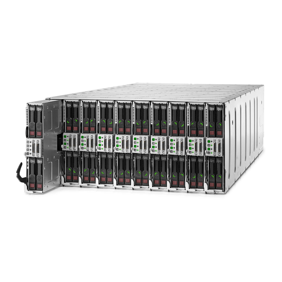
HPE Apollo a6000 Chassis
Setup and Installation Guide
Abstract
This document contains setup, installation, and configuration information for the HPE Apollo a6000 Chassis. This document is for the
person who installs, administers, and troubleshoots the system. Hewlett Packard Enterprise assumes you are qualified in the servicing of
computer equipment and trained in recognizing hazards in products with hazardous energy levels.
Part Number: 752046-004
September 2016
Edition: 4
Advertisement
Table of Contents

Related Manuals for HP Apollo a6000


Summary of Contents for HP Apollo a6000
- Page 1 Setup and Installation Guide Abstract This document contains setup, installation, and configuration information for the HPE Apollo a6000 Chassis. This document is for the person who installs, administers, and troubleshoots the system. Hewlett Packard Enterprise assumes you are qualified in the servicing of computer equipment and trained in recognizing hazards in products with hazardous energy levels.
- Page 2 © Copyright 2014, 2016 Hewlett Packard Enterprise Development LP The information contained herein is subject to change without notice. The only warranties for Hewlett Packard Enterprise products and services are set forth in the express warranty statements accompanying such products and services. Nothing herein should be construed as constituting an additional warranty.
-
Page 3: Table Of Contents
Contents Planning the installation ..........................5 Safety and regulatory compliance ..........................5 Configuration guidelines ............................5 Determine power and cooling configurations ......................5 Power requirements ............................5 HPE Apollo Platform Manager........................5 Hot-plug power supply calculations ....................... 5 Compiling the documentation ........................... 6 Warnings and cautions ............................. - Page 4 Troubleshooting ............................36 Troubleshooting resources ............................. 36 Electrostatic discharge ..........................37 Preventing electrostatic discharge ......................... 37 Grounding methods to prevent electrostatic discharge ..................37 Warranty and regulatory information ....................... 38 Warranty information .............................. 38 Regulatory information ............................38 Safety and regulatory compliance ....................... 38 Belarus Kazakhstan Russia marking ......................
-
Page 5: Planning The Installation
Planning the installation Safety and regulatory compliance For important safety, environmental, and regulatory information, see Safety and Compliance Information for Server, Storage, Power, Networking, and Rack Products, available at the Hewlett Packard Enterprise website (http://www.hpe.com/support/Safety-Compliance-EnterpriseProducts). Configuration guidelines To meet thermal requirements, always do the following: •... -
Page 6: Compiling The Documentation
• HPE Apollo a6000 Chassis Quick Setup Instructions • HPE Apollo a6000 Chassis Rail Kit for HPE and Third Party Racks Installation Instructions • HPE Power Shelf Rack Rail Kit for HPE and Third Party Racks Installation Instructions These documents provide required important safety information and decision-making steps for configuration. -
Page 7: Space And Airflow Requirements
CAUTION: Always be sure that equipment is properly grounded and that you follow proper grounding procedures before beginning any installation procedure. Improper grounding can result in ESD damage to electronic components. For more information, refer to "Electrostatic discharge (on page 37)." CAUTION: When performing non-hot-plug operations, you must power down the server and/or the system. -
Page 8: Grounding Requirements
The operating temperature inside the rack is always higher than the room temperature and is dependent on the configuration of equipment in the rack. Check the TMRA for each piece of equipment before installation. CAUTION: To reduce the risk of damage to the equipment when installing third-party options: •... -
Page 9: Identifying Components And Leds
Fan assembly (5) I/O module Power cage (right) Management module Power cage (left) Power management cable** Apollo a6000 Chassis Rail kit** Service tray* ** * The quantity depends on the configuration ordered. ** Not shown Identifying components and LEDs 9... -
Page 10: Server Tray Bay Numbering
Server tray bay numbering Rear panel components Item Description I/O modules (10) Fan assemblies (5) Power cage (Right) Management module Power cage (Left) Identifying components and LEDs 10... -
Page 11: Fan Assembly Bay Numbering
Fan assembly bay numbering The chassis has five fan assemblies located in the rear of the chassis. The following figure identifies the fan assemblies by device number. Fan LED Status Description The fan is working or the power is off. The fan has failed. -
Page 12: Management Module Components
Having both ports connected at the same time results in a loopback condition. IMPORTANT: If you have an APM connected to an Apollo a6000 Chassis, do not connect the iLO port of the APM and the iLO port of the enclosure to the network at the same time. Having both ports connected at the same time results in a loopback condition. -
Page 13: Management Module Leds And Buttons
Management module LEDs and buttons Item Description UID LED iLO network 1 link LED iLO network 1 activity LED iLO network 2 link LED iLO network 2 activity LED I/O module bay numbering I/O modules are specific to each server and are installed in the rear of the chassis. The chassis has ten I/O module bays located in the rear of the chassis. -
Page 14: Power Supply Leds
Item Description Power management connectors (6) APM module connector (PDM) AC input module power connectors (6) Power supply LEDs Power LED 1 Fault LED 2 Condition (green) (amber) No AC power to the power supply Normal Power supply failure Identifying components and LEDs 14... -
Page 15: Installing The Chassis
Apollo a6000 Chassis Rail in HPE Racks Installation Instructions. Installing the rack rails The chassis requires installation in a rack. To install the rack rails, see the Apollo a6000 Chassis Rail in HPE Racks Installation Instructions on the Hewlett Packard Enterprise website (http://www.hpe.com/info/Apollo_6000/docs). - Page 16 CAUTION: Hewlett Packard Enterprise has not tested or validated the Apollo a6000 Chassis with any third-party racks. Before installing the Apollo a6000 Chassis in a third-party rack, be sure to properly scope the limitations of the rack. Before proceeding with the installation, consider the following: •...
-
Page 17: Installing The System Components
For component-specific replacement information, see the Apollo a6000 Chassis Maintenance and Service Guide or the server-specific user and maintenance guides on the Hewlett Packard Enterprise website (http://www.hpe.com/info/docs). -
Page 18: Installing A Server
CAUTION: To prevent improper cooling and thermal damage, operate servers only when the open side of the server is enclosed by either another server, a divider, or the chassis wall. CAUTION: To prevent improper cooling and thermal damage, do not operate the chassis unless all bays are populated with a component or a blank. -
Page 19: Installing An I/O Module
To install the component: Prepare the server for installation. Install the server. When seated properly, the server will be flush with the front of the chassis and the release lever will close completely without resistance. Installing an I/O module CAUTION: To prevent electrical damage, always power down the server associated with the I/O module before installing the I/O module. -
Page 20: Installing The Fans
Install the component as indicated. For more information about product features, specifications, options, configurations, and compatibility, see the product QuickSpecs on the Hewlett Packard Enterprise website (http://www.hpe.com/info/qs). For more information about installing the options for your server, see the server user guide on the Hewlett Packard Enterprise website (http://www.hpe.com/info/Apollo_6000/docs). - Page 21 CAUTION: Do not overtighten the screws. Hewlett Packard Enterprise recommends using a torque of only 2-4 in-lb. To install the component: Remove the power cage cover. Install the power cables in the power cage. Installing the chassis 21...
-
Page 22: Installing The Management Module
Install the power cage cover. Install the power cage: Insert the power cage into the correct power cage bay. Close the release lever. Tighten the screw to secure the power cage to the chassis. Installing the management module IMPORTANT: Always complete the installation of both power cages before installing the management module. -
Page 23: Installing The Power Shelf
Install the component as indicated. Installing the power shelf CAUTION: To prevent damage to the component, power down the chassis and disconnect all power cords before removing or installing the component. To install the component: Install the power shelf rack rails into the rack. For more information, see the HPE Power Shelf Rack Rail Kit for HPE and Third Party Racks Installation Instructions. - Page 24 Secure the power shelf to the rack. Install the power supplies into the power shelf, if needed. NOTE: If additional clearance is required to install power cables, loosen the thumb screw on either side of the shelf and slide the shelf out while installing the cables. Use caution to avoid bending the shelf.
- Page 25 Insert the cable through the wide opening on either end of the power shelf, and then connect it to the appropriate connector. Slide the cables toward the center, allowing them to straighten and hang from the rear of the power shelf. Install the cable guard.
- Page 26 Install the power supply vent cover to protect the power supply vents. Installing the chassis 26...
-
Page 27: Cabling
Cabling Cabling requirements The following cables are required for all configurations: • Four DC power cables per chassis. • One power data management cable from the chassis to its power shelf. • A maximum of three chassis can be cabled to a power shelf for N+1 power redundancy. For configurations that include the optional HPE APM module, the following additional cables are required: •... - Page 28 IMPORTANT: When connecting the power management cable to the chassis management module and the power shelf, be sure to install the cable with the plastic tab on the top of the connector. Failure to install the cable properly can result in performance and reporting issues. Connect the power management cable to the power shelf with the cable's plastic tab facing up.
- Page 29 • Connecting three chassis to one power shelf Cable quantity and length are determined by the configuration of components. For more information, see the Hewlett Packard Enterprise Power Advisor website (http://www.hpe.com/info/hpepoweradvisor). Example configurations Configuration examples can be calculated using the HPE Power Advisor Tool (http://www.hpe.com/info/poweradvisor/online).
-
Page 30: Connecting The Chassis To The Top-Of-Rack Switch
Connecting the chassis to the top-of-rack switch Connect the chassis to the top-of-rack switch using one of the following configurations: • Connect one RJ-45 from each chassis to the top-of-rack switch. Cabling 30... -
Page 31: Connecting The Optional Hpe Apm Module
Connecting the optional HPE APM module IMPORTANT: If you have an APM connected to an Apollo a6000 Chassis, do not connect the iLO port of the APM and the iLO port of the enclosure to the network at the same time. Having both ports connected at the same time results in a loopback condition. -
Page 32: Connecting Power Cables And Applying Power To The Chassis
Connect the APM to the power shelf (shown in blue). Connecting power cables and applying power to the chassis Connect the DC power cable to the power shelf. Connect the AC power cables to the power source (UPS or wall outlet) or to an installed PDU. Cabling 32... -
Page 33: Configuring The System
Configuring the system Power capping The HPE ProLiant XL family of products provides a power capping feature that operates at the server enclosure level. The capping feature can be activated with PPIC.EXE, a stand-alone utility that runs in the environment of one of the resident servers in the chassis to be power capped. After a power cap is set for the enclosure, all the resident servers in the enclosure will have the same uniform power cap applied to them until the cap is either modified or canceled. -
Page 34: Configuring A Power Cap
continues until the power feed is brought back online. In this mode, the system is expected to survive an unexpected loss of an entire power feed to half of the power supplies. Configuring a power cap To configure power capping, you can use the following utilities: •... - Page 35 The wattage value, if provided, represents the total wattage to be allocated among all the chassis that are part of the baseline or partial baseline of a zone, if specified. This value is divided by the total maximum wattage established by the baseline to calculate a percentage cap value. This percentage is then multiplied against each chassis maximum wattage value to arrive at an appropriate cap value for that individual chassis.
-
Page 36: Troubleshooting
Troubleshooting Troubleshooting resources The HPE ProLiant Gen9 Troubleshooting Guide, Volume I: Troubleshooting provides procedures for resolving common problems and comprehensive courses of action for fault isolation and identification, issue resolution, and software maintenance on ProLiant servers and server blades. To view the guide, select a language: •... -
Page 37: Electrostatic Discharge
Electrostatic discharge Preventing electrostatic discharge To prevent damaging the system, be aware of the precautions you must follow when setting up the system or handling parts. A discharge of static electricity from a finger or other conductor may damage system boards or other static-sensitive devices. This type of damage may reduce the life expectancy of the device. -
Page 38: Warranty And Regulatory Information
Warranty and regulatory information Warranty information HPE ProLiant and x86 Servers and Options (http://www.hpe.com/support/ProLiantServers-Warranties) HPE Enterprise Servers (http://www.hpe.com/support/EnterpriseServers-Warranties) HPE Storage Products (http://www.hpe.com/support/Storage-Warranties) HPE Networking Products (http://www.hpe.com/support/Networking-Warranties) Regulatory information Safety and regulatory compliance For important safety, environmental, and regulatory information, see Safety and Compliance Information for Server, Storage, Power, Networking, and Rack Products, available at the Hewlett Packard Enterprise website (http://www.hpe.com/support/Safety-Compliance-EnterpriseProducts). -
Page 39: Turkey Rohs Material Content Declaration
Local representative information Kazakh: • Russia: • Belarus: • Kazakhstan: Manufacturing date: The manufacturing date is defined by the serial number. CCSYWWZZZZ (serial number format for this product) Valid date formats include: • YWW, where Y indicates the year counting from within each new decade, with 2000 as the starting point;... -
Page 40: Specifications
Specifications Chassis environmental specifications Specification Value — Temperature range* 10°C to 35°C (50°F to 95°F) Operating -30°C to 60°C (-22°F to Nonoperating 140°F) — Maximum wet bulb temperature 28ºC (82.4ºF) Operating 38.7ºC (101.7ºF) Nonoperating — Relative humidity (non condensing)** 10% to 90% Operating 5% to 95% Nonoperating... -
Page 41: Power Specifications
Power specifications The power requirements for the Apollo a6000 Chassis are met by the following components: • HPE 2450W Platinum Hot Plug Redundant Power Supply • HPE 2650W Platinum Hot Plug Redundant Power Supply • Apollo 6000 Power Shelf •... -
Page 42: Three-Phase Power (International)
2450W Platinum Hot Plug 2650W Platinum Hot Plug Specification Redundant Power Supply Redundant Power Supply 7920 VA 8640 VA Maximum input power per line cord Three-phase power (International) Specification 2450W Platinum Hot Plug 2650W Platinum Hot Plug Redundant Power Supply Redundant Power Supply IEC-309 200/380-V to 240/415-V, IEC-309 200/380-V to 240/415-V,... -
Page 43: Support And Other Resources
Hewlett Packard Enterprise Support Center More Information on Access to Support Materials page (http://www.hpe.com/support/AccessToSupportMaterials). IMPORTANT: Access to some updates might require product entitlement when accessed through the Hewlett Packard Enterprise Support Center. You must have an HP Passport set up with relevant entitlements. Websites •... -
Page 44: Remote Support
Software Depot (http://www.hpe.com/support/softwaredepot) • Customer Self Repair (http://www.hpe.com/support/selfrepair) • Insight Remote Support (http://www.hpe.com/info/insightremotesupport/docs) • Serviceguard Solutions for HP-UX (http://www.hpe.com/info/hpux-serviceguard-docs) • Single Point of Connectivity Knowledge (SPOCK) Storage compatibility matrix (http://www.hpe.com/storage/spock) • Storage white papers and analyst reports (http://www.hpe.com/storage/whitepapers) Remote support Remote support is available with supported devices as part of your warranty or contractual support agreement. -
Page 45: Acronyms And Abbreviations
Acronyms and abbreviations EEPROM electrical erasable programmable read only memory electrostatic discharge HPE APM HPE Apollo Platform Manager (formerly named HPE Advanced Power Manager) Integrated Lights-Out power distribution unit PPIC HPE ProLiant Power Interface Control Utility TMRA recommended ambient operating temperature unit identification uninterruptible power system Acronyms and abbreviations 45... -
Page 46: Documentation Feedback
Documentation feedback Hewlett Packard Enterprise is committed to providing documentation that meets your needs. To help us improve the documentation, send any errors, suggestions, or comments to Documentation Feedback (mailto:docsfeedback@hpe.com). When submitting your feedback, include the document title, part number, edition, and publication date located on the front cover of the document. For online help content, include the product name, product version, help edition, and publication date located on the legal notices page. -
Page 47: Index
Index downloading files 43 drive cabling 27 airflow requirements 7, 8 authorized reseller 37, 43 earth leakage current 8 electrical 37 electrostatic discharge 37 battery replacement notice 5 environmental requirements 40 battery warranty 38 European Union notice 5 bay numbering, fan 11 bay numbering, I/O module 13 bay numbering, server tray 10 BSMI notice 5... - Page 48 requirements, airflow 7, 8 requirements, environmental 8 Japanese notice 5 requirements, minimum 7 requirements, power 5, 8 requirements, space 7, 8 requirements, temperature 7, 8 LED identification 9 resources 43 LEDs, fan 11 RoHS 39 LEDs, power supply 14 LEDs, troubleshooting 36 limited warranty 38 load protection guarantee 38 safety considerations 5, 37...
- Page 49 weight 40 Index 49...
Need help?
Do you have a question about the Apollo a6000 and is the answer not in the manual?
Questions and answers