Table of Contents
Advertisement
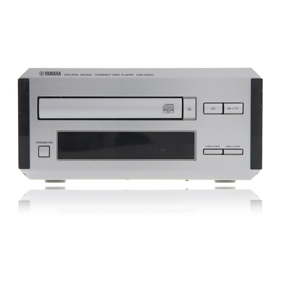
MINI COMPONENT SYSTEM
CDX-E200
CRX-E200 is composed of RX-E200 and
CDX-E200. This is a service manual for
the CDX-E200.
For service manuals of RX-E200, please
refer to the service manuals with the
following publication numbers :
RX-E200
100742
For the system operation, please refer
to Service Manual for the RX-E200.
This manual has been provided for the use of authorized YAMAHA Retailers and their service personnel.
It has been assumed that basic service procedures inherant to the industry, and more specifically YAMAHA Products, are already
known and understood by the users, and have therefore not been restated.
WARNING:
IMPORTANT:
The data provided is believed to be accurate and applicable to the unit(s) indicated on the cover. The research, engineering, and
service departments of YAMAHA are continually striving to improve YAMAHA products. Modifications are, therefore, inevitable
and specifications are subject to change without notice or obligation to retrofit. Should any discrepancy appear to exist, please contact
the distributor's Service Division.
WARNING:
IMPORTANT:
CONTENTS
TO SERVICE PERSONNEL ..................................... 1-2
ELECTROSTATICALLY SENSITIVE DEVICES ......... 2
REAR PANELS ............................................................. 3
SPECIFICATIONS ......................................................... 3
INTERNAL VIEW .......................................................... 4
DISASSEMBLY PROCEDURES .............................. 4-5
STANDARD OPERATION CHART .......................... 6-7
TEST MODE .............................................................. 8-9
1 0 0 7 4 5
SERVICE MANUAL
IMPORTANT NOTICE
Failure to follow appropriate service and safety procedures when servicing this product may result in personal
injury, destruction of expensive components and failure of the product to perform as specified. For these reasons,
we advise all YAMAHA product owners that all service required should be performed by an authorized
YAMAHA Retailer or the appointed service representative.
The presentation or sale of this manual to any individual or firm does not constitute authorization, certification or
recognition of any applicable technical capabilities, or establish a principle-agent relationship of any form.
Static discharges can destroy expensive components. Discharge any static electricity your body may have accumu-
lated by grounding yourself to the ground buss in the unit (heavy gauge black wires connect to this buss).
Turn the unit OFF during disassembly and parts replacement. Recheck all work before you apply power to the unit.
ERROR MESSAGE ............................................... 10-11
IC DATA ................................................................ 12-16
DISPLAY DATA .......................................................... 17
BLOCK DIAGRAM ................................................ 18-19
PRINTED CIRCUIT BOARD ................................ 20-23
IC BLOCK ............................................................. 24-25
PIN CONNECTION DIAGRAM ................................... 25
SCHEMATIC DIAGRAM ............................................. 26
PARTS LIST .......................................................... 27-35
CDX-E200
CRX-E200
Advertisement
Table of Contents

Related Manuals for Yamaha CDX-E200


Summary of Contents for Yamaha CDX-E200
-
Page 1: Table Of Contents
This manual has been provided for the use of authorized YAMAHA Retailers and their service personnel. It has been assumed that basic service procedures inherant to the industry, and more specifically YAMAHA Products, are already known and understood by the users, and have therefore not been restated. -
Page 2: To Service Personnel
CDX-E200 TO SERVICE PERSONNEL AC LEAKAGE Critical Components Information. EQUIPMENT WALL TESTER OR Components having special characteristics are marked Z OUTLET UNDER TEST EQUIVALENT and must be replaced with parts having specifications equal to those originally installed. INSULATING TABLE CAUTION: USE OF CONTROLS OR ADJUSTMENTS OR PERFORMANCE OF PROCEDURES OTHER THAN THOSE SPECIFIED HEREIN MAY RESULT IN HAZARDOUS RADIATION EXPOSURE. -
Page 3: Prevention Of Electrostatic Discharge To Electrostatically Sensitive Devices
CDX-E200 VARO! : AVATTAESSA JA SUOJALUKITUS OHITETTAESSA OLET ALTTIINA NÄKYMÄTTÖMÄLLE LASER-SÄTEILYLLE. ÄLÄ KATSO SÄTEESEEN. VARNING! : OSYNLIG LASERSTRÅLNING NÄR DENNA DEL ÄR ÖPPNAD OCH SPÄRREN ÄR URKOPPLAD. BETRAKTA EJ STRÅLEN. R, B, G models R, B, G models The lavel is under the CD mechanism. -
Page 4: Rear Panels
CDX-E200 REAR PANELS SPECIFICATIONS R model Output Level 2.0 ± 0.5Vrms 1kHz, 0dB Signal to Nosie Ratio (EIAJ) 102dB Dynamic Range 95dB Harmonic Distortion+Noise (1kHz) 0.004% Frequency Response ±0.5dB 2Hz — 20kHz 240V Power Requirements B, G models 230V AC 50Hz... -
Page 5: Internal View
CDX-E200 INTERNAL VIEW MAIN (4) P.C.B. MAIN (5) P.C.B. MAIN (1) P.C.B. CD MECHANISM UNIT MAIN (3) P.C.B. MAIN (2) P.C.B. DISASSEMBLY PROCEDURES (Remove parts in disassembly order as numbered.) 1. Removal of Top Cover a. Remove 4 screws ( q ) and 4 screws ( w ) in Fig. 1. - Page 6 CDX-E200 4. Removal of Tray Unit Stopper Pin Chucking Unit a. Remove 2 screws ( y ) and then remove the Chuck- ing Unit in Fig. 3. b. Remove 1 hook and then remove the Stopper Pin in Stopper Fig. 3.
-
Page 7: Standard Operation Chart
CDX-E200 STANDARD OPERATION CHART POWER ON If a disc is not loaded, “– –:– –” appears in the time indicator. Press OPEN/CLOSE key. “ OPEN ” appears in the indicator. “TRV” signal is output until detection of LIMIT switch. Forced feed return operation... - Page 8 CDX-E200 Tracking gain rough ADJ Tracking balance ADJ (only tray OPEN/CLOSE) Focus balance ADJ Focus gain ADJ Tracking gain ADJ * TOC READ ~ * Data fetch cycle ~ TRACK NO. “1” is searched. : MUTE OFF = “H” → “L” (Q7 Collector) After searching the beginning, MUTE is cancelled.
-
Page 9: Test Mode
CDX-E200 TEST MODE Turning ON the POWER while pressing the keys “STOP” and “PLAY/PAUSE” will set to the TEST mode. (When the TEST mode is set, all indicators light for 1 second.) Note: When the power off, “STOP” key must be pressed before “PLAY/PAUSE” key pressd. Otherwise “PLAY/ PAUSE”... -
Page 10: Test Mode
CDX-E200 Test mode function List of Remote Controller keys System Control FUNCTION Code All stop. (Focus, spindle, traverse, laser, tray, etc.) PLAY (FOON, TRON, TVON(FEON), SPON) Move traverse forward. Move traverse reverse till the inner SW turn on. RANDOM SPON (Spindle servo on.) TEXT/TIME Check FL display. -
Page 11: Error Message
CDX-E200 ERROR MESSAGE (1) If stopped by any cause, error message can be displayed by pressing the remote STOP key while pressing and holding the panel STOP key, or by test mode command number 23. The player holds the latest error message in EEPROM. So even if stopped with no error, the latest error message can be displayed with same operation. - Page 12 CDX-E200 c) Operates as if no disc loaded. (although loaded) 2) Troubleshooting from System Malfunctions a) Tray fails to come out/go in. Does tray Poor tray loading load properly? Poor mechanism Tray starts to operation move but stops. Wire caught.
-
Page 13: Ic Data
CDX-E200 IC DATA IC103 : µPD78076GF-103-3BA 8bit µ-COM Name Function Port OPSW Opened state of tray sensing switch input. Opened state at “L”. P120/RTP0 CLSW Closed state of tray sensing switch input. Closed state at “L”. P121/RTP1 N.C. P122/RTP2 MUTE Sound output at “H”... - Page 14 CDX-E200 IC103 : µPD78076GF-103-3BA 8bit µ-COM Port Name Function P13/ANI3 N.C. P14/ANI4 DATA port for EEPROM. P15/ANI5 DATA CLOCK for EEPROM. P16/ANI6 N.C. P17/ANI7 LDRCTL Laser ON control AVSS AVSS P130/ANO0 OP/CL Tray open/close signal output P131/ANO1 GCTRL Gain and APC control AVREF1 N.C.
- Page 15 CDX-E200 IC103 : µPD78076GF-103-3BA 8bit µ-COM Port Name Function P67/ASTB P100/TI5/TO5 P101/TI6/TO6 P102 P103 P30/TO0 N.C. P31/TO1 P32/TO2 P33/TI1 P34/TI2 P35/PCL P36/BUZ STAN M56748 standby control Pull down Pull down Monitor 1 Monitor 2 Monitor 3 Monitor 4 Monitor (error) IC102 : MN35511AL Signal Processor &...
- Page 16 CDX-E200 IC102 : MN35511AL Signal Processor & Controller Pin No. Name Function BCLK Bit clock output for SR DATA (NC) LRCK L/R identification signal output (NC) SRDATA Serial data output (NC) DVDD1 Power supply for digital circuit (+5) DVSS1 GND for digital circuit...
- Page 17 CDX-E200 IC102 : MN35511AL Signal Processor & Controller Pin No. Name Function DSLF Loop filter terminal for DSL PLLF Loop filter terminal for PLL VCOF Loop filter terminal for VCO (+5) AVDD2 Power supply for analog circuit (for AD of DSL, PLL, DA output blocks)
-
Page 18: Display Data
CDX-E200 DISPLAY DATA (V3618100) V301 : 14-BT-56GN &0 PATTERN AREA PIN CONNECTION Pin No. Connection F1 NP 14G 13G 12G 11G 10G 9G 8G 7G 6G 5G 4G 3G 2G NX NX NX NX 1G IC P35 P34 P33 P32 P31 P30 P29 P28 Pin No. -
Page 19: Block Diagram
CDX-E200 BLOCK DIAGRAM CD MECHA. UNIT XL101 PICK UP OUT L HEAD IC101 CONTROL LINE OUT AN8399SA LD DRIVE IC102 MN35511AL VREF OUT R SPC+DAC MUTE KICK CONTROL AN8785SB D1–5 FCS+ TRK+ DIGITAL OUT 6 TX TRK– OPTICAL MDATA FCS–... -
Page 20: Printed Circuit Board
CDX-E200 PRINTED CIRCUIT BOARD (Foil side) Point q (Pin 59 of IC102) MAIN ( 1 ) P. C. B. MAIN ( 2 ) P. C. B. Semiconductor Location V : 2V/div, H : 50nsec/div Ref. No. Location DC, 1 : 1 probe... -
Page 21: Printed Circuit Board
CDX-E200 PRINTED CIRCUIT BOARD (Foil side) Point e (Pin 58 of IC301) MAIN ( 3 ) P. C. B. V : 2V/div, H : 0.2µsec/div DC, 1 : 1 probe OPEN/ STOP CLOSE PLAY PAUSE /BLK STANDBY/ FROM : MAIN (2) MAIN ( 4 ) P. -
Page 22: Ic Block
CDX-E200 IC BLOCK IC101 : AN8399SA IC301 : LC75710NE IC1 : AN87855SB CD Head Amp FL Driver 5-Channel Power OP-Amp System Driver SHIFT DC RAM REGISTER AM32 AM31 Thermal AM30 Protection AM29 ADDRESS ADDRESS RF EQ OFTR Circuit AM35 REGISTER... -
Page 23: Schematic Diagram
CDX-E200 SCHEMATIC DIAGRAM Point q (Pin 59 of IC102) V : 2V/div, H : 50nsec/div DC, 1 : 1 probe MUTING –5.0 –5.0 Point w (Pin 10 of IC103) V : 2V/div, H : 0.2µsec/div DC, 1 : 1 probe SPC &... -
Page 24: Parts List
CDX-E200 P ARTS LIST WARNING Components having special characteristics are marked and must be replaced with parts having specifications equal to those originally installed. ELECTRICAL PARTS Carbon resistors (1/6W or 1/4W) are not included in the ELECTRICAL PARTS List. For the part Nos. of the carbon resistors, refer to the last page. - Page 25 CDX-E200 ! : Note on the Main PCB Of the main PCB part Nos., only the gold (GD) type part Nos. are included in the table. The only different part between the silver (SI) and gold (GD) type parts is the sheet/FL that is attached to the fluorescent character display tube.
- Page 26 CDX-E200 Schm Schm Ref. PART NO. Description Market Ref. PART NO. Description Market C146 UA652560 C.MYLAR 560pF VK432900 TR 2SD1915F S,T C147 UA652560 C.MYLAR 560pF VK432900 TR 2SD1915F S,T C148 UA652120 C.MYLAR 120pF V6706700 TR 2SA1267 GR,Y C149 VG286200 C.EL...
-
Page 27: Exploded View
CDX-E200 EXPLODED VIEW 1-21 1-21 1-13 1-20 1-12 1-11 1-20 1-14 1-13... - Page 28 CDX-E200 MECHANICAL PARTS Ref. PART NO. Description Remarks Markets MF114100 FLEXIBLE FLAT CABLE 14P 100mm * 1-11 V6777900 FRONT PANEL * 1-11 V6774000 FRONT PANEL 1-12 V3686900 SUB PANEL-CDX 1-12 V3810500 SUB PANEL-CDX 1-13 V3687400 PANEL, SIDE-H81 1-14 V3688000 SHEET, WINDOW-CDX...
- Page 29 CDX-E200 EXPLODED VIEW (CD Mechanism Unit) Stopper * The stopper is not supplied with the tray as a spare part. When replacing the tray, keep the removed stopper and reuse it. Should it be lost and a new one be necessary, order service part Main Chassis (S) and remove the stopper only from it and use it as a spare part.
- Page 30 CDX-E200 MECHANICAL PARTS (CD Mechanism Unit) Ref. PART NO. Description Remarks Markets VZ573200 CD MECHANISM UNIT KSL-2130CCM CX680620 TRAY (C) 2130 264629001 CX675250 GEAR COVER (S) 262554401 CX675210 TRAY GEAR (S) 262553501 AX619150 CHUCKING PLATE (S) 262554601 EX602890 BW HEAD P-TITE SCREW 2.6x7...
- Page 31 CDX-E200 EXPLODED VIEW (Drive Unit) Note : The parts marked with an asterisk ( ) are not available separately. Cover Ref. PART NO. Description Remarks Markets NX635420 MOTOR CHASSIS ASS'Y (MB) X26258771 CX679710 MOTOR GEAR ASS'Y X26257691 AX623980 SLED SHAFT...
-
Page 32: Parts List For Carbon Resistors
CDX-E200 Parts List for Carbon Resistors Value 1/4W Type Part No. 1/6W Type Part No. Value 1/4W Type Part No. 1/6W Type Part No. 1.0 Ω 3100 3100 7100 10 kΩ 7100 HJ35 HF85 HF45 HF45 1.8 Ω 3180 7110 11 kΩ... - Page 33 CDX-E200...
Need help?
Do you have a question about the CDX-E200 and is the answer not in the manual?
Questions and answers