Table of Contents
Advertisement
Available languages
Available languages
Quick Links
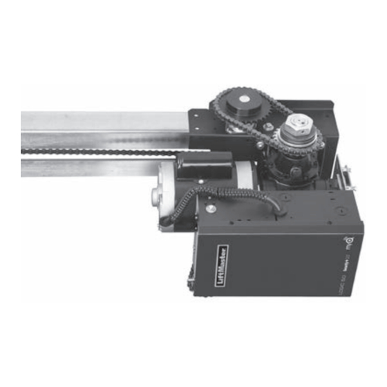
Logic 5.0 Commercial Door Operator
NOT FOR RESIDENTIAL USE
• Please read this manual and the enclosed safety materials completely, prior to installation
and use
• This Product Is To Be Installed And Serviced By A Trained Door Systems Technician nly.
• A LiftMaster Monitored Entrapment Protection (LMEP) Device is EQUI ED for B2, T, TS,
and FSTS
• Upon completion of installation, test entrapment protection device(s) prior to placing the
operator into active use.
• These operators are compatible
LiftMaster
300 Windsor Drive
Oak Brook, IL 60523
INSTALLATION MANUAL
®
Models GSD and SD
iring types.
ith MyQ
and Security+ 2.0
accessories.
®
®
Advertisement
Chapters
Table of Contents
Troubleshooting

Related Manuals for Chamberlain GSD series


Summary of Contents for Chamberlain GSD series
- Page 1 Logic 5.0 Commercial Door Operator INSTALLATION MANUAL ® Models GSD and SD NOT FOR RESIDENTIAL USE • Please read this manual and the enclosed safety materials completely, prior to installation and use • This Product Is To Be Installed And Serviced By A Trained Door Systems Technician nly. •...
-
Page 2: Table Of Contents
TABLE OF CONTENTS SAFETY INFORMATION TROUBLESHOOTING 27-30 INTRODUCTION Diagnostic Chart Carton Inventory Troubleshooting Guide Hardware Kits Troubleshooting Error Codes Operator Specifications Troubleshooting Radio Functionality Maximum Door Area Operator Dimensions WIRING DIAGRAMS 31-32 Logic 5.0 Single Phase Wiring Diagram Logic 5.0 Three Phase Wiring Diagram ASSEMBLY ACCESSORIES 33-35... -
Page 3: Safety Information
SAFETY INFORMATION IMPORTANT NOTES: • BEFORE attempting to install, operate or maintain the operator, Mechanical you must read and fully understand this manual and follow all safety instructions. • DO NOT attempt repair or service of your commercial door and gate operator unless you are an Authorized Service Technician. -
Page 4: Introduction
INTRODUCTION CARTON INVENTORY Before beginning your installation check that all components were provided. DESCRIPTION Powerhead assembly Owner’s manual and caution labels Hardware box (includes fasteners, track spacers, trolley, door arm assembly, front idler and header mounting bracket) 3-Button control station with MAS LED Trolley drive chain NOTE: The tracks are shipped separately. -
Page 5: Operator Specifications
OPERATOR SPECIFICATIONS MOTOR SAFETY DISCONNECT: ... . . Quick disconnect door arm TYPE: ..... . . Continuous duty for emergency manual door operation. -
Page 6: Operator Dimensions
OPERATOR DIMENSIONS MODEL GSD Single Slide Door Layout 4" (10.16 cm) Adjustable clearance for door movement between wall and operator. 7.5" (19.05 cm) Max. 6" (15.24 cm) Min. 13" 12.02" (33.02 cm) (30.5 cm) Door Travel Plus 4' (1.2 m) - 3" (7.62 cm) 18"... -
Page 7: Assembly
ASSEMBLY Refer to page 7 for illustrations. Lay out the two pieces of track on the floor, parallel to each To prevent possible SERIOUS INJURY or DEATH: other and install the end idler shaft assembly. • DO NOT connect electric power until instructed to do so. NGLISH WARNINGS AT 50% •... -
Page 8: Assembly
Idler Shaft Assembly Angle Mounting Bracket Hex Head Bolt, 3/8-16 x 1" long (2 per bracket) Track Hanger Flat Washer, 1/8" (2 per bracket) Bi-part Trolley Single Door Trolley Operator Hex Nut, 3/8" (4 per bracket) BI-PART TROLLEY ASSEMBLY SINGLE DOOR TROLLEY ASSEMBLY Serrated Flange Hex Nut, #10 Screw, #10-32 x 1-1/4"... -
Page 9: Installation
INSTALLATION TYPICAL INSTALLATION To avoid possible SERIOUS INJURY from a falling operator: NOTE: Refer to Operator Dimensions in the introduction for general information. • Fasten the operator SECURELY to structural supports of the ENGLISH WAR building. Determine the clearance necessary for the door to pass •... -
Page 10: Fusible Link (Optional)
Door Travel Plus 4' (1.2 m) - 3" (7.62 cm) 18" (45.72 cm) Min. FUSIBLE LINK (OPTIONAL) NOTE: Refer to Operator Dimensions in the introduction for general information. Mount chain retaining bracket to door, approximately 17.13" 4 feet (1.2 m) above the floor and 2" (5.1 cm) off center-line (43.51 cm) of door. -
Page 11: Wiring
WIRING WARNING To reduce the risk of SEVERE INJURY or DEATH: • ALL electrical connections MUST be made by a qualified individual. • ANY maintenance to the operator or in the area near the operator MUST NOT be performed until disconnecting the •... -
Page 12: Control Station
CONTROL STATION To prevent possible SERIOUS INJURY or DEATH from • Install the entrapment warning placard on wall next to the electrocution: control station in a prominent location that is visible from the WARNINGS AT 50% door. • Be sure power is NOT connected BEFORE installing door control. -
Page 13: Entrapment Protection
ENTRAPMENT PROTECTION LIFTMASTER MONITORED ENTRAPMENT PROTECTION (LMEP) To prevent possible SERIOUS INJURY or DEATH from a closing IMPORTANT INFORMATION ABOUT THE LIFTMASTER door: MONITORED ENTRAPMENT PROTECTION DEVICES NGLISH WARNINGS AT 50% • Be sure power is NOT connected to the door operator BEFORE A LiftMaster Monitored Entrapment Protection (LMEP) Device is installing the photoelectric sensor. -
Page 14: Entrapment Protection
INSTALL THE LIFTMASTER MONITORED ENTRAPMENT PROTECTION (LMEP) DEVICES (OPTIONAL) Always refer to the installation instructions that are included with your LiftMaster Entrapment Protection (LMEP) Devices. Without an LMEP properly installed, the operator will only work with constant pressure to close mode of operation. WIRE THE LIFTMASTER MONITORED ENTRAPMENT PROTECTION (LMEP) DEVICES Connect the LiftMaster Monitored Entrapment Protection... -
Page 15: Adjustment
WARNING ADJUSTMENT IMPORTANT SAFETY INSTRUCTIONS WARNING TO REDUCE THE RISK OF SEVERE INJURY OR DEATH: 1. READ AND FOLLOW ALL WARNINGS AND INSTRUCTIONS. 8. After ANY adjustments are made, the entrapment protection device MUST be tested. Failure to adjust the operator 2. -
Page 16: Clutch Adjustment (Model Sd)
CLUTCH ADJUSTMENT (MODEL SD) Remove the cotter pin from the clutch nut on the clutch shaft. To avoid SERIOUS personal INJURY or DEATH from electrocution: NGLISH WARNINGS AT 50% Turn the clutch nut to release tension. • Disconnect electric power BEFORE performing ANY adjustments or maintenance. -
Page 17: Testing
TESTING Apply power to the operator. When power is applied to the operator, the following LED’s will illuminate: STOP, CLOSE, OPEN, LMEP, 24Vac, RADIO, DATA, To avoid SERIOUS personal INJURY or DEATH: TIMER ENABLE, OLS MID, SLS, CLS, and MAS. Once the power •... -
Page 18: Manual Release
MANUAL RELEASE The door cannot be moved manually with the trolley connected. However, a quick disconnect pin and chain mechanism is provided to uncouple the door from the trolley. To disengage the To prevent possible SERIOUS INJURY or DEATH from a falling door, simply pull the chain down and engage it in the keyhole slot door or arm: an the bracket provided for this purpose. -
Page 19: Programming
PROGRAMMING INTRODUCTION TO PROGRAMMING Many programmable functions require that a LiftMaster LOGIC BOARD PUSH BUTTONS (OPEN, CLOSE, STOP) Entrapment Protection (LMEP) Device be installed in order to Open, Close and Stop buttons are mounted directly on the logic function. Refer to the Entrapment Protection section. board. -
Page 20: Determine And Set Wiring Type
DETERMINE AND SET WIRING TYPE Read the descriptions of the different wiring types to determine which setting will be correct for each application. Once the wiring type is determined, set the selector dial accordingly. LIFTMASTER MONITORED ENTRAPMENT PROTECTION (LMEP) LIFTMASTER MONITORED ENTRAPMENT PROTECTION (LMEP) DEVICE IS REQUIRED DEVICE IS RECOMMENDED A LiftMaster Entrapment Protection (LMEP) Device is required for... -
Page 21: Programming Remote Controls
PROGRAMMING REMOTE CONTROLS To prevent possible SEVERE INJURY or DEATH: • Activate door ONLY when it can be seen clearly, is properly • Install a LiftMaster Monitored Entrapment Protection (LMEP) adjusted and there are no obstructions to door travel. Device. •... - Page 22 PROGRAMMING REMOTE CONTROLS REMOTE CONTROL PROGRAMMING FEATURE NOTE: The following programming requires a LiftMaster Monitored Entrapment Protection (LMEP) Device. Program Remote Controls from the 3-button control station Your Security+ 2.0 or dip switch remote control can be (3BCS). ® programmed to operate as a 3-button wireless control station: This feature allows the user to add additional remote controls the large button will open the door, the middle button will close from the 3BCS.
-
Page 23: Programming Myq Devices (Optional)
PROGRAMMING MyQ DEVICES (OPTIONAL) ® To Program MyQ Devices: 2. Press and hold the MAS button for 5 seconds. The RADIO LED 1. To enter programming mode, press and release the RADIO button will flash for approximately 5 seconds and the RADIO LED will on the logic board (the RADIO LED will light). -
Page 24: Open Mid Stop
OPEN MID STOP Feature: The Mid Stop feature is to open the door to a preset point prior to the fully open position. SELECTOR DIAL Benefit: The door opens to a midpoint between open and close reducing heating and cooling costs. The door will not cycle fully, providing longer door and operator life. -
Page 25: Car Dealer Mode
TIMER-TO-CLOSE PROGRAM TIMER-TO-CLOSE BY EXAMPLE (Method 2): TO PROGRAM: 1. Close the door. SELECTOR DIAL 2. Turn the selector dial to PROG. 3. Press and hold TIMER button for 5 seconds until OPEN and OLS flashes then release. 4. Press and release the OPEN button and wait for the door to reach full open or mid stop position. -
Page 26: Maximum Run Timer (Mrt)
MAXIMUM RUN TIMER (MRT) Feature: The operator can learn the time it takes to open or close SELECTOR DIAL the door plus and an additional 10 seconds. Benefit: If the operator does not meet its open or close limit within the set time it will stop, limiting damage to the door and operator. -
Page 27: Maintenance
MAINTENANCE MAINTENANCE SCHEDULE For use with Maintenance Alert System. Check at the intervals listed in the following chart: To avoid SERIOUS personal INJURY or DEATH: • Disconnect electric power BEFORE performing ANY NGLISH WARNINGS AT 50% adjustments or maintenance. • ALL maintenance MUST be performed by a trained door systems technician. -
Page 28: Troubleshooting
TROUBLESHOOTING DIAGNOSTIC CHART The logic board has several LEDs to assist in the installation and troubleshooting of the operator. The following chart should assist in verifying the operator is functioning properly. Turn the selector dial to DIAG to keep the door from moving while troubleshooting. COLOR DEFINITION Power... -
Page 29: Troubleshooting Guide
TROUBLESHOOTING GUIDE FAULT POSSIBLE CAUSE A RELAY CLICK IS HEARD This is normal operation. No action necessary. See Logic Board Overview (page 18) for more information regarding current sense. WHEN GIVEN A COMMAND SLIGHTLY BEFORE MOTOR MOVEMENT. RELAY LED'S ON BOARD FLASH IN UNISON WITH THE CLICK. -
Page 30: Troubleshooting Error Codes
TROUBLESHOOTING ERROR CODES Logic 5.0 operators incorporate a self diagnostic feature built into the MAS LED. In addition to indicating when routine maintenance is due, the MAS LED can be used to troubleshoot problems with the operator. If the MAS LED on the logic board or 3-button control station is flashing on and off rapidly, the Maintenance Alert System has been triggered and service is due on the operator. -
Page 31: Troubleshooting Radio Functionality
TROUBLESHOOTING RADIO FUNCTIONALITY The error codes will display at the radio LED. NOTE: Radio receiver is compatible with SECURITY+ 2.0 remote controls ® and keyless entry devices. ERROR CODE DISPLAY SYMPTOM POSSIBLE PROBLEM CORRECTION Quick Flash No response from the remote Unlearned remote control- Try re-learning the remote control control. -
Page 32: Wiring Diagrams
WIRING DIAGRAMS LOGIC (VER. 5.0) 1 PHASE WIRING DIAGRAM Refer to page 13 for Refer to page 21 for LiftMaster Monitored LiftMaster Monitored Entrapment Protection Entrapment Protection (LMEP) Device (LMEP) device connections. connections Wiring Diagrams... - Page 33 LOGIC (VER. 5.0) 3 PHASE WIRING DIAGRAM Refer to page 21 for LiftMaster Monitored Entrapment Protection (LMEP) device connections. Wiring Diagrams...
-
Page 34: Accessories
ACCESSORIES ENTRAPMENT PROTECTION DEVICES MONITORED MONITORED CPS-U Dual-Sided Infrared Photo Eyes CPS3CARD Safety Interface Card • NEMA 1 general purpose enclosure. Plug-in Interface card enables use of a second set of • Dual-sided infrared sensors. monitored photo eyes or edge with a commercial Optical Edge System (OES) door operator. - Page 35 ACCESSORIES ACCESSORIES ® CONTROL STATIONS 02-101 1-Button Control Station: 828LM LiftMaster Internet Gateway ® Steel enclosure. Enables owners of Commercial Door Operators to open and close their doors and turn on/off lights in or around their facility using a smart phone or tablet computer from anywhere in the world.
- Page 36 02-401M ACCESSORIES MOUNTING BRACKETS ADDITIONAL CONTROL ACCESSORIES Heavy gauge steel bracket for vertical or horizontal 10-12360 TLS1CARD 86LM (15' [4.6 m]) Antenna Extension Kit: mount on either front or top of coil on a rolling door. 86LMT (25' [7.6 m]) The antenna extension kit can be used with EXT-ANT Has a variety of mounting hole patterns compatible for maximum radio receiver range.
- Page 37 NOTES...
-
Page 38: Control Connections Diagram
CONTROL CONNECTION DIAGRAM IMPORTANT NOTES: 1. The 3-Button Control Station provided must be connected for operation. 2. If a STOP button is not used, a jumper must be placed between terminals 4 and 5. 3. When adding accessories, install them one at a time and test each one after it is added to ensure proper installation and operation with the Commercial Door Operator. - Page 39 Actionneur de porte commerciale Logic 5.0 MANUEL D’INSTALLATION ® Modèles GSD et SD N’EST PAS DESTINÉ À UNE UTILISATION RÉSIDENTIELLE • Lire au complet ce manuel et la documentation de sécurité qui l’accompagne avant d’installer ou d’utiliser l’actionneur. • Ce produit doit être exclusivement installé et entretenu par un technicien dûment formé sur les systèmes de porte.
- Page 40 TABLE DES MATIÈRES INFORMATIONS DE SÉCURITÉ DÉPANNAGE 27-30 INTRODUCTION Fiche diagnostique Contenu de l’emballage Guide de dépannage Nécessaires de quincaillerie Codes d’erreur de dépannage Spécifications de l’ouvre-porte Fonctionnalité de dépannage par radio Zone de porte maximale Dimensions de l’actionneur SCHÉMAS DE CÂBLAGE 31-32 Logic 5.0 Schéma de câblage 1 phase ASSEMBLAGE...
-
Page 41: Informations De Sécurité
NINGS AT 50% ENGLISH WARNINGS AT 50% INFORMATIONS DE SÉCURITÉ REMARQUES IMPORTANTES : • AVANT d'essayer d'installer, de faire fonctionner ou d'assurer Mécanique l'entretien de l'ouvre-porte, vous devez lire et comprendre intégralement ce manuel et appliquer toutes les instructions de sécurité. -
Page 42: Introduction Contenu De L'emballage
INTRODUCTION CONTENU DE L’EMBALLAGE Avant de commencer votre installation, vérifier que tous les composants ont été fournis. DESCRIPTION Assemblage de la tête motorisée Manuel d’instructions et étiquettes de précaution Boîte de quincaillerie (comprend les fixations, les entretoises de rail, le chariot, l’assemblage de bras de porte, la poulie libre avant et le support de montage de linteau) Station de commande à... -
Page 43: Spécifications De L'ouvre-Porte
SPÉCIFICATIONS DE L'OUVRE-PORTE MOTEUR SÉCURITÉ TYPE : ....... . Service continu DÉCONNEXION : . - Page 44 DIMENSIONS DE L’OUVRE-PORTE MODÈLE GSD Arrangement pour une porte 10,16 cm (4 po) Dégagement réglable pour le mouvement de la porte entre le mur et l’actionneur. coulissante à simple battant 19,05 cm po (7,5) Max. 15,24 cm (6 po) Min. 33,02 cm (30,5 cm) (13 po)
-
Page 45: Assemblage
ASSEMBLAGE Reporter à la page 7 pour illustrations. Étendre les deux pièces du rail sur le sol, parallèlement l’une à Pour empêcher une BLESSURE GRAVE ou une MORT possible : l’autre et installer l’arbre de poulie d’extrémité. • NE PAS connecter l'alimentation électrique avant d'avoir reçu FRENCH WARNINGS AT 50% l'instruction de le faire. - Page 46 Ensemble d’arbre de poulie Support de montage à angle Boulon à tête hexagonale de 3/8 de po-16 x 1 po de long (2 par support) Cintre de rail Rondelle plate , 1/8 de po (2 par support) Chariot de porte à deux vantaux Chariot de porte simple Actionneur Écrou hexagonal.
-
Page 47: Installation
INSTALLATION INSTALLATION TYPIQUE REMARQUE : Se reporter aux dimensions de l’actionneur dans Pour éviter une BLESSURE GRAVE possible causée par un ouvre-porte qui tombe : l’introduction pour de l’information générale. FRENCH WARN • Fixer SOLIDEMENT l'ouvre-porte aux supports de structure du bâtiment. -
Page 48: Maillon Fusible (En Option)
Door Travel Plus 4' (1.2 m) - 3" (7.62 cm) 18" (45.72 cm) Min. MAILLON FUSIBLE (EN OPTION) REMARQUE : Se reporter aux dimensions de l’actionneur dans l’introduction pour de l’information générale. Monter le support de retenue de la chaîne sur la porte, à 17.13"... -
Page 49: Câblage
CÂBLAGE Pour réduire le risque de BLESSURES GRAVES ou de MORT: • TOUTES les connexions électriques DOIVENT être faites par un individu qualifié. • AUCUN entretien de l'ouvre-porte ou dans la zone près de CH WARNINGS AT 50% l'ouvre-porte NE DOIT être effectué tant que l'alimentation •... -
Page 50: Station De Commande
STATION DE COMMANDE Pour empêcher une BLESSURE GRAVE ou une MORT possible • Installer le placard d'avertissement contre le piégeage sur le par électrocution : mur adjacent à la station de commande sur un emplacement CH WARNINGS AT 50% parfaitement visible depuis la porte. •... -
Page 51: Protection Contre Le Piégeage
PROTECTION CONTRE LE PIÉGEAGE PROTECTION CONTRE LE PIÉGEAGE AVEC SURVEILLANCE LIFTMASTER (LMEP) Pour empêcher une BLESSURE GRAVE ou une MORT possible à cause d'une porte qui se ferme : FRENCH WARNINGS AT 50% RENSEIGNEMENTS IMPORTANTS AU SUJET DES DISPOSITIFS • S'assurer que l'alimentation N'EST PAS connectée à l'ouvre- DE PROTECTION CONTRE LE PIÉGEAGE AVEC SURVEILLANCE porte AVANT d'installer le capteur photoélectrique. - Page 52 INSTALLATION DES DISPOSITIFS DE PROTECTION CONTRE LE PIÉGEAGE AVEC SURVEILLANCE LIFTMASTER (LMEP) (FACULTATIVE) Référez-vous toujours aux directives d’installation incluses avec votre dispositif de protection contre le piégeage LiftMaster (LMEP). Sans un dispositif de protection contre le piégeage correctement installé, l’actionneur ne fonctionnera qu’avec une pression constante pour désactiver le mode de fonctionnement.
-
Page 53: Réglages
RÉGLAGES INSTRUCTIONS DE SÉCURITÉ IMPORTANTES POUR RÉDUIRE LE RISQUE DE BLESSURES GRAVES, VOIRE MORTELLES : CH WARNINGS AT 50% 1. LIRE ET SUIVRE TOUS LES AVERTISSEMENTS ET TOUTES 8. Après avoir effectué TOUT ajustement, le dispositif de LES INSTRUCITONS protection contre le piégeage DOIT être testé. Le défaut d'ajuster l'ouvre-porte correctement peut causer une 2. -
Page 54: Réglage De L'embrayage (Modèle Sd)
RÉGLAGE DE L'EMBRAYAGE (MODÈLE SD) Pour éviter des BLESSURES personnelles SÉRIEUSES ou la Retirer la goupille fendue de l'écrou d'embrayage sur l'arbre MORT par électrocution : FRENCH WARNINGS AT 50% d'embrayage. • Déconnecter l'alimentation électrique AVANT d'effectuer Tourner l'écrou d'embrayage pour relâcher la tension. TOUT ajustement ou entretien. -
Page 55: Test
TEST Appliquer l'alimentation à l'ouvre-porte. Lorsque l'alimentation est appliquée à l'ouvre-porte, les DEL suivantes s'allument : STOP (arrêt), CLOSE (fermer), OPEN Pour éviter des BLESSURES personnelles SÉRIEUSES ou la (ouvrir), LMEP, 24 Vca, RADIO, DATA (données), TIMER ENABLE MORT : (permettre minuterie), OLS (inter. -
Page 56: Dégagement Manuel
DÉGAGEMENT MANUEL La porte ne peut pas être déplacée manuellement lorsque le chariot est connecté. Toutefois, une tige de désaccouplement Pour empêcher une BLESSURE GRAVE ou une MORT possible rapide et un mécanisme à chaîne sont fournis afin de à cause d'une porte ou d'un bras qui tombe : désaccoupler la porte du chariot. -
Page 57: Programmation
PROGRAMMATION INTRODUCTION À LA PROGRAMMATION Plusieurs fonctions programmables exigent qu'un dispositif de REMARQUE : Lorsque de processus de mise sous tension est Protection contre le piégeage LiftMaster (LMEP) soit installé complété, la DEL MAS clignotera un code indiquant la version du pour fonctionner. -
Page 58: Détermination Et Configuration Du Type De Câblage
DÉTERMINATION ET CONFIGURATION DU TYPE DE CÂBLAGE Lire les descriptions des différents types de câblage pour déterminer quelle configuration sera correcte pour chaque application. Lorsque le type de câblage est déterminé, configurer le cadran de réglage en conséquence. UN DISPOSITIF DE PROTECTION CONTRE LE PIÉGEAGE AVEC UN DISPOSITIF DE PROTECTION CONTRE LE PIÉGEAGE AVEC SURVEILLANCE LIFTMASTER (LMEP) EST NÉCESSAIRE SURVEILLANCE LIFTMASTER (LMEP) EST RECOMMANDÉ... -
Page 59: Programmation Des Télécommandes
PROGRAMMATION DES TÉLÉCOMMANDES Pour empêcher une BLESSURE GRAVE ou une MORT possible : • Activer la porte SEULEMENT lorsqu'elle peut être vue clairement, qu'elle est correctement ajustée et qu'il n'y a • Installer un dispositif de Protection contre le piégeage avec aucune obstruction au déplacement de la porte. - Page 60 PROGRAMMATION DES TÉLÉCOMMANDES FONCTION DE PROGRAMMATION DE LA TÉLÉCOMMANDE REMARQUE : La programmation suivante nécessite un dispositif de Protection contre le piégeage avec surveillance LiftMaster (LMEP). Programmation de télécommandes à partir de la station de Votre télécommande Security+ 2.0 ou DIP programmable peut commande à...
-
Page 61: Programmation Des Dispositifs Myq (Facultative)
PROGRAMMATION DES DISPOSITIFS MyQ (FACULTATIVE) ® Pour programmer les dispositifs MyQ : 2. Pressez et maintenezenfoncé le bouton MAS pendant 5 secondes. Le bouton DEL RADIO clignotera pendant approximativement 1. Pour accéder au mode de programmation, appuyez sur le bouton 5 secondes, puis s’éteindra. -
Page 62: Ouverture À Mi-Course
OUVERTURE À MI-COURSE Pour annuler le réglage de mi-course, placer le cadran de réglage à Caractéristique : La fonction mi-course est pour ouvrir la porte à PROG puis appuyer et tenir le bouton MID durant 5 secondes. La un point prédéterminé avant la position entièrement ouverte. DEL MID clignotera rapidement et s'éteindra lorsque la mi-course Avantage : La porte s'ouvre à... -
Page 63: Mode Concessionnaire Automobile
MINUTERIE DE FERMETURE PROGRAMMATION DE LA MINUTERIE DE FERMETURE PAR EXEMPLE (MÉTHODE 2) : POUR PROGRAMMER : 1. Fermer la porte. CADRAN DE RÉGLAGE 2. Tourner le cadran de réglage à PROG. 3. Appuyer et tenir le bouton TIMER (minuterie) durant 5 secondes jusqu'à... -
Page 64: Minuterie De Fonctionnement Maximal (Mrt)
MINUTERIE DE FONCTIONNEMENT MAXIMAL (MRT) Caractéristique : L'ouvre-porte peut apprendre le temps CADRAN DE RÉGLAGE nécessaire pour ouvrir ou fermer la porte plus ajouter un 10 secondes supplémentaires. Avantage : Si l'ouvre-porte n'atteint pas la fin de course ouvert ou fermée dans le temps configuré, il s'arrêtera, limitant le dommage à... -
Page 65: Entretien
ENTRETIEN PÉRIODICITÉS D'ENTRETIEN Pour utilisation avec le Système d'alerte d'entretien. Vérifier aux intervalles énumérés dans le tableau suivant : Pour éviter des BLESSURES personnelles SÉRIEUSES ou la MORT : • Déconnecter l'alimentation électrique AVANT d'effectuer TOUT FRENCH WARNINGS AT 50% ajustement ou entretien. -
Page 66: Dépannage
DÉPANNAGE FICHE DIAGNOSTIQUE La carte logique a plusieurs DEL pour aider à l'installation et au dépannage de l'ouvre-porte. Le tableau suivant devrait aider à vérifier si l'ouvre-porte fonctionne correctement. Tourner le cadran de réglage à DIAG pour empêcher la porte de bouger durant le dépannage. COULEUR DÉFINITION Power (alim.) -
Page 67: Guide De Dépannage
GUIDE DE DÉPANNAGE DÉFAUT CAUSE POSSIBLE CORRECTION UN DÉCLIC DU RELAIS SE FAIT Ceci est tout à fait normal. Aucune mesure n’est nécessaire. Voir Présentation de la carte logique (page 18) pour ENTENDRE LORSQU’UNE plus d’information sur la détection de courant. COMMANDE A ÉTÉ... -
Page 68: Codes D'erreur De Dépannage
CODES D'ERREUR DE DÉPANNAGE Les ouvre-portes Logic 5.0 comprennent une fonction d'auto-diagnostic intégrée dans la DEL MAS. En plus d'indiquer quand l'entretien de routine est dû, la DEL MAS peut être utilisée pour dépanner certaines problèmes de l'ouvre-porte. Si la DEL MAS sur la carte logique ou sur le poste de commande à trois boutons clignote rapidement, c’est que le système d’alerte d’entretien s’est déclenché... -
Page 69: Fonctionnalité De Dépannage Par Radio
FONCTIONNALITÉ DE DÉPANNAGE PAR RADIO Les codes d'erreur s'affichent dur la DEL radio. REMARQUE : Le récepteur radio est compatible avec les télécommandes et les dispositifs sans clés du SECURITY+ 2.0 ® CODE AFFICHAGE SYMPTÔME PROBLÈME POSSIBLE CORRECTION D’ERREUR Clignotement rapide Aucune réponse de la télécommande Télécommande désapprise - Un Essayer de réapprendre la... -
Page 70: Schémas De Câblage
SCHÉMAS DE CÂBLAGE LOGIC (VER. 5.0) SCHÉMA DE CÂBLAGE 1 PHASE DEL d’alerte Se référer à la page 21 Se référer à la page 13 d’entretien pour les connexions du pour les connexions du Capteur dispositif de Protection dispositif de Protection (ROUGE) (BLANC) sensoriel... -
Page 71: Logic 5.0 Schéma De Câblage 3 Phases
LOGIC (VER. 5.0) SCHÉMA DE CÂBLAGE 3 PHASES DEL d'alerte d'entretien Se référer à la page 21 pour les connexions du Capteur dispositif de Protection (ROUGE) (BLANC) Ouvir sensoriel contre le piégeage avec surveillance auxiliaire LiftMaster (LMEP) Fermer Station à 3 boutons Arrêt Ouvrir/fermer Un bouton... -
Page 72: Accessoires
ACCESSOIRES ACCESSOIRES DISPOSITIF DE PROTECTION CONTRE LE PIÉGEAGE SURVEILLÉ SURVEILLÉ CPS-U Cellules photoélectriques infrarouges à deux côtés CPS3CARD Carte d’interface de sécurité • Boîtier NEMA 1 tout usage La carte d’interface enfichable permet d’utiliser un • Cellules photoélectriques infrarouges à deux côtés deuxième jeu de cellules photoélectriques ou de Optical Edge System (OES) •... - Page 73 ACCESSOIRES ACCESSOIRES DE MyQ ® STATIONS DE COMMANDE 02-101 Station de commande à 1 bouton : 828LM Passerelle Internet LiftMaster ® Boîtier en acier. Permet aux propriétaires d’actionneurs d’ouvre-portes d’application commerciale d’ouvrir et de fermer leurs portes de garage ainsi que d’allumer ou d’éteindre les lumières dans et autour de leurs installations au moyen d’un téléphone intelligent ou d’un ordinateur, et ce, de 02-102...
- Page 74 02-401M 02-401M ACCESSOIRES SUPPORTS DE MONTAGE ADDITIONAL CONTROL ACCESSORIES Support d’acier de forte épaisseur pour montage 10-12360 86LM (4,6 M [15 pi]) Ensemble d’extension d’antenne : vertical ou horizontal sur le devant ou le haut du TLS1CARD 86LMT (7,6 M [25 pi]) L’ensemble d’extension d’antenne peut être rouleau d’une porte roulante.
- Page 75 REMARQUES Accessoires...
- Page 76 SCHÉMA DE CONNECTIONS DE COMMANDE REMARQUES IMPORTANTES : 1. La station de commande à 3 boutons fournie doit être connectée pour le fonctionnement. 2. Si un bouton STOP (arrêt) n'est pas utilisé, un cavalier doit être placé entre les bornes 4 et 5. 3.
Need help?
Do you have a question about the GSD series and is the answer not in the manual?
Questions and answers