Chamberlain T User Manual
Logic 5.0 commercial door operator, security plus 2.0, myq
Hide thumbs
Also See for T:
- Installation manual (108 pages) ,
- Owner's manual (28 pages) ,
- User manual (25 pages)
Table of Contents
Advertisement
Available languages
Available languages
Quick Links
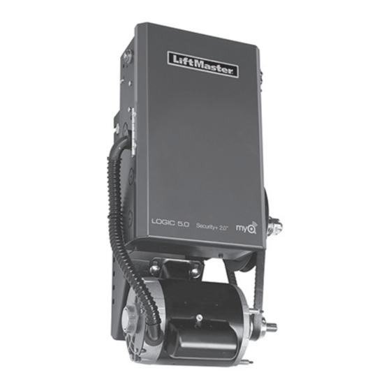
Logic 5.0 Commercial Door Operator
THIS PRODUCT IS TO BE INSTALLED AND SERVICED
BY A TRAINED DOOR SYSTEMS TECHNICIAN ONLY.
Operators are shipped in C2 operating mode.
Visit www.liftmaster.com to locate a professional installing
dealer in your area.
LiftMaster
300 Windsor Drive
Oak Brook, IL 60523
LiftMaster.com
USER'S GUIDE
®
Models T, APT, H, J, HJ, GH, and GT
CONTACT INFORMATION
WARNING: This product can expose you to chemicals
including lead, which are known to the State of
California to cause cancer or birth defects or other
reproductive harm. For more information go to
www.P65Warnings.ca.gov
2 YEAR WARRANTY
Serial #
Installation Date
Advertisement
Table of Contents

Related Manuals for Chamberlain T


Summary of Contents for Chamberlain T
- Page 1 Logic 5.0 Commercial Door Operator USER’S GUIDE ® Models T, APT, H, J, HJ, GH, and GT THIS PRODUCT IS TO BE INSTALLED AND SERVICED 2 YEAR WARRANTY BY A TRAINED DOOR SYSTEMS TECHNICIAN ONLY. Serial # Operators are shipped in C2 operating mode.
- Page 2 • Single phase operators provide (115V and 230V) • 3 phase operators provide (208/230V and 460V) • 575V operator CYCLE RATINGS STANDARD DUTY: Models T, APT, J, DJ, Up to 25 cycles/hr. at peak periods. H, DHJ, & SD Up to 80-90 cycles/day. HEAVY DUTY: Models GT, GH, &...
-
Page 3: Introduction To Programming
PROGRAMMING INTRODUCTION TO PROGRAMMING Many programmable functions require that a LiftMaster Entrapment Protection (LMEP) Device be installed in order to function. Before programming the logic board, set the operator’s open and LOGIC BOARD PUSH BUTTONS (OPEN, CLOSE, STOP) close limits. LEDs on the logic board are provided to assist setting Open, Close and Stop buttons are mounted directly on the logic the limits. -
Page 4: Determine And Set Wiring Type
PROGRAMMING DETERMINE AND SET WIRING TYPE Read the descriptions of the different wiring types to determine which setting will be correct for each application. Once the wiring type is determined, set the selector dial accordingly. LIFTMASTER MONITORED ENTRAPMENT PROTECTION (LMEP) LIFTMASTER MONITORED ENTRAPMENT PROTECTION (LMEP) DEVICE IS REQUIRED DEVICE IS RECOMMENDED... -
Page 5: Remote Controls
PROGRAMMING To prevent possible SEVERE INJURY or DEATH: • Activate door ONLY when it can be seen clearly, is properly • Install a LiftMaster Monitored Entrapment Protection (LMEP) adjusted and there are no obstructions to door travel. Device. • ALWAYS keep door in sight until completely closed. NEVER •... - Page 6 PROGRAMMING ® SETUP (OPTIONAL) For Smartphone App, tablet or PC control, LiftMaster MyQ Internet Gateway (model 828LM) is required. TO ERASE ALL MYQ DEVICES: 1. To enter programming mode, press and release the RADIO 1. Press and release the RADIO button on the logic board (the button on the logic board (the RADIO LED will light).
-
Page 7: Timer-To-Close
The STOP button WILL NOT deactivate the timer in the TS mode. To deactivate the timer for more than one cycle in T mode or in TS mode, attach a defeat switch to 11 and 12 (COMMON and TIMER DEFEAT). -
Page 8: Manual Release
ONLY when door is CLOSED. Weak or broken springs or unbalanced door could result in an open door falling rapidly and/or unexpectedly. EMERGENCY DISCONNECT SYSTEM MODEL GT AND T TO DISCONNECT DOOR FROM OPERATOR The door should be in the fully closed position if possible. - Page 9 MANUAL RELEASE EMERGENCY DISCONNECT SYSTEM MODEL H, GH, J, AND HJ To prevent possible SERIOUS INJURY from a moving chain: • DISCONNECT electric power to the operator BEFORE manually This operator has provisions for manually operating the door in operating your door. case of emergency or power failure.
- Page 10 TESTING Apply power to the operator. When power is applied to the operator, the following LED’s will illuminate: STOP, CLOSE, OPEN, LMEP, 24Vac, RADIO, DATA, To avoid SERIOUS personal INJURY or DEATH: TIMER ENABLE, OLS MID, SLS, CLS, and MAS. Once the power •...
-
Page 11: Troubleshooting
TROUBLESHOOTING To locate a dealer in your area visit us online at www.liftmaster.com. CONDITION POSSIBLE CAUSE OPERATOR WILL NOT RESPOND TO ANY No power Check circuit breaker. COMMANDS Accessory failure Verify photoelectric sensors are aligned. Possible component failure Contact your installing dealer. OPERATOR MAKES NOISE BUT DOOR Operator requires adjustment... - Page 12 ACCESSORIES ENTRAPMENT PROTECTION DEVICES MONITORED MONITORED CPS-U Dual-Sided Infrared Photo Eyes CPS3CARD Safety Interface Card • NEMA 1 general purpose enclosure. Plug-in Interface card enables use of a second set of • Dual-sided infrared sensors. monitored photo eyes or edge with a commercial door operator.
- Page 13 ACCESSORIES ® ACCESSORIES CONTROL STATIONS 02-101 1-Button Control Station: 828LM LiftMaster ® Internet Gateway Steel enclosure. Enables owners of Commercial Door Operators to open and close their doors and turn on/off lights in or around their facility using a smart phone or tablet computer from anywhere in the world.
- Page 14 ACCESSORIES MOUNTING BRACKETS ADDITIONAL CONTROL ACCESSORIES 10-12360 Heavy gauge steel bracket for vertical or horizontal 86LM (15' [4.6 m]) Antenna Extension Kit: mount on either front or top of coil on a rolling door. 86LMT (25' [7.6 m]) The antenna extension kit can be used with EXT-ANT Has a variety of mounting hole patterns compatible for maximum radio receiver range.
- Page 15 Actionneur de porte commerciale Logic 5.0 GUIDE DE L’UTILISATEUR ® Modèles T, APT, H, J, HJ, GH, et GT CE PRODUIT DOIT ÊTRE INSTALLÉ ET ENTRETENU GARANTIE DE 2 ANS SEULEMENT PAR UN TECHNICIEN FORMÉ EN No de série SYSTÈMES DE PORTE.
- Page 16 L’actionneur Logic 5.0 vous offre les fonctions utiles et fi ables de la version précédente en plus des nouvelles fonctions présentées ci-dessous : Technologie MyQ ® • Permet la surveillance sécurisée et la commande de l’actionneur par un téléphone intelligent, une tablette ou un ordinateur (nécessite une passerelle Internet LiftMaster). Security+ 2.0 ®...
-
Page 17: Introduction À La Programmation
MAS clignotera un code indiquant la version du micrologiciel. Si le cadran de réglage est en position DIAG, OPTN, ou PROG, le MAS ne fournira pas ce code. Après que le code ait été fourni, la DEL MAS s'éteindra. VUE D'ENSEMBLE DE LA CARTE LOGIQUE Bornier du câblage... -
Page 18: Détermination Et Configuration Du Type De Câblage
1. Des verrouillages externes peuvent être utilisés avec tous les modes de fermeture. fonctionnels. Si la minuterie de fermeture a été activée, le bouton ouvrir 2. Les dispositifs auxiliaires sont tout dispositifs qui ont seulement des et la commande radio peuvent recycler la minuterie. Le contacts secs. - Page 19 RADIO RADIO FSTS TÉLÉCOMMANDE À 3 BOUTONS POUR FONCTIONNER COMME UNE STATION DE CONTRÔLE SANS FIL À 3 BOUTONS REMARQUE : Cette caractéristique utilisera 3 des 90 canaux de mémoire du système de fermeture. Enfoncer et relâcher le bouton désiré...
- Page 20 1. Pressez et relâchez sur le bouton RADIO de la carte logique (le La passerelle Internet LiftMaster MyQ est exigée (modèle 828LM) voyant lumineux DEL RADIO clignotera). pour l’application pour téléphone intelligent, commande par 2. Pressez et maintenezenfoncé le bouton MAS pendant 5 secondes. tablette ou ordinateur.
-
Page 21: Minuterie De Fermeture
CLOSE (fermer) ou le bouton STOP (arrêt) pour arrêter la minuterie. (la DEL TIMER SET (réglage de minuterie) s’allume.) 7. Ramener le cadran de réglage au type de câblage désiré (T, TS ou FSTS). REMARQUE : Pour relire le réglage de minuterie de fermeture,... -
Page 22: Dégagement Manuel
SYSTÈME DE DÉCONNEXION D’URGENCE MODÈLES GT ET T POUR DÉCONNECTER LA PORTE DE L’OUVRE-PORTE La porte devrait être en position entièrement fermée si possible. - Page 23 Faire fonctionner la porte dans la direction désirée en tirant un côté ou l’autre de la chaîne de palan à boucle continue. La chaîne de déconnexion doit être dégager du garde-chaîne avant que la porte puisse fonctionner de nouveau de façon électrique.
- Page 24 DIAG, OPTN, ou PROG, le MAS ne fournira pas tous les autres modes. ce code. Après que le code ait été fourni, la DEL MAS s’éteindra. 5. Appuyer sur le bouton STOP (arrêter). (La porte devrait s’arrêter.) TEST DES CAPTEURS PHOTOÉLECTRIQUES...
-
Page 25: Dépannage
APPARENTE correctement, contacter le distributeur qui a installé le dispositif. FONCTIONNALITÉ RADIO La télécommande n’est pas PAS DE RÉPONSE Reportez-vous à la section PROGRAMMATION DES TÉLÉCOMMANDES. programmée Piles faible Remplacez la pile. LA TÉLÉCOMMANDE NE PEUT Piles faible Remplacez la pile. - Page 26 Carte d’interface de sécurité • Boîtier NEMA 1 tout usage La carte d’interface enfichable permet d’utiliser un • Cellules photoélectriques infrarouges à deux côtés deuxième jeu de cellules photoélectriques ou de • Pour utilisation intérieure chant surveillés avec un actionneur de porte •...
- Page 27 Boîtier en acier avec Système d’alerte d’entretien. 825LM Télécommande d’éclairage Permet de commander automatiquement votre éclairage à l’aide de l’ouvre-porte de garage, d’une télécommande Security+ 2.0 ® ou d’une passerelle Internet LiftMaster ® 02-110 Station de commande à clé : Se branche dans n’importe quelle prise de courant...
- Page 28 Carte de contact auxiliaire : AUXCARD La carte à option Contact auxiliaire a des contacts normalement ouverts et normalement fermés qui sont actionnés lorsque la porte est à l’arrêt, qu’elle s’ouvre ou qu’elle se ferme. © 2014, LiftMaster All Rights Reserved 01-39049B Tous droits réservés...
Need help?
Do you have a question about the T and is the answer not in the manual?
Questions and answers