
Related Manuals for Gaymar MEDI-THERM III


Summary of Contents for Gaymar MEDI-THERM III
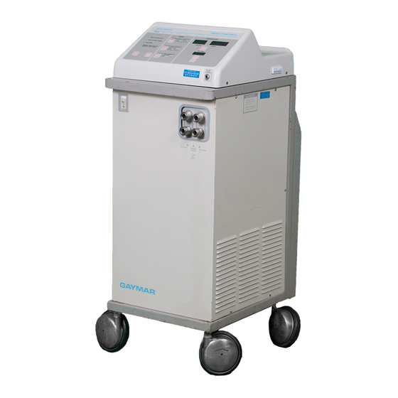
- Page 1 MEDI-THERM ® HYPER/HYPOTHERMIA MACHINE REF MTA7912 SERVICE MANUAL P/N 100909000 Rev B 11/09...
-
Page 2: Table Of Contents
Medi-Therm III System ......7 Medi-Therm III Control Panel ....9 Refer to section 2.0 of this Medi-Therm III Service Manual for Probe Check Well ........18 additional details. Functional Check/Inspection Form ..22 Initiating Service Mode 1 ...... -
Page 3: Safety Precautions
Electrical shock or damage to the machine can result. • Use only Gaymar probes (see Accessories, page 6) or equivalent YSI 400 series probes approved for use with medical devices in the Patient Probe jack. -
Page 4: Repair Policy
The Medi-Therm III Hyper/Hypothermia machine is warranted free of defects in material and workmanship for a period of two (2) years, under the terms and conditions of the Gaymar warranty in place at the time of purchase. The compressor portion of the machine carries a five year prorated warranty. -
Page 5: Specifications
MTA7912 Service Manual Specifications Specifications Physical Physical Specifications Model MTA7912 Dimensions 94 cm high x 48 cm deep x 36 cm wide Weight 76.3 kg (full); 68.6 kg (empty) Normal Reservoir Operating Volume 9.5 liters distilled water Operating Ambient Temperature Range 15.6°C to 32.2°C Power Loss Indicator Battery 8.4V NiMH... -
Page 6: Water Warm-Up Rate
± 0.2°C Display Resolution 0.1°C WATER TEMPERATURE Display Resolution 0.1°C PATIENT TEMPERATURE Controller Accuracy ± 0.8°C WATER TEMPERATURE Controller Accuracy ± 0.5°C PATIENT TEMPERATURE Flow* 60.6 liters per hour * Minimum flow rates through a full size Gaymar Hyper/Hypothermia Blanket... - Page 7 MTA7912 Service Manual Specifications Electrical Electrical Specifications Current Leakage, Earth Neutral closed 175 microamps maximum Neutral open 125 microamps maximum Current Leakage, Patient Probe Neutral closed 100 microamps maximum Neutral open 100 microamps maximum Voltage ~220 V to ~240 V ± 10% Frequency 50 Hz Power Consumption Capacity...
-
Page 8: Blankets/Body Wraps/Accessories
REF DHP810 O.R. Table and General Use (3 meters) for DP400CE Probe (64 cm x 163 cm) * These Gaymar probes, adapters, and hoses should be REF DHP812 Pediatric General Use used only with Gaymar Hyper/Hypothermia Machines. (56 cm x 84 cm) -
Page 9: Medi-Therm Iii System
Lift cover. Fill unit with Accepts patient probe plug connecting patient distilled water until green probe to machine. Use only Gaymar probes band on float is fully visible. or equivalent YSI 400 series probes approved for use with medical devices. -
Page 10: Operator Control Panel
The audible alarm will reactivate in REMOVE FROM USE NOW indicates 10 minutes if the condition persists. the Medi-Therm III machine has shut down due to a malfunction. Remove the machine from use. Contact qualified medical service personnel. -
Page 11: Medi-Therm Iii Control Panel
GRADUAL rate. PATIENT PROBE JACK— MONITOR ONLY— Insert only a Gaymar probe or an equivalent Connect patient probe, then use to YSI 400 series probe approved for use with monitor patient temperature. No medical devices. [located on front of machine]... -
Page 12: Theory Of Operation
MTA7912 Service Manual Theory of Operation, System Theory, Medi-Therm III Machine The Gaymar Medi-Therm III machine provides a means of regu- Whenever the machine is on, 9.5 liters of water are maintained lating patient temperature by supplying temperature-controlled cold in the cold water reservoir. A cold water reservoir probe... - Page 13 26-28, pp. 69-72 for the electrical schematics; figures 22-24, pp. 62-67 for component layouts Backup systems within the Medi-Therm III machine limit the and part designations; and figure 29, p. 73 for the system block temperature of water exiting the machine to specified ranges in diagram.
- Page 14 U49. At the same time, the resulting output voltage created by the current through the thermistor is presented to an Power enters the Medi-Therm III machine through circuit breaker amplifier circuit (U39 and associated components) via multiplexor CB1 to feed the refrigeration unit (through relay K1) and the U50.
- Page 15 MTA7912 Service Manual Theory of Operation • The patient display is driven by driver chip U6. The the probe presence switch within the patient probe jack J1, and main microcontroller interfaces to it via the data bus at the service mode button S3 on the control/display board. The addresses 0FFF4H, 0FFF5H, 0FFF6H, 0FFF7H.
- Page 16 Theory of Operation MTA7912 Service Manual When WARMING a patient in MODERATE or GRADUAL modes, microcontroller control circuits and the line voltage circuits. water temperatue is limited to a maximum of 41.0°C and a The heater, pump, hot solenoid valve, and cold solenoid valve minimum which is determined by the current CONTROL OPTION are individually controlled by the main microcontroller through selected (15°C below the patient temperature in MODERATE...
- Page 17 MTA7912 Service Manual Theory of Operation power supply circuits. Transformer T1 output is rectified and USE NOW LED, feeds driver U11 to light the ALERT LED, and filtered to generate unregulated positive voltage. Q1 is a linear feeds NOR gate U40 to drive the audible alarm located on the regulator with a nominal output of +5.0 volts.
- Page 18 Theory of Operation MTA7912 Service Manual mode is selected (or automatically every 60 seconds in standby mode) will cause the REMOVE FROM USE NOW condition to recur. 6.4.7.7 Other REMOVE FROM USE NOW Shutdown Conditions If during normal operation the main microcontroller senses internal problems, it will cause a machine shutdown condition as in 6.4.7.6.
-
Page 19: Functional Check, Safety Inspection, And Preventive Maintenance
Receiving Inspection Procedures 7.2.1 Machine Cleaning CONCEALED DAMAGE After unpacking the Medi-Therm III machine, inspect the machine C AUTION for concealed damage. Save all packing material and carefully describe or photograph the damage. Notify the carrier at once and ask for an inspection (in writing). Failure to do this within 15 days Users should not use cleaning or decontamination may result in loss of claim. -
Page 20: Probe Check Well
An Inspection Form is provided at the end of this section to REUSABLE PROBES facilitate and document the inspection process. Lower case letters For cleaning, disinfecting, and sterilizing reusable Gaymar probes preceding the subheadings within section 7.3 correspond to the (or equivalent YSI 400 series reusable probes), refer to the lines on the Inspection Form. - Page 21 The quick-disconnect fittings on the machine may become stiff and difficult to engage. If so, apply a silicone-base Plug in the Medi-Therm III machine and turn it on. Press and hold lubricant to the inside of the machine fittings and the outside the TEST LIGHTS button.
- Page 22 Functional Check and Safety Inspection MTA7912 Service Manual NOTE: If the unit has been completely drained, air can be Connect the test setup shown in figure 17A/B, p. 56. trapped in the pump causing flow to be decreased. Turn machine on. Set in BLANKET CONTROL mode. To clear the air, turn the unit off, wait approximately one minute, and start again from step 3.
- Page 23 Reset the RFU Code the supply hose from TPT9/flowmeter and allow water to The Medi-Therm III machine will retain the previously stored code. gravity drain into a container for approximately one minute. Before returning a machine to service, reset the RFU code to zero This will circulate cold water from the reservoir past the so that a previous code is not held in memory.
-
Page 24: Functional Check/Inspection Form
Functional Check and Safety Inspection Form MTA7912 Service Manual Medi-Therm III Hyper/Hypothermia Machine REF MTA7912 Functional Check / Inspection Form* Location ____________________________________________________ Serial number _________________________________________ Action Taken Item Action needed (Y/N) (Date / Initials) a. Condition of chassis b. Condition of attachment plug c. -
Page 25: Service Modes And Troubleshooting
RFU code to zero to avoid basing future troubleshooting decisions on an old code. Some troubleshooting and functional checks may be aided by using the Medi-Therm III machine’s service modes of operation. * RFU = REMOVE FROM USE NOW Service Modes... -
Page 26: Rfu Codes
Service Modes MTA7912 Service Manual Troubleshooting RFU Code Description Chart Reset code -- indicates no RFU condition recorded. None Measure water or reservoir probe value is out of the range 0°C to 50°C. Figure 10B 2, 3 Microprocessor system failure. Figure 10C Compensation resistor 1 (R12) is out of spec -- too high or open-circuited. - Page 27 MTA7912 Service Manual Service Modes Service Mode 1: To access: Press and hold S3 (see figure 8, p. 23) on the control/display board, then turn machine on. Uses: Verification of software version level. Last RFU code indication and RFU code reset. Verification of proper watchdog functioning (U34).
- Page 28 Service Modes MTA7912 Service Manual Service Mode 4: To access: Press DOWN while in service mode 3. Uses: To test the trip points of the backup system 1 over-temperature probe (RT3) and the backup system 2 (S2) thermostat. Description: PATIENT TEMPERATURE display is blank. ALERT LED flashes.
-
Page 29: N Troubleshooting Charts
MTA7912 Service Manual Troubleshooting Charts Troubleshooting Charts IMPORTANT Whenever possible, perform the Functional Check and Safety Inspection (see section 7.3) prior to troubleshooting the machine. REMOVE FROM USE NOW conditiion Enter Service Mode 1. Service Modes, section 8.1. Observe RFU code. See appropriate REMOVE FROM USE NOW... - Page 30 Troubleshooting Charts MTA7912 Service Manual RFU CODE 1 Insure integrity of the control/display board Run machine. If RFU condition (RFU code 1) Measured values to power supply board connections. reappears, unplug machine and measure from RT1 or RT2 are Insure integrity of base to resistance between pins 10 and 11 of J1 power supply board connections.
- Page 31 MTA7912 Service Manual Troubleshooting Charts RFU Code 2 RFU Code 3 RFU Code [—] RFU Code E RFU Code L Conversion Failure Conversion Failure CHECKSUM Failure RAMTEST Failure Main Microcontroller system failure. Contact your local dealer. Figure 10C—RFU Codes 2, 3, —, E, and L...
- Page 32 Troubleshooting Charts MTA7912 Service Manual RFU CODE 4 RFU CODE 5 Compensation resistor 1 Compensation resistor 1 (R12 on control/display (R12 on control/display board) reading is too high. board) reading is too low. Measure R12 resistance. Is it 816 ohms Replace R12.
- Page 33 MTA7912 Service Manual Troubleshooting Charts RFU CODE 6 RFU CODE 7 Compensation resistor 2 Compensation resistor 2 (R13 on control/display (R13 on control/display board) reading is too high. board) reading is too low. Measure R13 resistance. Is it 7320 ohms Replace R13.
- Page 34 Troubleshooting Charts MTA7912 Service Manual RFU CODE 8 Water temperature probe reading faulty. Insure integrity of control/display board to Is it power supply board connections. Insure Suspect temperature between 811 and integrity of base to power supply board measurement circuitry. 7355 ohms? connections.
- Page 35 MTA7912 Service Manual Troubleshooting Charts RFU CODE 9 Reservoir probe reading faulty. Insure integrity of control/display board to Is it power supply board connections. Insure Suspect temperature between 811 and integrity of base to power supply board measurement circuitry. 7355 ohms? connections.
- Page 36 Troubleshooting Charts MTA7912 Service Manual RFU CODE P Main Microcontroller detected that Backup System 1 not functioning. Insure integrity of alarm/backup board connections at P11 & P12. Repair/replace alarm/backup board. Figure 10H—RFU Code P...
- Page 37 MTA7912 Service Manual Troubleshooting Charts PUMP MOTOR NOT RUNNING Verify unit is in PATIENT CONTROL or BLANKET CONTROL modes. Line voltage at Repair/replace terminals 5 and 8 pump. of TB1? Line Suspect voltage at base-to-power supply input pulled board connection. low? Repair.
- Page 38 Troubleshooting Charts MTA7912 Service Manual Machine doesn't turn on when circuit breaker is in ON position. Check that power cord is secure at both the power inlet module and the receptacle. Check that the cord retainer is in place. Check for blown step-down transformer fuse (F1) inside machine.
- Page 39 MTA7912 Service Manual Troubleshooting Charts [This page has been intentionally left blank]...
- Page 40 Troubleshooting Charts MTA7912 Service Manual Figure 10K—RFU Code H...
- Page 41 MTA7912 Service Manual Troubleshooting Charts...
- Page 42 Troubleshooting Charts MTA7912 Service Manual Check Adjust setpoint to CHECK WATER Check/suspect hot solenoid SV2 insure WARMING FLOW alert is on. solenoids. (it should be LED is on. energized). Is a steel object attracted to center top of Are hoses the valve? Connect connected properly...
- Page 43 MTA7912 Service Manual Troubleshooting Charts Line Line Is pin 9 Suspect voltage at terminals voltage at optocoupler ref to pin 10 control/display board. 2 and 3 of output of U7 input pulled of U51 Repair/replace. TB1? low? 0 VDC? Suspect Suspect Disconnect board-to-board...
- Page 44 Troubleshooting Charts MTA7912 Service Manual Select BLANKET BLANKET/BODY WRAP Connect test setup CONTROL mode. If measured temperature WON'T HEAT IN PATIENT water temperature as shown in Adjust setpoint to 41°C. contradicts this, CONTROL or BLANKET display within 1°C figure 17. Allow machine time to heat suspect RT2.
- Page 45 MTA7912 Service Manual Troubleshooting Charts NOTES: The line voltage measured should be the same as that measured across terminals 4 and 3 of TB1. (There may be residual voltage between terminals 2 and 3 or terminals 1 and 3 of TB1 when the circuitry is in the OFF state because of the solenoid valve construction and circuit configuration.
- Page 46 MTA7912 Service Manual Troubleshooting Charts Figure 10N—Blanket/Body Wrap Will Not Cool (sheet 1 of 2)
- Page 47 MTA7912 Service Manual...
- Page 48 Troubleshooting Charts MTA7912 Service Manual Figure 10N—Blanket/Body Wrap Will Not Cool (sheet 2 of 2)
-
Page 49: Repair Procedures
Servicing and/or repair of the refrigeration system the unit is connected to a blanket or body wrap, should be performed in compliance with applicable and the Medi-Therm III has been set to 4°C in regulations. BLANKET CONTROL mode; the reservoir water temperature is 4.4°C; and, 9.1.1... - Page 50 Repair Procedures MTA7912 Service Manual Replacing the Power Supply Board Connect the 7-conductor cable harness connector P12 to the alarm/backup board. C AUTION Perform the Functional Check and Safety Inspection Wear a static control device connected to the chassis (section 7.3). ground to prevent electrostatic discharge.
-
Page 51: Connecting Terminal Block Wires
MTA7912 Service Manual Repair Procedures Replacing the Control/Display Board Connect the 7-conductor cable harness connector P12 to the alarm/backup board. C AUTION Connect the 26-conductor cable harness connector P1 to the alarm/backup board. Wear a static control device connected to the chassis Perform the Functional Check and Safety Inspection ground to prevent electrostatic discharge. - Page 52 Repair Procedures MTA7912 Service Manual Install the standoffs through the other four (4) holes. C AUTION Insert patient probe assembly into mounting hole and fasten with hex nut. Insure patient probe assembly is oriented so Always use thermal grease on thermostats. that the bevelled corner of the probe assembly is positioned Failure to use thermal grease could raise trip as shown in figure 20, p.
-
Page 53: Flow Switch
MTA7912 Service Manual Repair Procedures Replacement Parts For base replacement parts information, see figure 19 (pp. 58-59). For head replacement parts information, see figure 20 (p. 60). Repairs should only be performed by qualified personnel familiar with repair practices for servicing medical devices. Shipping/Repackaging Instructions C AUTION Failure to install compressor shipping braces... -
Page 54: Service Information
Service Information MTA7912 Service Manual 10.0 Service Information PATIENT PROBE, WATER TEMPERATURE PROBE (RT2), RESERVOIR PROBE (RT1), AND OVER-TEMPERATURE PROBE (RT3) TEMPERATURE RESISTANCE TEMPERATURE RESISTANCE TEMPERATURE RESISTANCE (°C) (OHMS) (°C) (OHMS) 7355 2156 6989 2064 6644 1977 6319 1894 6011 1815 5719 1739... -
Page 55: Circuit Boards/Connectors (Head)
MTA7912 Service Manual Service Information Ground harness P4 at J4A Patient probe assembly P5 at J3 P2 at J2 P3 at J4 P12 at J1 Cable Control/ assembly display 26-conductor board P9 at J2 P11 at J4 RT3 Indicator Power supply board Alarm... -
Page 56: B Heating Flow; Cooling Flow
Service Information MTA7912 Service Manual When the Medi-Therm III machine is heating, water flows in the path shown below. Cold Water Reservoir Machine - Blanket/ Overflow Body Wrap Connections Air Vent Water RETURN Temp. Hot Water Probe Reservoir Heater (RT2) -
Page 57: Refrigeration Flow Diagram
MTA7912 Service Manual Service Information Figure 16—Refrigeration flow diagram... -
Page 58: B Test Setup; Test Setup (Alternate)
Service Information MTA7912 Service Manual Full size Blanket on an insulating surface Thermometer DBK35CE Connector Hose SUPPLY RETURN TPT9 Tester ® (Must always be installed in the SUPPLY line before blanket. Do not install in the RETURN line.) Figure 17A—Test setup [using TPT9 Tester and Thermometer] Figure 17B—Test setup [using alternate test equipment]... -
Page 59: Machine Disassembly
P7 P6 Chassis Ground FOR GROUNDING PURPOSES: Two (2) star washers are required with these two screws. REMOVING WRAPAROUND: Flex side panels of wraparound out slightly as indicated by GAYMAR ® arrows. Wraparound Inside view of chassis wraparound Figure 18—Machine disassembly... -
Page 60: Parts Diagram (Base), Parts List
Service Information MTA7912 Service Manual Replacement: Original: 2 pieces 1 piece Figure 19—Parts Diagram (Base) - Page 61 MTA7912 Service Manual Service Information PART PART ITEM DESCRIPTION ITEM DESCRIPTION NUMBER NUMBER Power Cord See below Thermostat (S2) Kit 78191-000 EMI Filter Replacement Kit 78197-000 Temperature Probe Assembly (RT2) Kit 77737-000 Power Cord Strap 03791-000 Thermostat (S1) 78193-000 Isolation Transformer (T2) 78186-000 Transformer (T1) Kit 78182-000...
-
Page 62: Parts Diagram (Head), Parts List
Service Information MTA7912 Service Manual MACHINE STATUS 36-51 ® ® PART PART ITEM DESCRIPTION ITEM DESCRIPTION NUMBER NUMBER Ratchet Fastener 91428-002 PC Board, Power 10528-001 Cable Clip 90228-005 Stem (includes items 58 and 59) 77760-000 Rating Label 100434-000 Fill Label 10349-000 Operating Instruction Card Assembly 100449-000... -
Page 63: Thermostat Wiring Diagram
MTA7912 Service Manual Service Information Figure 21—Thermostat Wiring Diagram... -
Page 64: Control/Display Board, Parts List
Control/Display Board MTA7912 Service Manual Figure 22—Control/Display Board... - Page 65 MTA7912 Service Manual Control/Display Board Designator Description Designator Description Resistor, 4.7K, 1/4W, 5% 90092-065 C2, C4, C6 R19-R21 Resistor, 2.7K, 1/4W, 5% 90092-059 C9-C14, C18 RN1-RN3, RN5 Resistor Network, 27 ohm bussed 91248-001 C23-C25, C27 C28, C30, C31 Capacitor, 0.1 μ F, 50V 90701-169 Resistor Network, 47K isolated 91248-018...
-
Page 66: Power Supply Board, Parts List
Power Supply Board MTA7912 Service Manual Figure 23—Power Supply Board... - Page 67 MTA7912 Service Manual Power Supply Board Designator Description Designator Description C1, C2 Capacitor, 1000 μ F, 35V 90701-080 Q10, Q11 Transistor, 2N3904 90868-015 C3, C12, C16 Capacitor, 0.1 F, 50V 90701-169 Transistor, 2N6727 90868-030 Capacitor, 390 F, 40V 90701-079 R1, R3 Resistor, 2.00K, 1/8W, 1% 90092-364 Resistor, 2.80K, 1/8W, 1%...
-
Page 68: Alarm/Backup Board, Parts List
Alarm/Backup Board MTA7912 Service Manual Figure 24—Alarm/Backup Board... - Page 69 MTA7912 Service Manual Alarm/Backup Board Designator Description Designator Description R1, R7, R13 Resistor, 4.7K, 1/4W, 5% 90092-065 See 7.3e Rechargeable battery, 9V (page 18) R2, R6, R10 Resistor, 10K, 1/4W, 5% 90092-073 Capacitor, 470 μ F, 25V 90701-061 Resistor, 470 ohm, 1/4W, 5% 90092-041 C2, C3 Capacitor, 0.1 F, 50V...
-
Page 70: Wiring Diagram [Foldout]
MTA7912 Service Manual... -
Page 71: Power Supply Board Schematic, 1 Of 4 [Foldout]
MTA7912 Service Manual... -
Page 72: Control Display Board Schematic, 2 Of 4 [Foldout]
MTA7912 Service Manual GAYMAR INDUSTRIES, INC. 10 Centre Drive Orchard Park, NY 14127-2295 Phone: +1 716 662-8636 Fax: +1 716 662-0730...
Need help?
Do you have a question about the MEDI-THERM III and is the answer not in the manual?
Questions and answers