
Related Manuals for Gaymar MEDI-THERM III


Summary of Contents for Gaymar MEDI-THERM III
- Page 1 ® MEDI-THERM HYPER/HYPOTHERMIA MACHINE MTA6900 SERIES LISTED 303L U. S. PATENT NO. 6,517,510 CANADIAN PATENT NO. 2,411,539 SERVICE MANUAL P/N 12147-000 1/04...
- Page 2 Failure to do this within 15 days may result in loss of claim. IMPORTANT Before operating the Medi-Therm III machine, remove Refer to section 7.0 of this Medi-Therm III Service Manual for the compressor shipping braces. See p. 88, figure B. additional details. OPERATING INSTRUCTIONS For information on operating the Medi-Therm III machine, refer to the Medi-Therm III Operator's Manual.
-
Page 3: Table Of Contents
SERVICE MANUAL CONTENTS Medi-Therm ® CONTENTS Section Description Page PATIENT SAFETY ..................1 MACHINE PRECAUTIONS ............... 3 REPAIR POLICY ................... 4 In-Warranty Repairs ................4 Out-of-Warranty Repairs ..............4 SPECIFICATIONS ..................5 Physical Specifications ................5 Thermal Specifications ................. 5 Electrical Specifications ................ - Page 4 ILLUSTRATIONS Figure Description Page Typical Warm-up Rate ................. 6 Typical Cooldown Rate ................. 6 Medi-Therm III System ................. 8 MT590 Test Tool ................... 24 Initiating Service Mode 1 ................35 6A/6L Troubleshooting Charts ................38 Accessing RFU Codes ................... 38 RFU Code 1 ....................
-
Page 5: Patient Safety
Use the Medi-Therm III Hyper/Hypothermia machine only under the direction of a physician. Review the following precautions and procedures prior to each application: DANGER Do not use the Medi-Therm III machine in the presence of flammable anesthetics. Risk of explosion can result. WARNING •... - Page 6 PATIENT SAFETY SERVICE MANUAL ® Medi-Therm PATIENT SAFETY WARNING (continued) • Avoid placing additional heat sources between the patient and blanket. Skin damage can result. Heat applied by the blanket can result in a rise in skin temperature at the areas of contact. The additional heat rise due to electrosurgical currents flowing to the dispersive electrode could be sufficient to cause tissue injury.
-
Page 7: Machine Precautions
Repairs should be performed only by qualified personnel such as certified biomedical electronics technicians or certified clinical engineers familiar with repair practices for servicing medical devices, and in accordance with the Medi-Therm III Service Manual. Improper repair may result in death or serious injury, equipment damage, or malfunction. -
Page 8: Repair Policy
(2) years, under the terms and conditions of the Gaymar warranty in place at the time of purchase. The compressor portion of the machine carries a five (5) year prorated warranty. The full warranty is available from Gaymar upon request. -
Page 9: Specifications
SERVICE MANUAL SPECIFICATIONS ® Medi-Therm SPECIFICATIONS PHYSICAL SPECIFICATIONS . n i . n i . n i ; ) l l ; ) l l t i l i t s e l l F ° F ° ° 6 °... -
Page 10: Electrical Specifications
SPECIFICATIONS SERVICE MANUAL ® Medi-Therm THERMAL SPECIFICATIONS (cont'd) WARM-UP RATE (typical) COOLDOWN RATE (typical) Time (minutes) Time (minutes) Figure 1—Typical warm-up rate Figure 2—Typical cooldown rate (with full size blanket) (with full size blanket) ELECTRICAL SPECIFICATIONS ± ° 5 ± F °... -
Page 11: Probe Information
Patient probe—Skin surface (10' [3.0 meters] long); YSI 400 series type Probe Adaptor • ADP10B Reusable adaptor cable for DP400: connects Gaymar disposable probe to Gaymar or Cincinnati Sub-Zero control unit. WARNING Some manufacturer’s patient probes may contain compensation resistors in series with YSI 400 series thermistors. -
Page 12: Medi-Therm Iii System
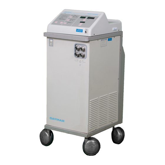
® MEDI-THERM III SYSTEM SERVICE MANUAL ® Medi-Therm Figure 3—Medi-Therm III System... -
Page 13: Theory Of Operations
The feedback for control purposes depends upon the machine's operating mode. The Medi-Therm III machine may be operated in one of three operating modes: • In MANUAL mode, the operator sets the desired blanket temperature. A... - Page 14 Hot and cold solenoid valves regulate the flow path by directing water returning from the blanket to either the hot or cold water reservoir. Regulating MEDI-THERM III the flow path controls the temperature of water pumped to the blanket. The MACHINE (continued) microcontroller controls solenoid valve operation.
-
Page 15: Interconnections
24, p. 87 for the system block diagram. CONTROL/DISPLAY BOARD AND POWER SUPPLY BOARD The Medi-Therm III machine uses two printed circuit boards (see figure 8, p. 67): • The control/display board contains the microcontroller circuits, the display circuits, and all other low voltage control circuits. -
Page 16: Power Supply
22–23, pp. 85–86 for component layouts and part designations; and figure 24, p. 87 for the system block diagram. Power enters the Medi-Therm III machine through circuit breaker CB1 to feed the refrigeration unit through relay K1. It also then enters the power supply... - Page 17 SERVICE MANUAL THEORY OF OPERATION ® Medi-Therm 6.4.1 THERMISTOR Temperature measurement is achieved using 400 series thermistor beads located in the blanket water path (blanket water probe RT2), the cold water reservoir OUTPUT (cold water reservoir probe RT1), and in the patient via the patient probe jack J1. MEASUREMENT Under microcontroller U37 control, each of the three beads is connected to the current source circuitry (U38 and associated components) by a demultiplexor...
- Page 18 THEORY OF OPERATION SERVICE MANUAL ® Medi-Therm 6.4.3 DISPLAY UPDATE All alarm and status indicators are lit by LED bars driven by inverter/driver IC’s: (continued) • The alarm latch U53 is the interface between the microcontroller and the ALERT, ADD WATER, CHECK PROBE, CHECK FLOW, REMOVE FROM USE NOW / MACHINE SHUTDOWN, SELECT, °F and °C drivers via the data bus at address 0FFBFH.
- Page 19 SERVICE MANUAL THEORY OF OPERATION ® Medi-Therm 6.4.5 BLANKET / PATIENT If the machine is in MANUAL mode, the blanket water temperature as sensed by the blanket water probe is used as the feedback signal for controlling the water TEMPERATURE temperature to the MANUAL mode set point temperature.
- Page 20 THEORY OF OPERATION SERVICE MANUAL ® Medi-Therm Pin 11 of U51 on the control/display board and U8 and Q9 of the power supply board control the cold solenoid valve while pin 9 of U51 on the control/display board and U7 and Q8 of the power supply board control the hot solenoid valve. Pin 8 of U51 on the control/display board and U2 and Q4 of the power supply board control the circulating pump.
- Page 21 SERVICE MANUAL THEORY OF OPERATION ® Medi-Therm 6.4.7 BACK-UP WATER goes into a shutdown condition it also sends an output signal from port pin P3.4, through U40 of the control/display board, to command, via Q11, U4, and U6 on TEMPERATURE the power supply board, a REMOVE FROM USE NOW / MACHINE SHUTDOWN LIMITING (continued) condition.
-
Page 22: Functional Check, Safety Inspection, Preventive Maintenance
Medi-Therm FUNCTIONAL CHECK, SAFETY INSPECTION, AND PREVENTIVE MAINTENANCE Concealed Damage RECEIVING After unpacking the Medi-Therm III machine, inspect the machine for concealed INSPECTION damage. Save all packing material and carefully describe or photograph the PROCEDURES damage. Notify the carrier at once and ask for an inspection (in writing). Failure to do this within 15 days may result in loss of claim. - Page 23 SERVICE MANUAL CLEANING PROCEDURES ® Medi-Therm CLEANING Pump PROCEDURES Pump motor should be oiled once a year with 3-4 drops of general purpose motor oil in the locations identified on the pump label. (continued) Panel Exterior Clean the control panel and panel exterior with a cloth dampened with isopropyl alcohol.
-
Page 24: Functional Check And Safety Inspection
• Current Leakage Tester • Static Control Wrist Strap The GAYMAR MT590 Test Tool is a dedicated test tool available from Gaymar Industries. This tool was designed to allow for more convenient and safer testing of the high temp backup thermostats by eliminating the need to remove the lower wraparound cover and avoiding the use of a shorting jumper that could be accidentally left inside the machine. - Page 25 SERVICE MANUAL FUNCTIONAL CHECK AND ® Medi-Therm SAFETY INSPECTION 7.3 FUNCTIONAL CHECK DANGER AND SAFETY Disconnect power before servicing unit. Risk of electrical shock. INSPECTION (continued) Follow the following procedures carefully, paying particular attention to test setups. Any deviation from the setups, procedures, or test equipment may result in incorrect or misleading results.
- Page 26 7.3 FUNCTIONAL CHECK e) Condition of Lights and Alarm AND SAFETY Plug in the Medi-Therm III machine and turn it on. Press and hold the TEST LIGHTS button. The right and left halves of the display panel should INSPECTION light and blank alternately (along with the audible alarm). The four status...
- Page 27 SERVICE MANUAL FUNCTIONAL CHECK AND ® Medi-Therm SAFETY INSPECTION 7.3 FUNCTIONAL CHECK h) Cold Water Reservoir Controller AND SAFETY To check the cold water reservoir controller, perform the following: INSPECTION Fill machine with distilled water until green band on float stem is (continued) fully visible.
-
Page 28: Mt590 Test Tool
INSPECTION temperature backup thermostats. Steps 1-15, pp. 24-26, should be (continued) followed when a Gaymar MT590 Test Tool is available. For those facilities not having access to an MT590, follow steps 1A-20A, pp. 27-28. FROM MT590 TEST TOOL TO J1 ON POWER SUPPLY BOARD IN HEAD ®... -
Page 29: High Temperature Limits
SERVICE MANUAL FUNCTIONAL CHECK AND ® Medi-Therm SAFETY INSPECTION Unplug the power cord. 7.3 FUNCTIONAL CHECK AND SAFETY Connect the test setup as shown in figure 13, p. 74. INSPECTION Connect MT590 Test Tool as shown in figure 4. Connect P7 (base) to J1 (MT590). - Page 30 FUNCTIONAL CHECK AND SERVICE MANUAL ® SAFETY INSPECTION Medi-Therm 7.3 FUNCTIONAL CHECK j) High Temperature Backup Thermostat Trip Temperatures AND SAFETY [MT590 Test Tool Procedure, cont'd.] INSPECTION 12. Place both switches S2 and S3 in the bypass position. Turn the machine (continued) off, then turn the machine on and select MANUAL mode.
- Page 31 SERVICE MANUAL FUNCTIONAL CHECK AND ® Medi-Therm SAFETY INSPECTION 7.3 FUNCTIONAL CHECK j) High Temperature Backup Thermostat Trip Temperatures AND SAFETY [Alternate Shorting Jumper Procedure] INSPECTION To measure trip points of the high temperature backup thermostats if you (continued) do not have access to an MT590 Test Tool, perform the following steps 1A-20A.
- Page 32 FUNCTIONAL CHECK AND SERVICE MANUAL ® SAFETY INSPECTION Medi-Therm 7.3 FUNCTIONAL CHECK j) High Temperature Backup Thermostat Trip Temperatures AND SAFETY [Alternate Shorting Jumper Procedure, cont'd.] INSPECTION NOTE: If this is the second time the thermostat has tripped (continued) (i.e., if you have previously completed steps 12A to 18A), proceed to step 19A.
- Page 33 SERVICE MANUAL FUNCTIONAL CHECK AND ® Medi-Therm SAFETY INSPECTION 7.3 FUNCTIONAL CHECK k) Thermostat Verification Test AND SAFETY WARNING INSPECTION (continued) Verify that the high temperature backup thermostats independently shut down the machine. Incorrect operation of these thermostats may result in death or serious injury.
- Page 34 FUNCTIONAL CHECK AND SERVICE MANUAL ® SAFETY INSPECTION Medi-Therm 7.3 FUNCTIONAL CHECK l) Patient Temperature Display Test AND SAFETY To check the patient temperature display, perform the following: INSPECTION Fill machine with distilled water until green band on float stem is (continued) fully visible.
- Page 35 Gaymar's Technical Service Department. p) Reset the RFU Code The Medi-Therm III machine will retain the previously stored code. Before returning a machine to service, reset the RFU code to zero so that a previous code is not held in memory.
- Page 36 WARNING Verify that the MT590 Test Tool or any installed shorting jumpers have been removed before returning the Medi-Therm III to service. Failure to do so may result in death or serious injury.
-
Page 37: Inspection Form
SERVICE MANUAL INSPECTION FORM ® Medi-Therm INSPECTION FORM I I I i t i ° ° ° ° ° ° ° ° ° ° ° ° ° ° ° ° ° ° ° ° ° ° f i r ° ±... -
Page 38: Troubleshooting & Service Modes
SERVICE MODES Medi-Therm TROUBLESHOOTING Some troubleshooting and functional checks may be aided by using the Medi-Therm III machine’s service modes of operation. AND SERVICE MODES SERVICE MODES All service modes are entered from service mode I by pressing the appropriate digital control panel button within 10 seconds of entry into service mode 1. -
Page 39: Rfu Error Codes
SERVICE MANUAL SERVICE MODES ® Medi-Therm SERVICE MODES (continued) SERVICE BUTTON S3 ON CONTROL/DISPLAY BOARD Figure 5—Initiating service mode 1 — † t i d F ° F ° ° 0 ° 0 r c i l l o u l i t s i –... -
Page 40: Service Modes
SERVICE MODES SERVICE MANUAL ® Medi-Therm Table 3 - Service Modes Service Mode 1: To access Press and hold S3 (see figure 5, p. 35) on the control/display board, then turn machine on. Uses • Verification of software version level. •... - Page 41 SERVICE MANUAL SERVICE MODES ® Medi-Therm Table 3 - Service Modes (continued) Service Mode 3: To access Press AUTO button while in service mode 1. Uses To prewarm the machine for testing of high temperature thermostat S2 and S3 trip points. Description •...
-
Page 42: Troubleshooting Charts
TROUBLESHOOTING CHARTS SERVICE MANUAL ® Medi-Therm TROUBLESHOOTING CHARTS IMPORTANT Whenever possible, perform the FUNCTIONAL CHECK AND SAFETY INSPECTION (see section 7.3) prior to troubleshooting machine. Figure 6A—Accessing RFU codes... -
Page 43: Rfu Code 1
SERVICE MANUAL TROUBLESHOOTING CHARTS ® Medi-Therm RFU CODE 1 Run machine. If RFU condition (RFU Insure integrity of the control/display Measured values code 1) reappears, unplug machine from RT1 or RT2 board to power supply board and measure resistance between pins are not within connections. -
Page 44: Rfu Codes 2, 3, - , E, And L
TROUBLESHOOTING CHARTS SERVICE MANUAL ® Medi-Therm Figure 6C—RFU Codes 2, 3, – , E, and L... -
Page 45: Rfu Codes 4, 5
SERVICE MANUAL TROUBLESHOOTING CHARTS ® Medi-Therm RFU CODE 4 RFU CODE 5 Compensation resistor 1 Compensation resistor 1 (R12 on (R12 on control/display board) control/display board) reading is too high reading is too low Measure R12 resistance. Is it 816 ohms Replace R12. -
Page 46: Rfu Codes 6, 7
TROUBLESHOOTING CHARTS SERVICE MANUAL ® Medi-Therm RFU CODE 6 RFU CODE 7 Compensation resistor 2 Compensation resistor 2 (R13 on (R13 on control/display control/display board) board) reading is too low . reading is too high. Measure R13 resistance. Is it 7320 ohms Replace R13. -
Page 47: Rfu Code 8
SERVICE MANUAL TROUBLESHOOTING CHARTS ® Medi-Therm RFU CODE 8 Blanket probe reading faulty Insure integrity of control/display Is it Suspect board to power supply board between temperature connections. Insure integrity of 811 and 7355 measurement base to power supply board ohms circuitry. -
Page 48: Rfu Code 9
TROUBLESHOOTING CHARTS SERVICE MANUAL ® Medi-Therm RFU CODE 9 Reservoir probe reading faulty Insure integrity of control/display Is it Suspect board to power supply board between temperature connections. Insure integrity of 811 and 7355 measurement base to power supply board ohms circuitry. - Page 49 TROUBLESHOOTING CHARTS SERVICE MANUAL ® Medi-Therm [This page has been intentionally left blank.]...
-
Page 51: Rfu Code H
RFU condition thermostat out Function T est. reappear? of spec Is S1 thermostat out of spec Does TPT9 read Replace less than 37.4°F thermostat. (3°C) ? Replace S1 Possible faulty control system or temperature measurement circuitry. Call Gaymar Technical Services. -
Page 52: Check Water Flow Alert Is On
TROUBLESHOOTING CHARTS SERVICE MANUAL ® Medi-Therm Figure 6I—Check Water Flow Alert is On, Page 1 of 2... -
Page 53: Check Water Flow Alert Is On
SERVICE MANUAL TROUBLESHOOTING CHARTS ® Medi-Therm Figure 6I—Check Water Flow Alert is On, Page 2 of 2... -
Page 54: Pump Motor Not Running
SERVICE MANUAL TROUBLESHOOTING CHARTS ® Medi-Therm PUMP MOTOR NOT RUNNING Verify unit is in AUTO or MANUAL modes. Line voltage at Repair/ terminals 6 replace and 8 of pump. TB1? Suspect Line base-to-power voltage at supply board output of connection. Repair. - Page 55 SERVICE MANUAL TROUBLESHOOTING CHARTS ® Medi-Therm [This page has been intentionally left blank.]...
-
Page 56: Blanket Won't Heat In Auto Or Manual Mode
SERVICE MANUAL TROUBLESHOOTING CHARTS ® Medi-Therm Figure 6K—Blanket Won't Heat in Auto or Manual Mode, Page 1 of 2... -
Page 57: Blanket Won't Heat In Auto Or Manual Mode
SERVICE MANUAL TROUBLESHOOTING CHARTS ® Medi-Therm Figure 6K—Blanket Won't Heat in Auto or Manual Mode, Page 2 of 2... -
Page 58: Blanket Will Not Cool
Select MANUAL mode. Connect test setup Adjust setpoint to Will reservoir BLANKET WILL as shown in figure blanket display 4°C (39.2°F). temperature reach compressor within 1.8°F (1°C) 13 (but don’t use Allow machine time NOT COOL 42.8°F (6°C) or of setpoint the blanket). - Page 59 Check cold Hot solenoid SV2 Line Suspect Line solenoid SV1 may be stuck voltage at base-to-power voltage at (it should terminals 11 open or cold supply board output of be on). and 8 of connection. solenoid SV1 TB1? Repair. stuck closed. Line Suspect Disassemble...
-
Page 60: Blanket Will Not Cool
TROUBLESHOOTING CHARTS SERVICE MANUAL ® Medi-Therm Figure 6L—Blanket Will Not Cool, Page 3 of 3... -
Page 61: Repair Procedures
Using other refrigerants or oils will damage the compressor. • The Medi-Therm III R-134a system uses a polyol ester oil for lubrication because conventional mineral oils do not provide sufficient lubricity and miscibility. R-134a refrigerant and polyol ester oil are highly susceptible to moisture absorption (more so than mineral oil). - Page 62 123 to 137 psi, under the following conditions: the unit’s wraparound is removed; the ambient temperature is 72°F (22.2°C); the unit is connected to a blanket, and the Medi-Therm III has been set to 39.2°F (4°C) in manual mode; the reservoir water temperature is 40°F (4.4°C); and, the pressure check is performed with a gauge manifold connected to the system with flexible hoses.
-
Page 63: Replacing The Power Supply Board
SERVICE MANUAL REPAIR PROCEDURES ® Medi-Therm REPLACING THE CAUTION POWER SUPPLY BOARD Wear a static control device connected to the chassis ground to prevent electrostatic discharge. (See figure 5, p. 35.) Electrostatic discharge can damage circuitry on PC boards. The following procedures describe replacement of the power supply board. A digital voltmeter is required. -
Page 64: Replacing The Control/Display Board
REPAIR PROCEDURES SERVICE MANUAL ® Medi-Therm REPLACING THE CAUTION CONTROL/DISPLAY Wear a static control device connected to the chassis ground to prevent BOARD electrostatic discharge. (See figure 5, p. 35.) Electrostatic discharge can damage circuitry on PC boards. Control/Display Board Removal (refer to figure 8, p. 67): Unplug the power cord. -
Page 65: Replacing The Top Cover
SERVICE MANUAL REPAIR PROCEDURES ® Medi-Therm Move the 26-conductor cable harness and EMI filter assembly over the standoffs. Insert two board screws through the transformer cable retaining clips on the transformer cable and mount one through the corner EMI filter assembly hole and into the standoff. Mount the other to the standoff along the board's longer edge. -
Page 66: Replacing Thermostats
(Wakefield Engineering; Wakefield, Massachusetts) CAUTION Always use thermal grease on thermostats for MTA6900 series Medi-Therm III units. Failure to use thermal grease could raise trip points above the acceptable range. Reconnect spade lugs to terminals. Refer to figures 17, p. 79 to ensure thermostat is connected correctly. -
Page 67: Cleaning The Flow Switch
SERVICE MANUAL REPAIR PROCEDURES ® Medi-Therm CLEANING THE To clean the flow switch (see figure 7 below and figure 15, pp. 76-77): FLOW SWITCH Remove nuts (item A) and remove assembly. Loosen hose clamps (items B and C) and remove hoses. Remove barbed adapters (item D). -
Page 68: Replacement Parts
(See p. 88, figure B.) See figure 25, p. 88 for complete repackaging instructions to ship the Medi-Therm III machine back to Gaymar or to a qualified Service Center. If you do not have the original packing materials, please contact Gaymar's Technical Service Department and a complete Customer Return Kit will be sent to you. -
Page 69: Reference Tables
SERVICE MANUAL REFERENCE TABLES ® Medi-Therm 10.0 REFERENCE TABLES 10.1 CELSIUS-FAHRENHEIT CONVERSION °C °F °C °F °C °F °C °F 32.0 11.5 52.7 23.0 73.4 34.5 94.1 32.9 12.0 53.6 23.5 74.3 35.0 95.0 33.8 12.5 54.5 24.0 75.2 35.5 95.9 34.7 13.0... -
Page 70: Temperature Vs. Resistance
REFERENCE TABLES SERVICE MANUAL ® Medi-Therm 10.2 TEMPERATURE vs. RESISTANCE PATIENT PROBE, BLANKET WATER PROBE (RT2), AND RESERVOIR PROBE (RT1) TEMPERATURE RESISTANCE TEMPERATURE RESISTANCE TEMPERATURE RESISTANCE °C °F (OHMS) °C °F (OHMS) 32.0 7355 78.8 2156 33.8 6989 80.6 2064 35.6 6644 82.4... -
Page 71: Service Information
SERVICE INFORMATION SERVICE MANUAL ® Medi-Therm 11.0 SERVICE INFORMATION GROUND HARNESS P4 at J4 P5 at J3 PATIENT PROBE ASSEMBLY P2 at J2 P3 at J4 CONTROL DISPLAY BOARD POWER SUPPLY BOARD CABLE ASSEMBLY 26 CONDUCTOR P6 at J2 P1 at J1 GROUND CHASSIS P7 at J1... -
Page 72: Operator Controls/Indicators
SERVICE INFORMATION SERVICE MANUAL ® Medi-Therm Figure 9A—Operator Controls/Indicators . y l I I I n i l ° 4 F ° t i d t s i t n i c i r . t r t i d "... - Page 73 SERVICE MANUAL SERVICE INFORMATION ® Medi-Therm ° 9 ° 2 ° 5 F ° . ) ] . t r . l e I I I . t i I I I . y l r i f l l a g i l t i g y l i...
-
Page 74: Operator Controls/Indicators
SERVICE MANUAL ® Medi-Therm Figure 9B—Operator Controls/Indicators... -
Page 75: Operator Controls/Indicators
SERVICE MANUAL ® Medi-Therm l l i f l l i f . l e , l l i t f i l l l i f l l i f i t s e l l l i t y l l . -
Page 76: Heating Flow Diagram
SERVICE MANUAL ® Medi-Therm When the Medi-Therm III machine is heating, water flows in the path shown below. Figure 10—Heating flow diagram When the Medi-Therm III machine is cooling, water flows in the path shown below. Figure 11—Cooling flow diagram... -
Page 77: Refrigeration Flow Diagram
SERVICE INFORMATION SERVICE MANUAL ® Medi-Therm Figure 12—Refrigeration flow diagram... -
Page 78: Test Setup
SERVICE INFORMATION SERVICE MANUAL ® Medi-Therm Figure 13—Test setup... -
Page 79: Machine Disassembly
SERVICE INFORMATION SERVICE MANUAL ® Medi-Therm Figure 14—Machine disassembly... -
Page 80: Parts Diagram (Base)
SERVICE INFORMATION SERVICE MANUAL ® Medi-Therm Figure 15—Parts Diagram (Base) -
Page 81: Parts List (Base)
SERVICE MANUAL SERVICE INFORMATION ® Medi-Therm & ) " ) " " 6 I " " 6 " 2 I " " 2 Table 7—Parts List (Base) -
Page 82: Parts List (Head)
SERVICE INFORMATION SERVICE MANUAL ® Medi-Therm Figure 16—Parts Diagram (Head) Table 8—Parts List (Head) -
Page 83: Thermostat Wiring Diagram
SERVICE MANUAL SERVICE INFORMATION ® Medi-Therm NOTE: Positions 8 and 9 of TB1 are connected together. Figure 17—Thermostat Wiring Diagram... - Page 84 SERVICE MANUAL ® Medi-Therm [This page has been intentionally left blank.]...
-
Page 85: System Wiring Diagram
Medi-Therm III SERVICE MANUAL ® POWER CIRCUIT INLET FILTER BREAKER LINE LOAD BLK LINE LOAD WHT RESERVOIR PROBE TRANSFORMER LEVEL 2.252 K @25°C SWITCH PATIENT - T ° PROBE JACK LINE LOAD 47K-1/2W FILTER FLOW WATER PROBE SWITCH 2.252 K @25°C 2200 pF - T °... -
Page 86: Power Supply Board Schematic (Sheet 1 Of 3)
Medi-Therm III SERVICE MANUAL ® Figure 19—Power supply board schematic (sheet 1 of 3) -
Page 87: Control/Display Board Schematic (Sheet 2 Of 3)
Medi-Therm III SERVICE MANUAL ® Figure 20—Control/display board schematic (sheet 2 of 3) -
Page 88: Control/Display Board Schematic (Sheet 3 Of 3)
Medi-Therm III SERVICE MANUAL ® Figure 21—Control/display board schematic (sheet 3 of 3) -
Page 89: Control/Display Board Parts List
Medi-Therm III SERVICE MANUAL ® The control/display board may not be fully populated. Figure 22—Control/display board t s i , t i µ , t i f µ t s i , . t t s i , . t t s i , . -
Page 90: Power Supply Board Parts List
Medi-Therm III SERVICE MANUAL ® Figure 23—Power supply board µ µ µ µ µ µ µ µ µ µ µ c r i , t i c r i , t i c r i , t i c r i , t i s i r Table 10—Power supply board parts list... -
Page 91: System Block Diagram
Medi-Therm III SERVICE MANUAL ® 100585 DRAWING NO. METHOD # : DCR # REV DATE REV BY 2290 9/13/07 DESCRIPTION OF CHANGE: INITIAL RELEASE V F C A M P U 2 4 U 3 9 POWER PC BOARD C O M P R E S E R W A T E R P R O B E... -
Page 92: Shipping/Repackaging Instructions
III SERVICE MANUAL ® INSTRUCTIONS ten (10) screws. Before physically repacking the Medi-Therm III machine, perform Steps 1 & 2: Step 6. Refer to figure E. Place bottom cap (item 7) on floor. Step 1. Fill unit with distilled water to proper fill line.
Need help?
Do you have a question about the MEDI-THERM III and is the answer not in the manual?
Questions and answers