Advertisement
Table of Contents
- 1 Table of Contents
- 2 Warning Decal Placement
- 3 Important Precautions
- 4 Before You Begin
- 5 Part Identification Chart
- 6 Assembly
- 7 How to Use the Elliptical
- 8 Maintenance and Troubleshooting
- 9 Exercise Guidelines
- 10 Part List
- 11 Exploded Drawing
- 12 Ordering Replacement Parts
- 13 Recycling Information
- Download this manual
Model No. NTEVEL89816.0
USER'S MANUAL
Serial No.
Write the serial number in the space
above for reference.
Serial Number
Decal
CUSTOMER SERVICE
UNITED KINGDOM
Call: 0330 123 1045
From Ireland: 053 92 36102
Website: www.iconsupport.eu
E-mail: csuk@iconeurope.com
Write:
ICON Health & Fitness, Ltd.
Unit 1D, The Gateway
Fryers Way, Silkwood Park
OSSETT
WF5 9TJ
UNITED KINGDOM
AUSTRALIA
Call: 1800 993 770
E-mail: australiacc@iconfitness.com
Write:
ICON Health & Fitness
PO Box 635
WINSTON HILLS NSW 2153
AUSTRALIA
CAUTION
Read all precautions and
instructions in this manual before
using this equipment. Keep this
manual for future reference.
www.iconeurope.com
Advertisement
Table of Contents

Related Manuals for NordicTrack NTEVEL89816.0


Summary of Contents for NordicTrack NTEVEL89816.0
- Page 1 Model No. NTEVEL89816.0 USER’S MANUAL Serial No. Write the serial number in the space above for reference. Serial Number Decal CUSTOMER SERVICE UNITED KINGDOM Call: 0330 123 1045 From Ireland: 053 92 36102 Website: www.iconsupport.eu E-mail: csuk@iconeurope.com Write: ICON Health & Fitness, Ltd.
-
Page 2: Table Of Contents
NORDICTRACK is a registered trademark of ICON Health & Fitness, Inc. IFIT is a registered trademark of ICON Health & Fitness, Inc. App Store is a trademark of Apple Inc., registered in the U.S. and other countries. Android and Google Play are trademarks of Google Inc. -
Page 3: Important Precautions
IMPORTANT PRECAUTIONS WARNING: To reduce the risk of burns, fire, electric shock, or injury to persons, read all important precautions and instructions in this manual and all warnings on your elliptical before using your elliptical. ICON assumes no responsibility for personal injury or property damage sus- tained by or through the use of this product. - Page 4 18. The elliptical does not have a freewheel; the 20. Over exercising may result in serious injury pedals will continue to move until the fly- or death. If you feel faint, if you become short wheel stops. Reduce your pedaling speed in of breath, or if you experience pain while a controlled way.
-
Page 5: Before You Begin
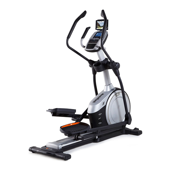
BEFORE YOU BEGIN Thank you for selecting the revolutionary reading this manual, please see the front cover of this NORDICTRACK C 7.5 elliptical. The C 7.5 elliptical manual. To help us assist you, note the product model ® provides an impressive selection of features designed number and serial number before contacting us. -
Page 6: Part Identification Chart
PART IDENTIFICATION CHART Use the drawings below to identify the small parts needed for assembly. The number in parentheses below each drawing is the key number of the part, from the PART LIST near the end of this manual. The number following the key number is the quantity needed for assembly. -
Page 7: Assembly
ASSEMBLY • Assembly requires two persons. • In addition to the included tool(s), assembly requires the following tools: • Place all parts in a cleared area and remove the one Phillips screwdriver packing materials. Do not dispose of the packing materials until you finish all assembly steps. - Page 8 3. Press the Cover Mounts (106) on the underside of the Rear Stabilizer Cover (15) into the Rear Stabilizer (2). 4. With the help of a second person, place some of the packing materials (not shown) under the front of the Frame (1). Have the second per- son hold the Frame to prevent it from tipping while you complete this step.
- Page 9 5. Orient the Upright (4) as shown. Have a second person hold the Upright near the Frame (1). See the inset drawing. Locate the wire tie (A) in the lower end of the Upright (4). Tie the wire tie to the Main Wire (110). Then, pull the upper end of the wire tie until the Main Wire is routed through the Upright.
- Page 10 7. Using a plastic bag to keep your fingers clean, apply some of the included grease to the Pivot Axle (35) and to two 16mm Wave Washers (54). Insert the Pivot Axle (35) through the Upright (4) and center it. Tip: It may be helpful to use a rubber mallet.
- Page 11 9. Untie and discard the wire tie on the Main Wire (110). While a second person holds the Console (7) near the Upright (4), connect the wires on the Console to the Main Wire (110) and to the Sensor Wires (63). Insert the excess wire into the Upright (4).
- Page 12 11. Orient the Right Pedal Arm (58) as shown. Apply grease to the axle on the Right Pedal Arm (58). Attach the Right Pedal Arm (58) to the Right Roller Arm (59) with an M8 x 14mm Shoulder Screw (79), a Small Axle Cover (55), and an M8 Washer (97).
- Page 13 13. Orient the Rear Upright Cover (81) as shown. Attach the Rear Upright Cover (81) to the Upright (4) with four M4 x 16mm Screws (101); start all the Screws, and then tighten them. Next, orient the Front Upright Cover (117) as shown.
- Page 14 15. Identify the Right Leg Inner Cover (83) and orient it as shown. Attach the Right Leg Inner Cover (83) to the Right Upper Body Leg (60) with an M4 x 16mm Screw (101) and an M5 Washer (94). Next, identify the Right Leg Outer Cover (69) and orient it as shown.
- Page 15 17. Attach the Tablet Holder (9) to the Console (7) with four #8 x 12mm Screws (111); start all the Screws, and then tighten them. 18. Make sure that all parts are properly tightened before you use the elliptical. Extra parts may be included. Place a mat beneath the elliptical to protect the floor.
-
Page 16: How To Use The Elliptical
HOW TO USE THE ELLIPTICAL HOW TO PLUG IN THE POWER CORD Follow the steps below to plug in the power cord. This product must be earthed. If it should 1. Plug the indicated end of the power cord into the malfunction or break down, earthing provides a path of socket on the frame. - Page 17 HOW TO MOVE THE ELLIPTICAL HOW TO LEVEL THE ELLIPTICAL Due to the size and weight of the elliptical, moving If the elliptical it requires two persons. Stand in front of the elliptical, rocks slightly on hold the upright, and place one foot against one of the your floor during wheels.
- Page 18 HOW TO EXERCISE ON THE ELLIPTICAL To mount the elliptical, hold the handlebars or the Upper upper body arms and step onto the pedal that is in the Body Arms lower position. Then, step onto the other pedal. Push the pedals until they begin to move with a continuous motion.
- Page 19 CONSOLE DIAGRAM FEATURES OF THE CONSOLE You can also listen to your favorite workout music or audio books with the console sound system while you The advanced console offers an array of features exercise. designed to make your workouts more effective and To turn on the power, see page 20.
- Page 20 HOW TO TURN ON THE POWER HOW TO USE THE MANUAL MODE IMPORTANT: If the elliptical has been exposed to 1. Begin pedaling or press any button on the cold temperatures, allow it to warm to room tem- console to turn on the console. perature before you turn on the power.
- Page 21 4. Follow your progress with the display. Speed—This display mode will show your pedaling speed in miles per hour or kilometers per hour. The display can show the following workout Time—When the manual mode is selected, this information: display mode will show the elapsed time. When a workout is selected, this display mode will show either the time remaining in the workout or the elapsed time.
- Page 22 Press the Home button repeatedly to pause the If the display does not show your heart rate, make workout, view your workout results, and exit the sure that your hands are positioned as described. workout and return to the manual mode. Be careful not to move your hands excessively or to squeeze the contacts tightly.
- Page 23 HOW TO USE AN ONBOARD WORKOUT show your progress. The flashing segment of the profile represents the current segment of the work- 1. Begin pedaling or press any button on the out. The height of the flashing segment indicates console to turn on the console. the target speed or the resistance level for the cur- rent segment.
- Page 24 The workout will continue in this way until the last Next, press the play button on segment ends. your personal audio player. Adjust the volume level To pause the console, press the Home button or using the volume increase simply stop pedaling. When the console is paused, and decrease buttons on the the time will flash in the display.
- Page 25 HOW TO CONNECT YOUR SMART DEVICE TO THE 4. Disconnect your smart device from the console CONSOLE if desired. The console supports BLUETOOTH connections to To disconnect your smart device from the console, smart devices via the iFit app and to compatible heart press and hold the Bluetooth Smart button on the rate monitors.
- Page 26 HOW TO CHANGE CONSOLE SETTINGS Incline System Calibration—If the incline sys- tem is not functioning properly, it may need to be 1. Select the settings mode. calibrated. To calibrate the incline system, press the Ramp increase or decrease button. The ramp To select the settings mode, press the Settings will move upward and downward as it calibrates.
-
Page 27: Maintenance And Troubleshooting
MAINTENANCE AND TROUBLESHOOTING MAINTENANCE Note: For clarity, the left shield and the left disc ring are shown removed in the drawing below. Regular maintenance is important for optimal performance and to reduce wear. Inspect and properly Locate the Reed Switch (38). Turn the Pulley (19) until tighten all parts each time the elliptical is used. - Page 28 HOW TO ADJUST THE REED SWITCH Locate the Reed Switch (38). Turn the Pulley (19) until a Magnet (43) is aligned with the Reed Switch. If the console does not display correct feedback, the reed switch should be adjusted. To adjust the reed switch, first unplug the power cord.
- Page 29 HOW TO ADJUST THE DRIVE BELT See EXPLODED DRAWING C on page 35. Identify the Left and Right Shields (73, 74). Remove If the pedals slip while you are pedaling, even while the M4 x 19mm Screws (5), the M4 x 25mm Screws the resistance is adjusted to the highest level, the drive (126), and the M4 x 48mm Screw (107) from the Left and Right Shields;...
-
Page 30: Exercise Guidelines
EXERCISE GUIDELINES Burning Fat—To burn fat effectively, you must exer- WARNING: cise at a low intensity level for a sustained period of Before beginning this time. During the first few minutes of exercise, your or any exercise program, consult your physi- body uses carbohydrate calories for energy. -
Page 31: Part List
PART LIST Model No. NTEVEL89816.0 R0416A Key No. Qty. Description Key No. Qty. Description Frame Roller Rear Stabilizer Pedal Arm Cap Ramp Large Axle Cover Upright 16mm Wave Washer M4 x 19mm Screw Small Axle Cover Front Stabilizer Roller Arm Bushing... - Page 32 Key No. Qty. Description Key No. Qty. Description M4 x 16mm Screw Disc Ring M8 Locknut Front Upright Cover M6 x 12mm Screw Shield Cover Cap M10 x 122mm Screw Power Cord M10 Split Washer Ramp Axle Cover Mount Small Frame Bushing M4 x 48mm Screw Clevis Pin M6 x 13mm Screw...
-
Page 33: Exploded Drawing
EXPLODED DRAWING A Model No. NTEVEL89816.0 R0416A... - Page 34 EXPLODED DRAWING B Model No. NTEVEL89816.0 R0416A...
- Page 35 EXPLODED DRAWING C Model No. NTEVEL89816.0 R0416A...
-
Page 36: Ordering Replacement Parts
ORDERING REPLACEMENT PARTS To order replacement parts, please see the front cover of this manual. To help us assist you, be prepared to provide the following information when contacting us: • the model number and serial number of the product (see the front cover of this manual) •...
Need help?
Do you have a question about the NTEVEL89816.0 and is the answer not in the manual?
Questions and answers