Advertisement
Table of Contents
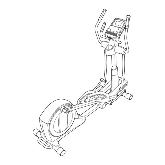
Model No. NTEVEL87910.1
Serial No.
Write the serial number in the space
above for reference.
Serial Number
Decal (under frame)
QUESTIONS?
If you have questions, or if there are
missing parts, please contact us:
UK
Call: 08457 089 009
From Ireland: 053 92 36102
Website: www.iconsupport.eu
E-mail: csuk@iconeurope.com
Write:
ICON Health & Fitness, Ltd.
c/o HI Group PLC
Express Way
Whitwood, West Yorkshire
WF10 5QJ
UK
AUSTRALIA
Call: 1-800-237-173
E-mail:
australiacc@iconfitness.com
CAUTION
Read all precautions and instruc-
tions in this manual before using
this equipment. Keep this manual
for future reference.
USERʼS MANUAL
www.iconeurope.com
Advertisement
Table of Contents

Related Manuals for NordicTrack NordicTrack E 7.0 NTEVEL87910


Summary of Contents for NordicTrack NordicTrack E 7.0 NTEVEL87910
- Page 1 USERʼS MANUAL Model No. NTEVEL87910.1 Serial No. Write the serial number in the space above for reference. Serial Number Decal (under frame) QUESTIONS? If you have questions, or if there are missing parts, please contact us: Call: 08457 089 009 From Ireland: 053 92 36102 Website: www.iconsupport.eu E-mail: csuk@iconeurope.com...
-
Page 2: Table Of Contents
TABLE OF CONTENTS WARNING DECAL PLACEMENT ............. .2 IMPORTANT PRECAUTIONS . -
Page 3: Important Precautions
IMPORTANT PRECAUTIONS WARNING: To reduce the risk of serious injury, read all important precautions and instructions in this manual and all warnings on your elliptical before using your elliptical. ICON assumes no responsibility for personal injury or property damage sustained by or through the use of this product. -
Page 4: Before You Begin
BEFORE YOU BEGIN Thank you for selecting the revolutionary NordicTrack manual. To help us assist you, note the product model ® E 7.0 elliptical. The E 7.0 elliptical provides an impres- number and serial number before contacting us. The sive selection of features designed to make your model number and the location of the serial number workouts at home more effective and enjoyable. -
Page 5: Assembly
ASSEMBLY Assembly requires two persons. Place all parts of the elliptical in a cleared area and remove the packing materials. Do not dispose of the packing materials until assembly is completed. In addition to the included tool(s), assembly requires a Phillips screwdriver and a rubber mallet See the drawings below to identify the small parts needed for assembly. - Page 6 To make assembly easier, read the information on page 5 before you begin. Orient the Rear Stabilizer (4) as shown. Handle Attach the Rear Stabilizer (4) to the Folding Frame (2) with two M10 x 95mm Patch Screws (100). Next, hold the handle on the Rear Stabilizer (4), press the Latch Button (67), and lower the Rear Stabilizer and the Folding Frame (2) to the floor.
- Page 7 3. Identify and orient the Upright (5) and the Top Cover (27) as shown. Slide the Top Cover (27) upward onto the Wire Tie Upright (5). Then, have a second person hold the Upright (5) and the Top Cover (27) near the Main Frame (1) until step 4.
- Page 8 5. Using a small plastic bag to keep your fingers clean, apply a coat of the included grease to the Upright Axle (48) and to two Wave Washers Avoid damaging the (118). Main Wire (60) Tip: Avoid damaging the Main Wire (60). Insert the Upright Axle (48) through the Upright (5) and center it.
- Page 9 7. Apply grease to the axle on the right Crank Arm (39). Orient a Pedal Arm Sleeve (46) so that the flat side is facing the elliptical. Slide the Pedal Arm Sleeve onto the axle on the right Crank Arm (39).
- Page 10 9. Orient the Ramp Cover (131) around the Upright (5) as shown. Press the tabs on the Ramp Cover (131) into the Ramp (130). 10. Apply grease to a Link Arm Axle (114). Insert the Link Arm Axle (114) into the Right Upper Body Leg (6) and the Right Link Arm (43) from the side shown.
- Page 11 11. Identify the Right Upper Body Arm (8), which is marked with a “Right” sticker, and orient it as shown. Have a second person hold the Right Upper Body Arm (8) near the Right Upper Body Leg (6). Attach the Right Upper Body Arm (8) to the Right Upper Body Leg (6) with three M8 x 16mm Patch Screws (102) and three M8 Split Washers (103).
- Page 12 13. Orient the Rear Upright Cover (25) as shown. Attach the Rear Upright Cover (25) to the Upright (5) with four M4 x 19mm Screws (123). 14. Untie and discard the wire tie attached to the Main Wire (60). Avoid pinching the wires While a second person holds the Console (33) near the Upright (5), connect the wires on the...
- Page 13 15. Orient the Front Upright Cover (24) as shown. Attach the Front Upright Cover (24) around the Upright (5) by pressing the tabs on the Front Upright Cover into the Rear Upright Cover (25). 16. Plug the Power Adapter (138) into the Power Receptacle (135).
-
Page 14: How To Use The Elliptical
HOW TO USE THE ELLIPTICAL HOW TO PLUG IN THE POWER ADAPTER HOW TO FOLD AND UNFOLD THE ELLIPTICAL IMPORTANT: If the elliptical has been exposed to When the elliptical cold temperatures, allow it to warm to room tem- is not in use, the Pedal Arm perature before plugging in the power adapter. - Page 15 HOW TO MOVE THE ELLIPTICAL HOW TO EXERCISE ON THE ELLIPTICAL To move the elliptical, first fold it as described above. To mount the elliptical, hold the upper body arms and Next, stand in front of the elliptical, hold the upright, step onto the pedal that is in the lowest position.
- Page 16 CONSOLE DIAGRAM FEATURES OF THE CONSOLE The advanced console offers an array of features designed to make your workouts more effective and enjoyable. When you use the manual mode of the console, you can change the resistance of the pedals with the touch of a button.
- Page 17 HOW TO ACTIVATE THE CONSOLE 3. Change the resistance of the pedals as desired. The included power adapter must be used to operate the elliptical. See HOW TO PLUG IN THE POWER As you pedal, change the resistance of the pedals ADAPTER on page 14.
- Page 18 5. Measure your heart rate if desired. HOW TO USE A PRESET WORKOUT 1. Begin pedaling or press any button on the You can measure you heart rate using either the console to turn on the console. handgrip pulse sensor or the optional chest pulse sensor (see page 21 for information about the optional chest pulse sensor).
- Page 19 The workout profile will If the resistance level for the current segment is show your progress. too high or too low, you can manually override the Current Segment The flashing segment of setting by pressing the Digital Resistance buttons. IMPORTANT: When the current segment of the the profile represents workout ends, the pedals will automatically the current segment of...
- Page 20 HOW TO USE THE IFIT TRAINING MODE HOW TO USE THE INFORMATION MODE The optional iFit Live module allows your console to The console features an information mode that allows communicate with your wireless network and unlocks you to view usage information, select a unit of mea- exciting new features.
- Page 21 4. Adjust the contrast level of the display if 7. Check the status of the iFit Live module if desired. desired. The currently selected contrast level will also To check the status of the iFit Live module, press appear in the display. To change the contrast level, the increase and decrease buttons until the bullet press the increase and decrease buttons until the appears next to the words CHECK WIFI STATUS...
-
Page 22: Maintenance And Troubleshooting
MAINTENANCE AND TROUBLESHOOTING Inspect and tighten all parts of the elliptical regularly. Next, look into the access opening and locate the Replace any worn parts immediately. Reed Switch (69). Rotate the Large Pulley (74) until a Pulley Magnet (75) is aligned with the Reed Switch. To clean the elliptical, use a damp cloth and a small amount of mild soap. - Page 23 HOW TO ADJUST THE DRIVE BELT Then, remove the M4 x 16mm Round Head Screws (134) and the M4 x 42mm Screws (120) from the If you can feel the pedals slip while you are pedaling, Right and Left Shields (18, 19). (Note: Not all Screws even when the resistance is adjusted to the highest are shown.
-
Page 24: Exercise Guidelines
EXERCISE GUIDELINES WARNING: Burning Fat—To burn fat effectively, you must exer- cise at a low intensity level for a sustained period of Before beginning this time. During the first few minutes of exercise, your or any exercise program, consult your physi- body uses carbohydrate calories for energy. - Page 25 SUGGESTED STRETCHES The correct form for several basic stretches is shown at the right. Move slowly as you stretch—never bounce. 1. Toe Touch Stretch Stand with your knees bent slightly and slowly bend forward from your hips. Allow your back and shoulders to relax as you reach down toward your toes as far as possible.
- Page 26 NOTES...
-
Page 27: Part List
PART LIST Model No. NTEVEL87910.1 R0111A Key No. Qty. Description Key No. Qty. Description Main Frame Large Latch Spring Folding Frame Latch Insert Front Stabilizer Long Latch Spring Rear Stabilizer Arm/Leg Bushing Upright M4 x 16mm Flat Head Screw Right Upper Body Leg Small Axle Cover Left Upper Body Leg Upright Bushing... - Page 28 Key No. Qty. Description Key No. Qty. Description Small Pedal Arm Snap Ring M4 x 19mm Screw M8 x 16mm Patch Screw Large Pedal Arm Snap Ring M8 Split Washer M4 x 8mm Screw Right Pedal Pad M10 Locknut Pulse Wire Long C-pin M4 x 16mm Screw Short C-pin...
-
Page 29: Exploded Drawing
EXPLODED DRAWING A Model No. NTEVEL87910.1 R0111A... - Page 30 EXPLODED DRAWING B Model No. NTEVEL87910.1 R0111A...
- Page 31 EXPLODED DRAWING C Model No. NTEVEL87910.1 R0111A...
-
Page 32: Ordering Replacement Parts
ORDERING REPLACEMENT PARTS To order replacement parts, see the front cover of this manual. To help us assist you, please be prepared to provide the following information when contacting us: • the model number and serial number of the product (see the front cover of this manual) •...
Need help?
Do you have a question about the NordicTrack E 7.0 NTEVEL87910 and is the answer not in the manual?
Questions and answers