Table of Contents
Advertisement
Quick Links
All manuals and user guides at all-guides.com
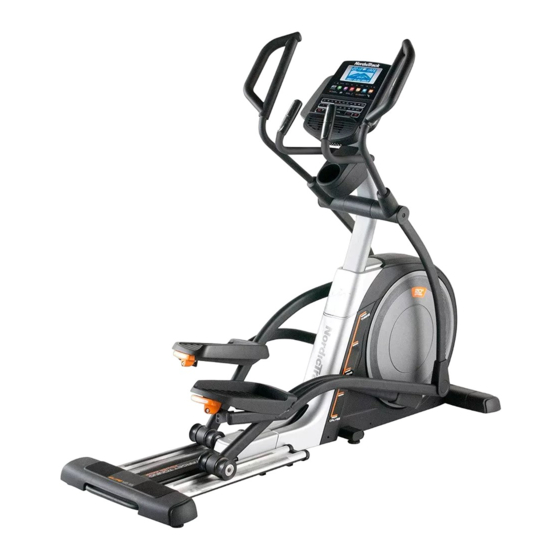
Model No. NTEVEL13014.0
Serial No.
USER'S MANUAL
Write the serial number in the space
above for reference.
Serial Number Decal
(under frame)
CUSTOMER SERVICE
UNITED KINGDOM
Call: 0330 123 1045
From Ireland: 053 92 36102
Website: www.iconsupport.eu
E-mail: csuk@iconeurope.com
Write:
ICON Health & Fitness, Ltd.
Unit 1D, The Gateway
Fryers Way, Silkwood Park
OSSETT
WF5 9TJ
UNITED KINGDOM
AUSTRALIA
Call: 1800 993 770
E-mail: australiacc@iconfitness.com
Write:
ICON Health & Fitness
PO Box 635
WINSTON HILLS NSW 2153
AUSTRALIA
CAUTION
Read all precautions and instruc-
tions in this manual before using
this equipment. Keep this manual
for future reference.
www.iconeurope.com
Advertisement
Table of Contents

Related Manuals for NordicTrack ELITE 12.5


Summary of Contents for NordicTrack ELITE 12.5
- Page 1 All manuals and user guides at all-guides.com Model No. NTEVEL13014.0 Serial No. USER’S MANUAL Write the serial number in the space above for reference. Serial Number Decal (under frame) CUSTOMER SERVICE UNITED KINGDOM Call: 0330 123 1045 From Ireland: 053 92 36102 Website: www.iconsupport.eu E-mail: csuk@iconeurope.com Write:...
-
Page 2: Table Of Contents
Apply the decal in the location shown. Note: The decal(s) may not be shown at actual size. NORDICTRACK is a registered trademark of ICON Health & Fitness, Inc. -
Page 3: Important Precautions
All manuals and user guides at all-guides.com IMPORTANT PRECAUTIONS WARNING: To reduce the risk of burns, fire, electric shock, or injury to persons, read all important precautions and instructions in this manual and all warnings on your elliptical before using your elliptical. ICON assumes no responsibility for personal injury or property damage sus- tained by or through the use of this product. -
Page 4: Before You Begin
Thank you for selecting the revolutionary reading this manual, please see the front cover of this NORDICTRACK ELITE 12.5 elliptical. The ELITE 12.5 manual. To help us assist you, note the product model ® elliptical provides an impressive selection of features number and serial number before contacting us. -
Page 5: Part Identification Chart
All manuals and user guides at all-guides.com PART IDENTIFICATION CHART Use the drawings below to identify the small parts needed for assembly. The number in parentheses below each drawing is the key number of the part, from the PART LIST near the end of this manual. The number following the key number is the quantity needed for assembly. -
Page 6: Assembly
All manuals and user guides at all-guides.com ASSEMBLY • Assembly requires two persons. • In addition to the included tool(s), assembly requires the following tools: • Place all parts in a cleared area and remove the one Phillips screwdriver packing materials. Do not dispose of the packing materials until you fi... - Page 7 All manuals and user guides at all-guides.com 3. Orient the Rear Stabilizer Cover (2) as shown, and press it onto the Frame (1). Attach the Rear Stabilizer Cover (2) with two M4 x 16mm Screws (104). 4. With the help of a second person, place some of the packing materials (not shown) under the front of the Frame (1).
- Page 8 All manuals and user guides at all-guides.com 5. Orient the Front Stabilizer Cover (8) as shown, and route the Power Cord (not shown) over the top of the Front Stabilizer Cover. Then, press the Front Stabilizer Cover onto the Frame (1). Attach the Front Stabilizer Cover (8) with two M4 x 16mm Screws (104).
- Page 9 All manuals and user guides at all-guides.com 7. Locate the Right Upper Saddle Bracket (121) on the Right Roller Arm (45). Next, locate the Lower Saddle Bracket (26) on the right side of the elliptical. Attach the Right Upper Saddle Bracket (121) to the Lower Saddle Bracket (26) with two M10 x 70mm Screws (139).
-
Page 10: The Chest Heart Rate Monitor
All manuals and user guides at all-guides.com THE CHEST HEART RATE MONITOR HOW TO PUT ON THE HEART RATE MONITOR • Do not expose the heart rate monitor to direct sun- light for extended periods of time; do not expose it to The heart rate temperatures above 122°... -
Page 11: How To Use The Elliptical
All manuals and user guides at all-guides.com HOW TO USE THE ELLIPTICAL HOW TO PLUG IN THE POWER CORD Follow the steps below to plug in the power cord. This product must be earthed. If it should malfunc- 1. Plug the indicated end of the power cord into the tion or break down, earthing provides a path of least socket on the frame. - Page 12 All manuals and user guides at all-guides.com HOW TO MOVE THE ELLIPTICAL HOW TO ADJUST THE POSITIONS OF THE PEDALS Due to the size and weight of the elliptical, moving it requires two persons. Stand in front of the ellipti- Each pedal can be adjusted to several positions.
- Page 13 All manuals and user guides at all-guides.com HOW TO EXERCISE ON THE ELLIPTICAL HOW TO LEVEL THE ELLIPTICAL To mount the elliptical, hold the upper body arms or If the elliptical rocks slightly on your floor during use, the handlebars and step onto the pedal that is in the turn one or both of the leveling feet beneath the rear lower position.
- Page 14 All manuals and user guides at all-guides.com CONSOLE DIAGRAM MAKE YOUR FITNESS GOALS A REALITY WITH Upload your workout results to the iFit cloud IFIT.COM and track your accomplishments. With your new iFit-compatible fitness equipment, you can use an array of features on iFit.com to make your Set calorie, time, or distance goals for your fitness goals a reality: workouts.
- Page 15 All manuals and user guides at all-guides.com FEATURES OF THE CONSOLE HOW TO TURN ON THE POWER IMPORTANT: If the elliptical has been exposed to The advanced console offers an array of features designed to make your workouts more effective and cold temperatures, allow it to warm to room tem- perature before you turn on the power.
- Page 16 All manuals and user guides at all-guides.com HOW TO USE THE MANUAL MODE Calories—This display mode will show the approx- imate number of calories you have burned. 1. Begin pedaling or press any button on the console to turn on the console. Calories per Hour (Calories/Hr)—This display mode will show the approximate number of calories See HOW TO TURN ON THE POWER on...
- Page 17 All manuals and user guides at all-guides.com As you exercise, the workout intensity level bar When your pulse is detected, a heart symbol will will indicate the approximate intensity level of your flash in the display each time your heart beats, exercise.
- Page 18 All manuals and user guides at all-guides.com HOW TO USE AN ONBOARD WORKOUT the profile will begin to flash. If a different resis- tance level, ramp incline level, and/or target rpm is 1. Begin pedaling or press any button on the programmed for the next segment, the resistance console to turn on the console.
- Page 19 All manuals and user guides at all-guides.com HOW TO USE A SET-A-GOAL WORKOUT Note: The calorie goal is an estimate of the number of calories that you will burn during 1. Begin pedaling or press any button on the the workout. The actual number of calories that console to turn on the console.
- Page 20 All manuals and user guides at all-guides.com HOW TO USE AN IFIT WORKOUT download, you must add them to your schedule on www.iFit.com. You must have an iFit module to use an iFit workout. To purchase an iFit module at any time, go to Press the Map button, the Train button, or the Lose www.iFit.com or call the telephone number on the Wt.
- Page 21 All manuals and user guides at all-guides.com 6. Follow your progress with the display. 7. Measure your heart rate if desired. See step 4 on page 16. See step 5 on page 17. 8. Turn on the fan if desired. The My Trail tab will show a map of the trail or it will show a track and the number of laps you complete.
- Page 22 All manuals and user guides at all-guides.com HOW TO CHANGE CONSOLE SETTINGS Units—The currently selected unit of measurement will appear in the display. To change the unit of 1. Select the settings mode. measurement, press the Enter button repeatedly. To view distance in miles, select ENGLISH. To view To select the settings mode, press the Settings distance in kilometers, select METRIC.
- Page 23 All manuals and user guides at all-guides.com HOW TO USE THE SOUND SYSTEM Next, press the play button on your personal audio player. Adjust the volume level using the volume To play music or audio books through the console increase and decrease buttons on the console or the sound system while you exercise, plug a 3.5 mm male volume control on your personal audio player.
-
Page 24: Maintenance And Troubleshooting
All manuals and user guides at all-guides.com MAINTENANCE AND TROUBLESHOOTING MAINTENANCE When the ramp stops moving, the ramp is calibrated. Then, press the Calorie Workouts button repeatedly to Inspect and tighten all parts of the elliptical regularly. exit the calibration mode. Replace any worn parts immediately. - Page 25 All manuals and user guides at all-guides.com HOW TO ADJUST THE DRIVE BELT Then, look between the Shields (73, 74) and locate the M8 Locknut (102). Tighten the Locknut until the Drive If the pedals slip while you are pedaling, even while Belt (113) is tight.
-
Page 26: Exercise Guidelines
All manuals and user guides at all-guides.com EXERCISE GUIDELINES Burning Fat—To burn fat effectively, you must exer- WARNING: cise at a low intensity level for a sustained period of Before beginning this time. During the first few minutes of exercise, your or any exercise program, consult your physi- body uses carbohydrate calories for energy. - Page 27 All manuals and user guides at all-guides.com SUGGESTED STRETCHES The correct form for several basic stretches is shown at the right. Move slowly as you stretch; never bounce. 1. Toe Touch Stretch Stand with your knees bent slightly and slowly bend forward from your hips.
-
Page 28: Part List
All manuals and user guides at all-guides.com PART LIST Model No. NTEVEL13014.0 R0714A Key No. Qty. Description Key No. Qty. Description Frame Large Roller Rear Stabilizer Cover Left Lower Grip Ramp Axle Cover Upright Left Roller Arm Cover Rear Stabilizer Disc Cover Right Front Stabilizer Shield Cover... - Page 29 All manuals and user guides at all-guides.com Key No. Qty. Description Key No. Qty. Description Idler Screw M10 x 20mm Screw M8 Locknut M6 Washer Pedal Pin M10 x 48mm Bolt M4 x 16mm Screw M10 x 36mm Bolt Lift Frame M10 Washer Small Roller M4 x 10mm Screw...
-
Page 30: Exploded Drawing
All manuals and user guides at all-guides.com EXPLODED DRAWING A Model No. NTEVEL13014.0 R0714A... - Page 31 All manuals and user guides at all-guides.com EXPLODED DRAWING B Model No. NTEVEL13014.0 R0714A 137 138...
-
Page 32: Ordering Replacement Parts
All manuals and user guides at all-guides.com ORDERING REPLACEMENT PARTS To order replacement parts, please see the front cover of this manual. To help us assist you, be prepared to provide the following information when contacting us: • the model number and serial number of the product (see the front cover of this manual) •...
Need help?
Do you have a question about the ELITE 12.5 and is the answer not in the manual?
Questions and answers