Table of Contents
Advertisement
Advertisement
Chapters
Table of Contents

Subscribe to Our Youtube Channel
Related Manuals for FLIR A310 ex


Summary of Contents for FLIR A310 ex
- Page 1 User’s manual FLIR A310 ex...
- Page 3 User’s manual FLIR A310 ex #T559891; r. AD/38469/38469; en-US...
-
Page 5: Table Of Contents
Customer help ..................4 General .................. 4 Submitting a question ..............4 Downloads ................5 Safety information ................6 What is FLIR A310 ex?................7 Typical system overview..............8 Typical system setup procedure............9 Technical data ................. 10 Online field-of-view calculator ............ 10 Note about technical data ............10 Note about authoritative versions.......... - Page 6 Table of contents History of infrared technology............43 Theory of thermography..............46 19.1 Introduction ................46 19.2 The electromagnetic spectrum........... 46 19.3 Blackbody radiation..............46 19.3.1 Planck’s law ..............47 19.3.2 Wien’s displacement law..........48 19.3.3 Stefan-Boltzmann's law ..........49 19.3.4 Non-blackbody emitters..........
-
Page 7: Disclaimers
FLIR Systems AB from Microsoft Licensing, GP or its manship and provided that it is returned to FLIR Systems within the said one- affiliates (“MS”). Those installed software products of MS origin, as well year period. - Page 8 Disclaimers html. The source code for the libraries Qt4 Core and Qt4 GUI may be re- quested from FLIR Systems AB. #T559891; r. AD/38469/38469; en-US...
-
Page 9: Notice To User
2.7 Important note about this manual FLIR Systems issues generic manuals that cover several cameras within a model line. This means that this manual may contain descriptions and explanations that do not apply to your particular camera model. -
Page 10: Customer Help
• The communication protocol, or method, between the camera and your device (for ex- ample, HDMI, Ethernet, USB, or FireWire) • Device type (PC/Mac/iPhone/iPad/Android device, etc.) • Version of any programs from FLIR Systems • Full name, publication number, and revision number of the manual #T559891; r. AD/38469/38469; en-US... -
Page 11: Downloads
Customer help 3.3 Downloads On the customer help site you can also download the following, when applicable for the product: • Firmware updates for your infrared camera. • Program updates for your PC/Mac software. • Freeware and evaluation versions of PC/Mac software. •... -
Page 12: Safety Information
Safety information CAUTION Do not point the infrared camera (with or without the lens cover) at strong energy sources, for example, devices that cause laser radiation, or the sun. This can have an unwanted effect on the accuracy of the camera. -
Page 13: What Is Flir A310 Ex
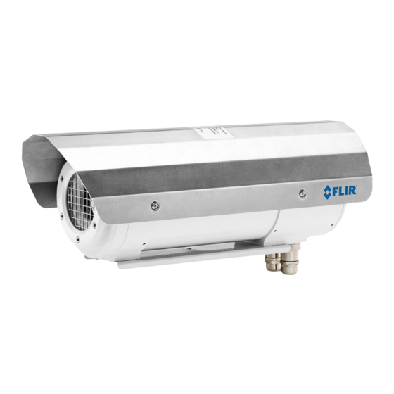
ATEX product directives and similar regulations. The FLIR A310 ex is an ATEX-proof solution, with a thermal imaging camera mounted in an enclosure, making it possible to monitor critical and other valuable assets in explosive atmospheres. -
Page 14: Typical System Overview
Typical system overview 1. Thermovision System Tools & Utilities CD-ROM. 2. Ethernet cable. 3. Optical-to-Ethernet converter. 4. FC connectors from the camera housing (including two spares). 5. 24 V DC power supply. 6. Pigtail cable from the housing. The color coding of the pigtail cable is: •... -
Page 15: Typical System Setup Procedure
• FLIR IR Monitor. • FLIR IR Camera Player. 6. Start FLIR IP Config to identify the unit in the network and automatically assign or manually set IP addresses, etc. For more information, see the FLIR IP Config manual on the User Documentation CD-ROM or on the Help menu in FLIR IP Config. -
Page 16: Technical Data
8.2 Note about technical data FLIR Systems reserves the right to change specifications at any time without prior notice. Please check http://support.flir.com for latest changes. -
Page 17: Flir A310 Ex 25
Rev.: 38447 Introduction The FLIR A310 ex is an ATEX-proof solution, with a thermal imaging camera mounted in an enclosure—making it possible to monitor critical and other valuable assets in explo- sive atmospheres. Process monitoring, quality control, and fire detection in potentially explosive locations are typical applications for the FLIR A310 ex. - Page 18 Technical data Explosion protection-specific data For use in EX zone 1, 2, 21, 22 Ignition protection category Flame-proof enclosure “d” Maximum surface temperature (according to tem- Maximum 85°C perature class T6) ATEX certification (version -AXC) • II 2G Ex db IIC T6 / T5 •...
- Page 19 Ethernet, type 100 Mbps Ethernet, standard IEEE 802.3 Ethernet, configuration Pigtail with FC-connector (fiber) Ethernet, communication TCP/IP socket-based FLIR proprietary Ethernet, video streaming MPEG-4, ISO/IEC 14496-1 MPEG-4 ASP@L5 Ethernet, image streaming 16-bit 320 × 240 pixels @ 7-8 Hz • Radiometric...
-
Page 20: Flir A310 Ex 45
Rev.: 38447 Introduction The FLIR A310 ex is an ATEX-proof solution, with a thermal imaging camera mounted in an enclosure—making it possible to monitor critical and other valuable assets in explo- sive atmospheres. Process monitoring, quality control, and fire detection in potentially explosive locations are typical applications for the FLIR A310 ex. - Page 21 Technical data Explosion protection-specific data For use in EX zone 1, 2, 21, 22. Ignition protection category Flame-proof enclosure “d” Maximum surface temperature (according to tem- Maximum 85°C perature class T6) ATEX certification (version -AXC) • II 2G Ex db IIC T6 / T5 •...
- Page 22 Ethernet, type 100 Mbps Ethernet, standard IEEE 802.3 Ethernet, configuration Pigtail with FC connector Ethernet, communication TCP/IP socket-based FLIR proprietary Ethernet, video streaming MPEG-4, ISO/IEC 14496-1 MPEG-4 ASP@L5 Ethernet, image streaming 16-bit 320 × 240 pixels @ 7-8 Hz • Radiometric...
-
Page 23: Mechanical Drawings
Mechanical drawings #T559891; r. AD/38469/38469; en-US... -
Page 25: Ec Type Examination Certificate
EC Type Examination Certificate #T559891; r. AD/38469/38469; en-US... -
Page 28: Ec Type Examination Certificate, 1St Supplement
EC Type Examination Certificate, 1st supplement #T559891; r. AD/38469/38469; en-US... -
Page 31: Ec Type Examination Certificate, 3Rd Supplement
EC Type Examination Certificate, 3rd supplement #T559891; r. AD/38469/38469; en-US... -
Page 34: Ec Declaration Of Conformity (Enclosure)
EC Declaration of conformity (enclosure) #T559891; r. AD/38469/38469; en-US... - Page 35 EG-Konformitätserklärung EC-Declaration of Conformity Déclaration de Conformité CE AT – Automation Technology GmbH • Hermann-Bössow-Strasse 6 – 8 • D-23843 Bad Oldesloe, Germany erklärt in alleiniger Verantwortung, declares in its sole responsibility, déclare sous sa seule responsabilité dass das Produkt IRCamSafeEX-AXB that the product IRCamSafeEX-AXC...
-
Page 36: Certiticate Of Conformity (Camera)
Certiticate of conformity (camera) #T559891; r. AD/38469/38469; en-US... -
Page 38: About Flir Systems
• Point Grey Research (2016) Figure 15.1 Patent documents from the early 1960s FLIR Systems has three manufacturing plants in the United States (Portland, OR, Bos- ton, MA, Santa Barbara, CA) and one in Sweden (Stockholm). Since 2007 there is also a manufacturing plant in Tallinn, Estonia. -
Page 39: More Than Just An Infrared Camera
15.1 More than just an infrared camera At FLIR Systems we recognize that our job is to go beyond just producing the best infra- red camera systems. We are committed to enabling all users of our infrared camera sys- tems to work more productively by providing them with the most powerful camera–... - Page 40 About FLIR Systems equipment and expertise to solve it within the shortest possible time. Therefore, there is no need to send your camera to the other side of the world or to talk to someone who does not speak your language.
-
Page 41: Glossary
Glossary absorption The amount of radiation absorbed by an object relative to the re- (absorption ceived radiation. A number between 0 and 1. factor) atmosphere The gases between the object being measured and the camera, nor- mally air. autoadjust A function making a camera perform an internal image correction. autopalette The IR image is shown with an uneven spread of colors, displaying cold objects as well as hot ones at the same time. - Page 42 Glossary image correc- A way of compensating for sensitivity differences in various parts of tion (internal or live images and also of stabilizing the camera. external) infrared Non-visible radiation, having a wavelength from about 2–13 μm. infrared isotherm A function highlighting those parts of an image that fall above, below or between one or more temperature intervals.
- Page 43 Glossary span The interval of the temperature scale, usually expressed as a signal value. spectral (radi- Amount of energy emitted from an object per unit of time, area and ant) emittance wavelength (W/m /μm) temperature A value which is the result of a subtraction between two temperature difference, or values.
-
Page 44: Thermographic Measurement Techniques
Thermographic measurement techniques 17.1 Introduction An infrared camera measures and images the emitted infrared radiation from an object. The fact that radiation is a function of object surface temperature makes it possible for the camera to calculate and display this temperature. However, the radiation measured by the camera does not only depend on the tempera- ture of the object but is also a function of the emissivity. - Page 45 Thermographic measurement techniques 17.2.1.1.1 Method 1: Direct method Follow this procedure: 1. Look for possible reflection sources, considering that the incident angle = reflection angle (a = b). Figure 17.1 1 = Reflection source 2. If the reflection source is a spot source, modify the source by obstructing it using a piece if cardboard.
- Page 46 Thermographic measurement techniques 3. Measure the radiation intensity (= apparent temperature) from the reflecting source using the following settings: • Emissivity: 1.0 • D You can measure the radiation intensity using one of the following two methods: Figure 17.3 1 = Reflection source Figure 17.4 1 = Reflection source Using a thermocouple to measure reflected apparent temperature is not recommended for two important reasons:...
-
Page 47: Reflected Apparent Temperature
Thermographic measurement techniques 5. Measure the apparent temperature of the aluminum foil and write it down. Figure 17.5 Measuring the apparent temperature of the aluminum foil. 17.2.1.2 Step 2: Determining the emissivity Follow this procedure: 1. Select a place to put the sample. 2. -
Page 48: Distance
50%. 17.6 Other parameters In addition, some cameras and analysis programs from FLIR Systems allow you to com- pensate for the following parameters: • Atmospheric temperature – i.e. the temperature of the atmosphere between the cam- era and the target •... -
Page 49: History Of Infrared Technology
History of infrared technology Before the year 1800, the existence of the infrared portion of the electromagnetic spec- trum wasn't even suspected. The original significance of the infrared spectrum, or simply ‘the infrared’ as it is often called, as a form of heat radiation is perhaps less obvious to- day than it was at the time of its discovery by Herschel in 1800. - Page 50 History of infrared technology When Herschel revealed his discovery, he referred to this new portion of the electromag- netic spectrum as the ‘thermometrical spectrum’. The radiation itself he sometimes re- ferred to as ‘dark heat’, or simply ‘the invisible rays’. Ironically, and contrary to popular opinion, it wasn't Herschel who originated the term ‘infrared’.
- Page 51 History of infrared technology Figure 18.4 Samuel P. Langley (1834–1906) The improvement of infrared-detector sensitivity progressed slowly. Another major break- through, made by Langley in 1880, was the invention of the bolometer. This consisted of a thin blackened strip of platinum connected in one arm of a Wheatstone bridge circuit upon which the infrared radiation was focused and to which a sensitive galvanometer re- sponded.
-
Page 52: Theory Of Thermography
Theory of thermography 19.1 Introduction The subjects of infrared radiation and the related technique of thermography are still new to many who will use an infrared camera. In this section the theory behind thermography will be given. 19.2 The electromagnetic spectrum The electromagnetic spectrum is divided arbitrarily into a number of wavelength regions, called bands, distinguished by the methods used to produce and detect the radiation. -
Page 53: Planck's Law
Such cavity radiators are commonly used as sources of radiation in tempera- ture reference standards in the laboratory for calibrating thermographic instruments, such as a FLIR Systems camera for example. If the temperature of blackbody radiation increases to more than 525°C (977°F), the source begins to be visible so that it appears to the eye no longer black. -
Page 54: Wien's Displacement Law
Theory of thermography where: Blackbody spectral radiant emittance at wavelength λ. λb Velocity of light = 3 × 10 Planck’s constant = 6.6 × 10 Joule sec. Boltzmann’s constant = 1.4 × 10 Joule/K. Absolute temperature (K) of a blackbody. λ... -
Page 55: Stefan-Boltzmann's Law
Theory of thermography Figure 19.5 Wilhelm Wien (1864–1928) The sun (approx. 6 000 K) emits yellow light, peaking at about 0.5 μm in the middle of the visible light spectrum. At room temperature (300 K) the peak of radiant emittance lies at 9.7 μm, in the far infra- red, while at the temperature of liquid nitrogen (77 K) the maximum of the almost insignif- icant amount of radiant emittance occurs at 38 μm, in the extreme infrared wavelengths. -
Page 56: Non-Blackbody Emitters
Theory of thermography Figure 19.7 Josef Stefan (1835–1893), and Ludwig Boltzmann (1844–1906) Using the Stefan-Boltzmann formula to calculate the power radiated by the human body, at a temperature of 300 K and an external surface area of approx. 2 m , we obtain 1 kW. - Page 57 Theory of thermography • A selective radiator, for which ε varies with wavelength According to Kirchhoff’s law, for any material the spectral emissivity and spectral absorp- tance of a body are equal at any specified temperature and wavelength. That is: From this we obtain, for an opaque material (since α...
-
Page 58: Infrared Semi-Transparent Materials
Theory of thermography 19.4 Infrared semi-transparent materials Consider now a non-metallic, semi-transparent body – let us say, in the form of a thick flat plate of plastic material. When the plate is heated, radiation generated within its volume must work its way toward the surfaces through the material in which it is partially ab- sorbed. -
Page 59: The Measurement Formula
The measurement formula As already mentioned, when viewing an object, the camera receives radiation not only from the object itself. It also collects radiation from the surroundings reflected via the ob- ject surface. Both these radiation contributions become attenuated to some extent by the atmosphere in the measurement path. - Page 60 U according to the same equation, and get (Equation 3): Solve Equation 3 for U (Equation 4): This is the general measurement formula used in all the FLIR Systems thermographic equipment. The voltages of the formula are: Table 20.1 Voltages Calculated camera output voltage for a blackbody of temperature i.e.
- Page 61 5 volts, the resulting curve would have been very much the same as our real curve extrapolated beyond 4.1 volts, provided the calibration algo- rithm is based on radiation physics, like the FLIR Systems algorithm. Of course there must be a limit to such extrapolations.
- Page 62 The measurement formula Figure 20.3 Relative magnitudes of radiation sources under varying measurement conditions (LW cam- era). 1: Object temperature; 2: Emittance; Obj: Object radiation; Refl: Reflected radiation; Atm: atmos- phere radiation. Fixed parameters: τ = 0.88; T = 20°C (+68°F); T = 20°C (+68°F).
-
Page 63: Emissivity Tables
Emissivity tables This section presents a compilation of emissivity data from the infrared literature and measurements made by FLIR Systems. 21.1 References 1. Mikaél A. Bramson: Infrared Radiation, A Handbook for Applications, Plenum press, N.Y. 2. William L. Wolfe, George J. Zissis: The Infrared Handbook, Office of Naval Research, Department of Navy, Washington, D.C. - Page 64 Emissivity tables Table 21.1 T: Total spectrum; SW: 2–5 µm; LW: 8–14 µm, LLW: 6.5–20 µm; 1: Material; 2: Specification; 3:Temperature in °C; 4: Spectrum; 5: Emissivity: 6:Reference (continued) Aluminum anodized, light 0.97 gray, dull Aluminum as received, plate 0.09 Aluminum as received, 0.09...
- Page 65 Emissivity tables Table 21.1 T: Total spectrum; SW: 2–5 µm; LW: 8–14 µm, LLW: 6.5–20 µm; 1: Material; 2: Specification; 3:Temperature in °C; 4: Spectrum; 5: Emissivity: 6:Reference (continued) Brass polished 0.03 Brass polished, highly 0.03 0.20 Brass rubbed with 80- grit emery Brass sheet, rolled...
- Page 66 Emissivity tables Table 21.1 T: Total spectrum; SW: 2–5 µm; LW: 8–14 µm, LLW: 6.5–20 µm; 1: Material; 2: Specification; 3:Temperature in °C; 4: Spectrum; 5: Emissivity: 6:Reference (continued) Chipboard untreated 0.90 polished 0.10 Chromium Chromium polished 500–1000 0.28–0.38 Clay fired 0.91 Cloth...
- Page 67 Emissivity tables Table 21.1 T: Total spectrum; SW: 2–5 µm; LW: 8–14 µm, LLW: 6.5–20 µm; 1: Material; 2: Specification; 3:Temperature in °C; 4: Spectrum; 5: Emissivity: 6:Reference (continued) Gold polished, carefully 200–600 0.02–0.03 polished, highly 0.02 Gold Granite polished 0.849 Granite rough...
- Page 68 Emissivity tables Table 21.1 T: Total spectrum; SW: 2–5 µm; LW: 8–14 µm, LLW: 6.5–20 µm; 1: Material; 2: Specification; 3:Temperature in °C; 4: Spectrum; 5: Emissivity: 6:Reference (continued) Iron and steel shiny, etched 0.16 Iron and steel wrought, carefully 40–250 0.28 polished...
- Page 69 Emissivity tables Table 21.1 T: Total spectrum; SW: 2–5 µm; LW: 8–14 µm, LLW: 6.5–20 µm; 1: Material; 2: Specification; 3:Temperature in °C; 4: Spectrum; 5: Emissivity: 6:Reference (continued) Lead unoxidized, 0.05 polished Lead red 0.93 Lead red, powder 0.93 Leather tanned 0.75–0.80...
- Page 70 Emissivity tables Table 21.1 T: Total spectrum; SW: 2–5 µm; LW: 8–14 µm, LLW: 6.5–20 µm; 1: Material; 2: Specification; 3:Temperature in °C; 4: Spectrum; 5: Emissivity: 6:Reference (continued) Nickel wire 200–1000 0.1–0.2 Nickel oxide 1000–1250 0.75–0.86 Nickel oxide 500–650 0.52–0.59 0.27 Oil, lubricating...
- Page 71 Emissivity tables Table 21.1 T: Total spectrum; SW: 2–5 µm; LW: 8–14 µm, LLW: 6.5–20 µm; 1: Material; 2: Specification; 3:Temperature in °C; 4: Spectrum; 5: Emissivity: 6:Reference (continued) Paper yellow 0.72 Plaster 0.86 Plaster plasterboard, 0.90 untreated Plaster rough coat 0.91 Plastic glass fibre lami-...
- Page 72 Emissivity tables Table 21.1 T: Total spectrum; SW: 2–5 µm; LW: 8–14 µm, LLW: 6.5–20 µm; 1: Material; 2: Specification; 3:Temperature in °C; 4: Spectrum; 5: Emissivity: 6:Reference (continued) Soil 0.92 0.95 Soil saturated with water alloy, 8% Ni, 18% 0.35 Stainless steel rolled...
- Page 73 Emissivity tables Table 21.1 T: Total spectrum; SW: 2–5 µm; LW: 8–14 µm, LLW: 6.5–20 µm; 1: Material; 2: Specification; 3:Temperature in °C; 4: Spectrum; 5: Emissivity: 6:Reference (continued) Water ice, smooth 0.97 Water ice, smooth –10 0.96 Water layer >0.1 mm 0–100 0.95–0.98 thick...
-
Page 74: Aoem Manual (German)
OEM manual (German) This section contains the original manual from the manufacturer of the enclosure. #T559891; r. AD/38469/38469; en-US... - Page 75 Betriebsanleitung IRCamSafeEX-AXC Ex-d Gehäuse für Infrarotkameras AT – Automation Technology GmbH Datum: 01.04.2016 Revision: 1.3 © AT – Automation Technology GmbH 2016...
- Page 76 1 Inhaltsverzeichnis Allgemeine Angaben........................2 Hersteller ..........................2 Einleitung ..........................2 Kennzeichnung ........................3 Allgemeine Sicherheitshinweise ...................... 4 Verwendung und Vorgesehener Einsatzbereich ................5 Zulässige Einbauten ......................... 5 Zulässige Kabeleinführungen und Steckverbinder ..............6 Ausführung mit vorkonfektionierten Anschlusskabeln ............6 Normenkonformität ........................
- Page 77 Bei den Kameragehäusen der Serie IRCamSafeEX-AXB/C handelt es sich um Schutzgehäuse für Infrarotkameras. Die Gehäuse sind für den Einsatz von Infrarotkameras der Serie FLIR A3XX/SC3XX und A615/SC6XX, sowie Flir G300A und AT IRS und Xenics Serval in explosionsgefährdeten Bereichen konzipiert. Die Variante–AXC ist zudem für den Einsatz in staubexplosionsgefährlicher Atmosphäre zugelassen.
- Page 78 2.3 Kennzeichnung Gehäusevariante 24V DC: AT – Automation Technology GmbH Hermann-Bössow-Straße 6 – 8 • 23843 Bad Oldesloe • Germany Phone: +49 4531 88011-0 • www.AutomationTechnology.de Model: IRCamSafeEX-AXC Serial No.: 71000260 Year: 2016 Power: 24VDC, 60W amb -40°C - +40°C / 60°C max.
-
Page 79: Allgemeine Sicherheitshinweise
3 Allgemeine Sicherheitshinweise Die Betriebsanleitung enthält grundlegende Sicherheitshinweise, die bei Aufstellung, Betrieb und Wartung zu beachten sind. Nichtbeachtung hat eine Gefährdung für Personen, Anlage und Umwelt zur Folge. Gefahr durch unbefugte Arbeiten am Gerät! Montage, Installation, Inbetriebnahme, Betrieb und Wartung dürfen ausschließlich von dazu befugtem und entsprechend geschultem Personal durchgeführt werden. - Page 80 4.1 Zulässige Einbauten Folgende Kamera und Optikkombinationen können eingesetzt werden. Kamera Optik Variante - AXC Flir A3XX, ohne Zusatzoptik SC3XX, 45° Zusatzoptik, f‘ = 10mm A3XXsc 15° Zusatzoptik, f‘ = 30mm 6° Zusatzoptik, f‘ = 76mm 90° Zusatzoptik, f‘ = 4mm Flir A615, 15°...
- Page 81 4.2 Zulässige Kabeleinführungen und Steckverbinder Für den Anschluss der Stromversorgungsleitung und der Datenübertragungsleitung stehen zwei druckfeste und zünddurchschlagsichere Kabeleinführungen zur Verfügung. Alternativ können druckfeste und zünddurchschlagsichere Steckverbindersysteme eingesetzt werden. Die Kabeleinführungen und Steckverbinderbuchsen sind vom Hersteller vormontiert. Optional wird vom Hersteller das Gehäuse zusätzlich mit bereits angeschlossenen Anschlusskabeln geliefert. Folgende EX-Kabeleinführungen sind für die Verwendung mit dem Schutzgehäuse geeignet.
- Page 82 • Zweite Anschlussseite ist nicht-konfektioniert und zum Spleißen geeignet • Typische Länge 5m Anschluss 2 (Stromversorgung) ist mit einem 3 adrigen Kupfer-Kabel (z.B. Helukabel 37264) mit folgenden Eigenschaften ausgestattet. • Manteldurchmesser: 9.8mm • Aderquerschnitt: 3 x 1,5mm feindrähtig • Typische Länge 5m, optional mit Stecker Stahl 8570/12-306 konfektioniert Kundenspezifische Längen und Konfektionierungen der freien Enden sind auf Anfrage möglich.
-
Page 83: Technische Daten
6 Technische Daten Allgemeine technische Daten: • Normal-Betriebsumgebungstemperaturbereich T : -40°C … +60°C • Schutzart: IP67 • Gewicht: 6,7 kg (ohne Kamera und Optik) • Leervolumen: 5,06l • Außenmaße (ohne Sonnendach und Anschlüsse): D=170mm, L=408mm • Gehäusematerial: Aluminium • Oberfläche: pulverbeschichtet, •... - Page 84 Abb. 1: Übersicht IRCamSafeEX-AXC (alle Maße in mm) – Änderungen vorbehalten Betriebsanleitung IRCamSafeEX-AXC Ex-d Gehäuse für Infrarotkameras 9 AT-Automation Technology GmbH...
- Page 85 7 Transport, Lagerung und Entsorgung Transport: Erschütterungsfrei in der Originalverpackung, nicht stürzen, vorsichtig handhaben. Lagerung: Trocken in der Originalverpackung lagern Entsorgung: Die umweltgerechte Entsorgung aller Bauteile gemäß den gesetzlichen Bestimmungen ist sicherzustellen. 8 Montage und Demontage Vor der Montage den Umgebungstemperaturbereich und die Schutzart gemäß Typenschild auf Zulässigkeit im Montagebereich prüfen.
- Page 86 9 Installation Installationsarbeiten nur durch Fachpersonal! Installationsarbeiten dürfen nur von dazu befugtem und entsprechend geschultem Personal durchgeführt werden. Geltende nationale Bestimmungen im Einsatzland, z.B. EN 60079-14 beachten. Die Montage der Kabeleinführungen oder gehäuseseitigen Steckverbinder und die Installation der Anschlussleitungen erfolgt durch den Hersteller oder durch vom Hersteller autorisiertes Personal.
- Page 87 9.1 Installation der Anschlussleitungen Leitungen Die Qualität der verwendeten Zuleitung ist so zu wählen, dass sie den thermischen und mechanischen Anforderungen im Einsatzbereich genügt. Die Kabel müssen den entsprechenden Richtlinien für direkte Einführung in druckfeste Kapselung nach EN 60079-14 genügen. Die Kabeleinführung ist mit Vergussmasse zur Abdichtung der Einzeladern auszuführen.
- Page 88 Nicht korrekt durchgeführte Installation! • Bitte beachten Sie die Gewindegrößen für die Leitungseinführungen in der Dokumentation des Betriebsmittels. • Die Anschlussleistung muss den geltenden Vorschriften entsprechen und über den erforderlichen Querschnitt verfügen. Der Durchmesser muss mit den Angaben auf der Kabeldurchführung übereinstimmen.
- Page 89 2. Konfigurieren der Ethernet-Verbindung zum Schutzgehäusekontroller mit dem Tool „EDS Configurator“ 3. Starten der Website des Schutzgehäusekontrollers und ggf. Konfigurieren der Netzwerk- Switch Einstellungen. 4. Prüfen und Konfigurieren der Ethernet-Verbindung zur Infrarotkamera mit dem Tool „FLIR IP Config“ 5. Starten der Monitorsoftware 6. Prüfen des Kamerabildes 7.
- Page 90 11 Wartung Der Betreiber einer elektrischen Anlage in explosionsgefährdeter Umgebung hat diese in ordnungsgemäßem Zustand zu halten, ordnungsgemäß zu betreiben, zu überwachen und Instandhaltungs- sowie Instandsetzungsarbeiten durchzuführen! Wartungsarbeiten und Arbeiten zur Störungsbeseitigung dürfen nur von Fachpersonal durchgeführt werden. Im Rahmen der Wartung sind vor allem die Teile, von denen die Zündschutzart und die Funktionsfähigkeit abhängen, auf Ihren ordnungsgemäßen Zustand zu prüfen.
- Page 91 11.2 Reinigung Die Reinigung des Gehäuses kann mit einem Tuch, Besen, Staubsauger o.ä. erfolgen. Sollte für die Reinigung des Sichtfensters die Demontage des Schutzgitters erforderlich sein ist das Gerät vorher spannungsfrei zu schalten. Das Fenster kann mit Wasser oder auch mit Isopropanol (vorausgesetzt das dieses in dem Bereich zulässig ist) gereinigt werden.
- Page 92 13 EG-Baumusterprüfbescheinigung Betriebsanleitung IRCamSafeEX-AXC Ex-d Gehäuse für Infrarotkameras 17 AT-Automation Technology GmbH...
- Page 93 Betriebsanleitung IRCamSafeEX-AXC Ex-d Gehäuse für Infrarotkameras 18 AT-Automation Technology GmbH...
- Page 94 Betriebsanleitung IRCamSafeEX-AXC Ex-d Gehäuse für Infrarotkameras 19 AT-Automation Technology GmbH...
- Page 95 Betriebsanleitung IRCamSafeEX-AXC Ex-d Gehäuse für Infrarotkameras 20 AT-Automation Technology GmbH...
- Page 96 14 EG-Konformitätserklärung EG-Konformitätserklärung EC-Declaration of Conformity Déclaration de Conformité CE AT – Automation Technology GmbH • Hermann-Bössow-Strasse 6 – 8 • D-23843 Bad Oldesloe, Germany erklärt in alleiniger Verantwortung, declares in its sole responsibility, déclare sous sa seule responsabilité dass das Produkt that the product IRCamSafeEX-AXC que le produit...
- Page 97 Betriebsanleitung IRCamSafeEX-AXC Ex-d Gehäuse für Infrarotkameras 22 AT-Automation Technology GmbH...
-
Page 98: Boem Manual (English)
OEM manual (English) This section contains a translation of the original manual from the manufacturer of the enclosure. The translation has been approved by the manufacturer. #T559891; r. AD/38469/38469; en-US... -
Page 99: Operating Instructions
Operating Instructions IRCamSafeEX-AXC Ex-d Enclosure for Infrared Cameras AT – Automation Technology GmbH Date: 4/1/2016 Version: 1.3 © AT – Automation Technology GmbH 2016... - Page 100 1 Contents General Information ........................2 Manufacturer .......................... 2 Introduction ..........................2 Labeling ........................... 3 General Safety Instructions ......................4 Use and Intended Area of Application .................... 5 Permitted Attachments ......................5 Permitted Cable Glands and Connectors ................6 Construction With Preassembled Connection Cables ............. 6 Compliance With Applicable Standards ..................
-
Page 101: General Information
FLIR A3XX/SC3XX and A615/SC6XX series, as well as the Flir G300A, AT IRS and Xenics Serval, in potentially explosive atmospheres. The AXC variant is also approved for use in explosive atmospheres caused by combustible dusts. -
Page 102: Labeling
2.3 Labeling 24-VDC enclosure variant: AT – Automation Technology GmbH Hermann-Bössow-Strasse 6–8 • 23843 Bad Oldesloe • Germany Phone: +49 4531 88011-0 • www.AutomationTechnology.de Model: IRCamSafeEX-AXC Serial No.: 71000260 Year: 2016 Power: 24 VDC, 60 W amb -40°C–+40°C/60°C max. Certificate: ZELM 12 ATEX 0485 X 0820 II 2G Ex db IIC T6 / T5... -
Page 103: General Safety Instructions
3 General Safety Instructions The operating instructions contain important safety instructions that must be observed when carrying out assembly, operation and maintenance work. Failure to observe the safety instructions may endanger people, the plant and the environment. Hazard caused by unauthorized work on the device Assembly, installation, commissioning, operation and maintenance work may only be performed by personnel who are authorized and trained to do so. -
Page 104: Use And Intended Area Of Application
4.1 Permitted Attachments The following camera and lens combinations can be used. Camera Lens model Flir A3XX, Without ancillary lens SC3XX, 45° ancillary lens, focal length = 10 mm A3XXsc 15° ancillary lens, focal length = 30mm 6° ancillary lens, focal length = 76mm 90°... -
Page 105: Permitted Cable Glands And Connectors
4.2 Permitted Cable Glands and Connectors There are two pressure-resistant, flameproof cable glands to connect the power supply line and the data transmission line. Alternatively, pressure-resistant, flameproof connector systems can be used. The cable glands and connectors are preassembled by the manufacturer. The enclosure can also be supplied by the manufacturer with the connection cables already connected. - Page 106 • Second terminal side is not assembled and can be spliced • Typical length: 5 m Connection 2 (electrical power supply) is equipped with a three-core copper cable (e.g. Helukabel 37264) that has the following properties: • Sheath diameter: 9.8 mm •...
-
Page 107: Compliance With Applicable Standards
5 Compliance With Applicable Standards The protective enclosures comply with the following standards and guidelines: • Directive 94/9/EC • EN 60079-0:2014; "Explosive atmospheres — Part 0: Equipment — General requirements" • EN 60079-1:2014; "Explosive atmospheres — Part 1: Equipment protection by flameproof enclosures 'd'"... -
Page 108: Technical Data
6 Technical Data General technical data: • Normal operating conditions temperature range T : -40°C to +60°C • Protection class: IP67 • Weight: 6.7 kg (without camera and lens) • Total capacity: 5.06l • External dimensions (excluding canopy and connections): diameter=170 mm; length=408 mm •... - Page 109 Fig. 1: Overview of IRCamSafeEX-AXC (all measurements in mm) — subject to change without notice Operating Instructions IRCamSafeEX-AXC Ex d Enclosure for Infrared Cameras 10 AT-Automation Technology GmbH...
-
Page 110: Transport, Storage And Disposal
7 Transport, Storage and Disposal Transport: The device should transported in its original packaging and should not be able to move around within the packaging. Handle the device with care; do not drop it. Storage: Store the device in its original packaging in a dry place. Disposal: All components must be disposed of in a manner that does not harm the environment and in line with legal requirements. -
Page 111: Installation
9 Installation Installation work must only be carried out by specialist personnel Installation work may only be performed by personnel who have been authorized and trained to do so. All applicable national regulations in the country in which the product is used must be observed (e.g. -
Page 112: Installing The Connection Lines
9.1 Installing the Connection Lines Lines The quality of the supply pipe used must meet the thermal and mechanical requirements in the area of application. The cables must comply with the applicable guidelines for direct entry into flameproof enclosures in line with EN 60079-14. Cable glands must be sealed with a sealing compound to waterproof the individual wires. -
Page 113: Locking The Rear Enclosure Cover
Incorrect Installation • Please observe the thread sizes for the cable glands in the operating instructions • The connection line must meet the applicable requirements and the cross section dimensions must be sufficient. The diameter must comply with the cable gland requirements •... -
Page 114: Commissioning
Configurator" tool 3. Load the website for the protective enclosure controller and if necessary, configure the network switch settings 4. Check and configure the Ethernet connection to the infrared camera using the "FLIR IP Config" tool 5. Start the monitor software 6. -
Page 115: Maintenance
11 Maintenance Operators of electrical systems in potentially explosive atmospheres must ensure that the system is kept in proper working order and is operated correctly. The operator must also monitor the system and carry out maintenance and repair work as required. Maintenance work and troubleshooting must only be performed by specialist personnel. -
Page 116: Cleaning
11.2 Cleaning The enclosure can be cleaned with a cloth, brush, vacuum cleaner or other similar products. If it is necessary to remove the protective grid to clean the viewing window, the device must first be disconnected from the mains. The window can be cleaned with water or with isopropanol (provided that this is permitted in the relevant area). -
Page 117: Ec-Type Examination Certificate
13 EC-Type Examination Certificate Operating Instructions IRCamSafeEX-AXC Ex d Enclosure for Infrared Cameras 18 AT-Automation Technology GmbH... - Page 118 Operating Instructions IRCamSafeEX-AXC Ex d Enclosure for Infrared Cameras 19 AT-Automation Technology GmbH...
- Page 119 Operating Instructions IRCamSafeEX-AXC Ex d Enclosure for Infrared Cameras 20 AT-Automation Technology GmbH...
- Page 120 Operating Instructions IRCamSafeEX-AXC Ex d Enclosure for Infrared Cameras 21 AT-Automation Technology GmbH...
-
Page 121: Ec Declaration Of Conformity
14 EC Declaration of Conformity EG-Konformitätserklärung EC Declaration of Conformity Déclaration de Conformité CE AT – Automation Technology GmbH • Hermann-Bössow-Strasse 6–8 • 23843 Bad Oldesloe, Germany erklärt in alleiniger Verantwortung, declares in its sole responsibility, déclare sous sa seule responsabilité dass das Produkt that the product IRCamSafeEX-AXC... - Page 122 ALPINE C O M P O N E N T S E-mail Address info@alpine-components.co.uk Postal Address Alpine Components Ltd Innovation Centre, Highfield Drive Churchfields St. Leonards-on-Sea TN38 9UH United Kingdom Telephone 01424 858118 Website Address www.alpine-components.co.uk...
Need help?
Do you have a question about the A310 ex and is the answer not in the manual?
Questions and answers