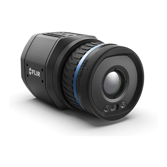
FLIR A400 Series Getting Started
Hide thumbs
Also See for A400 Series:
- User manual (67 pages) ,
- Getting started (48 pages) ,
- User manual (69 pages)
Advertisement
Quick Links
Advertisement

Summary of Contents for FLIR A400 Series
- Page 1 Getting started FLIR A400 series, FLIR A700 series...
- Page 3 Table of contents 1 List of contents ..............1 2 Illustrations .
- Page 4 Printed documentation including username and password for login to the web interface of the camera. Note FLIR Systems reserves the right to discontinue models, parts or acces- sories, and other items, or to change specifications at any time without prior notice.
- Page 5 2 Illustrations Note Explanations of the illustrations are provided in each language section. Figure 2.1 View from the rear, FLIR A400/A700 Figure 2.2 View from the front, FLIR A400/A700 #T810482; r./; mul...
- Page 6 2 Illustrations Figure 2.3 FLIR A400pt/A700pt Figure 2.4 FLIR A400f/A700f Figure 2.5 Typical system overview, Early fire detection #T810482; r./; mul...
- Page 7 2 Illustrations Figure 2.6 Typical system overview, Condition monitoring Figure 2.7 Typical system overview, Research & Development #T810482; r./; mul...
- Page 8 To activate your extended warranty, go to http://support.flir.com/camreg. Note Registration must be completed within 60 days of purchase. 3.3 Download FLIR software FLIR Systems provides freeware and licensed software for image editing, video processing, thermal analysis, and reporting. To download FLIR Thermography software, go to http://www.flir.com/support.
- Page 9 Connect the PoE cable to the camera, and then to a PoE switch on the same network as the computer. The camera is set to use DHCP. On the computer, use FLIR IP Config to identify the camera on the network and change IP settings, if necessary.
- Page 10 Power-I/O connector, A-coded. Antenna. RS232/485 connector, A-coded. Factory reset button. For factory reset modes, refer to the User’s manual of the FLIR A400/A700 series. 3.6.3 View from the front See Figure 2.2 View from the front, FLIR A400/A700, page 2.
- Page 11 Hot spot detection, self-combustible material on conveyor belt, see Figure 2.5 Ty- pical system overview, Early fire detection, page 3. Coal mine conveyor belt. FLIR A410/A710 Smart Sensor camera. Ethernet connector, X-coded. Power–I/O connector, A-coded. Digital output to a PLC.
- Page 12 Checking heat dissipation on PCB during development, see Figure 2.7 Typical system overview, Research & Development, page 4. Computer running FLIR science software, for example FLIR Research Studio. CAT-6 Ethernet cable. Laboratory setup with a FLIR A415/A715 Image Streaming camera.
- Page 13 Customer support http://support.flir.com Copyright © 2020, FLIR Systems, Inc. All rights reserved worldwide. Disclaimer Specifications subject to change without further notice. Models and accessories subject to regional market considerations. License procedures may apply. Products described herein may be subject to US Export Regulations. Please refer to exportquestions@flir.com with any questions.


Need help?
Do you have a question about the A400 Series and is the answer not in the manual?
Questions and answers