Table of Contents
Advertisement
® ® ® ®
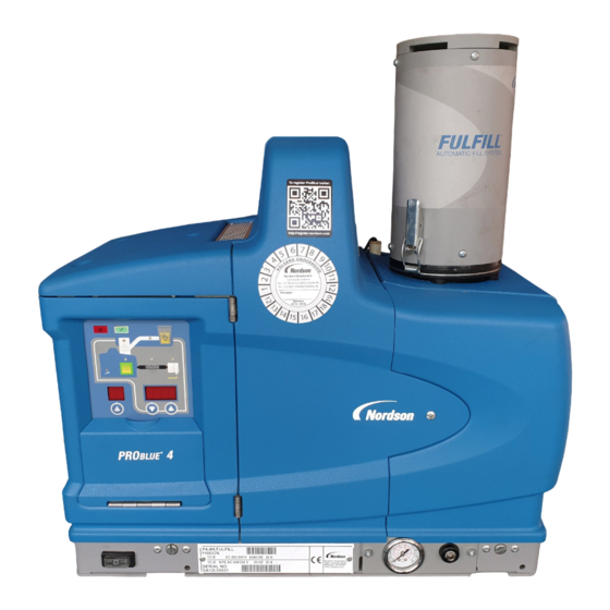
ProBlue
Fulfillt t t t
Integrated Fill System
Customer Product Manual
Part 1101094_02
Issued 01/2013
This document contains important safety information
Be sure to read and follow all safety information in this
document and any other related documentation.
NORDSON CORPORATION • DULUTH, GEORGIA • USA
www.nordson.com
Advertisement
Table of Contents

Related Manuals for Nordson ProBlue Fulfill


Summary of Contents for Nordson ProBlue Fulfill
- Page 1 Integrated Fill System Customer Product Manual Part 1101094_02 Issued 01/2013 This document contains important safety information Be sure to read and follow all safety information in this document and any other related documentation. NORDSON CORPORATION • DULUTH, GEORGIA • USA www.nordson.com...
- Page 2 ContourCoat, CPX, cSelect, Cyclo-Kinetic, DispensLink, Dry Cure, DuraBraid, DuraCoat, DuraPUR, Easy Clean, EasyOn, EasyPW, Eclipse, e.dot+, E-Nordson, Equalizer, EquiBead, FillEasy, Fill Sentry, Flow Coat, Fluxplus, Get Green With Blue, G-Net, G-Site, IntelliJet, iON, Iso-Flex, iTrend, Lacquer Cure, Maxima, Mesa, MicroFin, MicroMax, Mikros, MiniBlue, MiniEdge, Minimeter, Multifill, MultiScan, Myritex, Nano, NexJet, OmniScan, OptiMix,...
-
Page 3: Table Of Contents
......... Part 1101094_02 E 2012 Nordson Corporation... - Page 4 ..........Restoring ProBlue Fulfill Factory Settings .
-
Page 5: Manual Coverage
This manual provides information specific to the installation, operation, and troubleshooting of the integrated fill sub-system (Fulfill) incorporated into your ProBlue adhesive melter. NOTE: For ProBlue Fulfill melters (generation 1) with fill system controls in the sub-base, refer to manual P/N 1081444. Safety Before installing and operating the fill system, read the safety information provided in the melter product manual in Section 1, Safety. -
Page 6: Restrictions To System Use
The Fulfill system extends proven ProBlue adhesive melter technology by providing automatic delivery of solid-formed adhesive to the melter tank. For a complete ProBlue Fulfill integrated fill system, both the melter and an installation kit must be ordered. Figure 1... -
Page 7: Intended Use
ProBlue Fulfill Integrated Fill System Intended Use Same as the melter. Refer to the melter manual. Unintended Use Same as the melter. Refer to the melter manual. Melter Firmware Requirements Operation of the fill system requires that melter firmware version 2.076 or later be installed in the melter. -
Page 8: Modes Of Operation
ProBlue Fulfill Integrated Fill System Modes of Operation The default mode of operation is the automatic mode. When the melter is operating in the automatic mode, the fill system tracks the melter ready signal. When the melter is ready, the fill system is enabled. If the melter status changes to not ready, then the fill system is disabled. -
Page 9: Overview Of Pneumatic And Mechanical Components
ProBlue Fulfill Integrated Fill System Overview of Pneumatic and Mechanical Components Figure 2 Overview of Fulfill system components (A). Adhesive Transfer Hose The adhesive transfer hose connects the suction lance to the lid assembly. The transfer hose conveys adhesive from the adhesive storage bin to the melter tank. -
Page 10: (C). Filter Housing And Lid Assembly
ProBlue Fulfill Integrated Fill System (C). Filter Housing and Lid Assembly The Fulfil lid assembly includes the filter stack, lid, fill tube, baffle, and deflector: The filter stack contains a replaceable filter sock to prevent adhesive fines and powder in the adhesive from being emitted into the ambient air. -
Page 11: Overview Of Electrical Components
ProBlue Fulfill Integrated Fill System Overview of Electrical Components The integrated Fulfill system includes a Fulfill-specific control panel. A refill board located inside the electrical enclosure and a level sensor located inside the tank control fill system operation. (F). Control Panel... -
Page 12: Refill Board
ProBlue Fulfill Integrated Fill System Refill Board See Figure 4. The refill board is located inside the electrical enclosure. Note that: The FAULT, DELAY, and AIR potentiometer functions are controlled through parameters. Refer to Set Up the Fill System under Installation for parameter descriptions. - Page 13 ProBlue Fulfill Integrated Fill System This page intentionally left blank. Part 1101094_02 E 2012 Nordson Corporation...
-
Page 14: Installation
ProBlue Fulfill Integrated Fill System Installation Before installing the fill system, familiarize yourself with Section 3, Installation, in the melter manual. Installation Clearances Figure 5 Minimum installation clearances (top and side views shown; refer to Table 1) Part 1101094_02 E 2012 Nordson Corporation... - Page 15 ProBlue Fulfill Integrated Fill System Table 1 Installation Clearances (see Figure 5) Item Description Required Clearance The distance from the outside edge of a -in. Nordson hose P4 = 370 mm (14.5 in.) to the front face of the melter when a short 90-degree hose P7 = 370 mm (14.5 in.)
-
Page 16: Installation Components
ProBlue Fulfill Integrated Fill System Installation Components In addition to the components contained in the melter installation kit, the Fulfill system is shipped with the components shown in Figure 7. NOTE: These components are shipped inside the adhesive storage bin. -
Page 17: Assemble The Lid Components
ProBlue Fulfill Integrated Fill System Assemble the Lid Components See Figure 8. Install the filter enclosure, filter sock and inlet tube on the tank lid of the Fulfill melter. 1. Remove the three M4 socket-head screws (5) and spacers (6) from the tank lid assembly (7). -
Page 18: Assemble The Transfer Hose, Air Line, And Suction Lance
ProBlue Fulfill Integrated Fill System Assemble the Transfer Hose, Air Line, and Suction Lance See Figure 9. 1. Using one hose clamp, attach the transfer hose (A) to the end of the suction lance (B). 2. Use the remaining hose clamp to attach the transfer hose to the feed system inlet tube (C). - Page 19 ProBlue Fulfill Integrated Fill System Figure 9 Assembling the transfer hose, air line, and suction lance Part 1101094_02 E 2012 Nordson Corporation...
-
Page 20: Set Up The Fill System
Refer to the installation section of the melter manual for the procedures for connecting and setting up inputs/outputs. NOTE: For ProBlue Fulfill melters (generation 1) with fill system controls in the sub-base, refer to manual P/N 1081444. To change a Fulfill system parameter See Figure 10. - Page 21 ProBlue Fulfill Integrated Fill System Table 2 Fulfill System Parameters Parameter Name Values Description Fill Time Delay Default: 60 (seconds) The continuous time delay (in seconds) between when a tank low level condition is Range: 0-1000 (seconds) detected and when the fill system activates.
-
Page 22: Test The Fill System
ProBlue Fulfill Integrated Fill System Test the Fill System The melter is shipped from the factory preprogrammed for automatic refill operation. The factory settings that control the operation of the fill system can be adjusted to meet specific application requirements. Refer to the previous procedure, Set Up the Fill System. -
Page 23: Remove The Inlet Air Deflector (Optional)
In some applications, better performance is achieved without the deflector. NOTE: If the inlet tube is clogging, Nordson Corporation recommends removing the air deflector. See Figure 11. To remove the inlet air deflector, open the tank lid and remove the deflector screws (1) and the deflector (2). -
Page 24: Operation
ProBlue Fulfill Integrated Fill System Operation Once enabled, the fill system immediately begins operation. All that is required to maintain automatic refill operation is to maintain the level of adhesive in the adhesive storage bin. Monitoring Refill Operation Under normal conditions, there is no need for the operator to monitor or intervene in the operation of the fill system. -
Page 25: Clearing A Refill Alarm
ProBlue Fulfill Integrated Fill System Clearing a Refill Alarm NOTE: When the refill alarm output is activated, the melter heaters stay on and the melter ready remote output remains active. 1. Press the Fill System Enable key (4) to disable the fill system and alarm. -
Page 26: Troubleshooting
ProBlue Fulfill Integrated Fill System Troubleshooting If the fill system fails and the condition cannot be corrected, to continue operating the melter (and filling it manually), disable the fill system (ensure that the fill system power key LED is not illuminated). -
Page 27: Restoring Problue Fulfill Factory Settings
ProBlue Fulfill Integrated Fill System Restoring ProBlue Fulfill Factory Settings There are two methods for restoring the melter to the ProBlue Fulfill factory settings: using the “restore saved settings” feature or re-entering the fill system operating parameters. To restore saved settings If you previously saved the melter settings, you can restore them by simultaneously pressing the number 2 key and the Setup key. -
Page 28: Level Sensor Adjustment And Calibration
ProBlue Fulfill Integrated Fill System Level Sensor Adjustment and Calibration The level sensor consists of a level probe and a control box. The level probe has a black line around its diameter near the tip to note the maintained adhesive level. -
Page 29: Baseline Setting
ProBlue Fulfill Integrated Fill System Baseline Setting Upon setting the probe's height, calibrate the level sensor. 1. Remove the threaded plug on the front face of the level sensor control box to reveal the adjustment potentiometer. 2. Fill the tank with adhesive and allow it to melt completely. - Page 30 ProBlue Fulfill Integrated Fill System This page intentionally left blank. Part 1101094_02 E 2012 Nordson Corporation...
-
Page 31: Parts
A dash in this column indicates that the item is an assembly. The number in the Part column is the Nordson part number you can use to order the part. A series of dashes indicates that the part is not saleable. -
Page 32: Melter Assembly Part Numbers
ProBlue Fulfill Integrated Fill System Melter Assembly Part Numbers For a complete ProBlue Fulfill integrated fill system, both the melter and an installation kit must be ordered. Part Description 1100375 Melter, ProBlue Fulfill 4, 2H/G, 200/240V 1100376 Melter, ProBlue Fulfill 4, 4H/G, 200/240V... -
Page 33: Splash-Resistant Installation Kit
ProBlue Fulfill Integrated Fill System Splash-Resistant Installation Kit NOTE: For an illustration of most of the components in this installation kit, refer to the instruction sheet supplied with the kit (P/N 1103791). Visit emanuals.nordson.com to download technical documentation. Part Description... -
Page 34: Lid Assembly Parts
ProBlue Fulfill Integrated Fill System Lid Assembly Parts See Figure 13. Item Part Description Quantity Note — - - - - - - LID,ASSEMBLY,P4F — — - - - - - - LID,ASSEMBLY,P7/10 F — 1099187 S LID,INNER,P4F 1102912 S LID,INNER,P7/10 FILL... - Page 35 ProBlue Fulfill Integrated Fill System TIGHTEN TO 15-20 IN-LBS OF TORQUE TIGHTEN TO 15-20 IN-LBS OF TORQUE TIGHTEN TO TIGHTEN TO 15-20 IN-LBS 15-20 IN-LBS OF TORQUE OF TORQUE TIGHTEN TO 15-20 IN-LBS OF TORQUE TIGHTEN TO 15-20 IN-LBS OF TORQUE...
-
Page 36: Regulator/Solenoid Assembly Parts
ProBlue Fulfill Integrated Fill System Regulator/Solenoid Assembly Parts See Figure 14. Item Part Description Quantity Note — 1098248 REGULATOR/SOL.ASSY,FULFILL — 1093650 S VALVE,SOLENOID,3-WAY,24V,1/4 NPT 1058059 S MUFFLER POLYETHYLENE 1/4" NPT, SATURN 327029 S ELBOW,PIPE,HYD,1/4NPT,BR,BAR 1096668 S REGULATOR/FILTER,40 MIC,1/4 NPT,65 PSIG... - Page 37 ProBlue Fulfill Integrated Fill System Circuit Board and Membrane Panel Service Kits See Figure 15. Item Part Description Quantity Note 1100171 KIT,SVCE,FULFILL,CONTROLS MEMBRANE, P4/P7 1100172 KIT,SVCE,FULFILL,CONTROLS MEMBRANE,P10 1101718 KIT,SVCE,FULFILL,CPU (display/CPU board) 1096221 SERVICE KIT,REFILL CONT.,PROBLUE (refill board) 939995 S Fuse, time-lag, 2A, 5X20MM, ceramic...
-
Page 38: Miscellaneous System Parts
ProBlue Fulfill Integrated Fill System Miscellaneous System Parts See Figures 16-17. Item Part Description Quantity Note 1100558 AMPLIFIER,SENSOR,RECHNER,FULFILL,G2 (level sensor amplifier) 1100015 BRACKET,AMPLIFIER,FULFILL 1100173 KIT,SVCE,FULFILL,SENSOR,150MM W/CONN (capacitive level sensor with 150 mm probe) 1098584 BRACKET,SOLENOID,FULLFILL 1099258 GASKET,PUMP COVER,P4/7,FULLFILL (under pump tower cover) - Page 39 ProBlue Fulfill Integrated Fill System Figure 16 Miscellaneous system parts (1 of 2) Part 1101094_02 E 2012 Nordson Corporation...
- Page 40 ProBlue Fulfill Integrated Fill System Miscellaneous System Parts (contd) Figure 17 Miscellaneous system parts (2 of 2) Part 1101094_02 E 2012 Nordson Corporation...
-
Page 41: Optional Accessories
B: This kit is required if the adhesive transfer hose is longer than the standard length. Refer to the instruction sheet provided with the kit for the installation procedure. C: Extension kits are available if longer hose/air line lengths are needed. Contact your Nordson representative for information. - Page 42 ProBlue Fulfill Integrated Fill System This page intentionally left blank. Part 1101094_02 E 2012 Nordson Corporation...
-
Page 43: Technical Data
ProBlue Fulfill Integrated Fill System Technical Data Fulfill System Specifications The following specifications are specific to the Fulfill integrated fill system. For general ProBlue melter specifications, refer to the melter manual. Parameter Specification Melter operating temperature range 40-205 _C (104-400 _F) -
Page 44: Dimensions
ProBlue Fulfill Integrated Fill System Dimensions Figure 18 Melter dimensions (refer to Table 4; P4 melter shown) Note: For clearances, refer to Installation Clearances under Installation. Table 4 Melter Dimensions Parameter ProBlue 4 ProBlue 7 ProBlue 10 539.1 mm (21.22 in.) 603.2 mm (23.75 in.) - Page 45 ProBlue Fulfill Integrated Fill System 534 mm (21 in.) 1397 mm (55 in.) 940 mm (37 in.) 559 mm 559 mm (22 in.) (22 in.) Figure 19 Adhesive storage bin dimensions and clearances Part 1101094_02 E 2012 Nordson Corporation...
-
Page 46: Wiring Diagram
ProBlue Fulfill Integrated Fill System Wiring Diagram Figure 20 Wiring diagram Part 1101094_02 E 2012 Nordson Corporation... -
Page 47: Ec Declaration Of Conformity
The product specified conforms to the directives and standards described above. Technical File Contact: Dieter Ziesmer Nordson Engineering GmbH Peter Lambert, Senior Vice President Lilienthalstrasse 6 Adhesives Dispensing Systems 21337 Lueneburg GERMANY Date: 14 December 2012 Nordson Corporation S 28601 Clemens Road S Westlake, Ohio 1105311A03 DOC074R4...
Need help?
Do you have a question about the ProBlue Fulfill and is the answer not in the manual?
Questions and answers