
Related Manuals for Nordson Spectrum II Series


Summary of Contents for Nordson Spectrum II Series
- Page 1 Spectrum II Series ™ S2-900 Dispensing System Installation, Operations, and Maintenance Manual P/N 7255741, Rev B...
- Page 3 NOTICE This is a Nordson ASYMTEK publication, which is protected by copyright. Original copyright date 2014. No part of this document may be photocopied, reproduced, or translated to another language without the prior written consent of Nordson ASYMTEK. The information contained in this publication is subject to change without notice.
- Page 4 Manual Conventions Dispensing system labels, buttons and switches, and software menu selections Bold Text and commands appear in this text style [Bracketed Text] [Bracketed Text] indicates a single key or key combination to press on a computer keyboard, such as [Enter] or [Alt + Tab]. Refers to a series of menu bar commands in the Fluidmove software.
-
Page 5: Table Of Contents
Table of Contents Introduction ............................1-1 Overview ..........................1-1 System Description ....................... 1-1 Safety First ..........................1-1 Manuals ..........................1-2 Training ..........................1-2 1.5.1 Student Certification ....................1-2 1.5.2 Student Registration ....................1-2 Supported Dispensing Fluids ....................1-2 S2-900 Series Overview ....................... 1-3 Supported Applications ...................... - Page 6 1.11.9 Rear Cabinet ......................1-24 1.11.10 Rear Panel Connections ..................1-25 Safety ..............................2-1 Overview ..........................2-1 Facility Requirements ......................2-1 System Use ........................... 2-1 2.3.1 Intended Use ......................2-1 2.3.2 Misuse ........................2-2 Basic Safety Precautions and Practices ................2-2 2.4.1 Safety of Personnel ....................
- Page 7 Operation ............................4-1 Overview ..........................4-1 Safety First ..........................4-1 Powering on the Dispensing System ..................4-2 Starting Fluidmove for Windows ................... 4-3 Installing the Dispensing Valve ..................... 4-4 4.5.1 Valve Software Setup ....................4-4 4.5.2 Valve Pneumatic and Electrical Connections ............4-4 Adjusting the Air Pressure .....................
- Page 8 Focusing the Camera ......................5-2 Calibrating the Camera ......................5-5 Adjusting the Service Station Height ..................5-7 Calibrating the Scale ......................5-8 Adjusting the Z-Head Counterbalance Force ..............5-11 5.10 Adjusting the Height Sensor Probe (Option) ............... 5-13 5.11 Adjusting the Board Sensors ....................5-15 5.11.1 Standard Operation and Tuning ................
- Page 9 Troubleshooting ..........................7-1 Overview ..........................7-1 Safety First ..........................7-1 Record Keeping ........................7-1 Basic System Troubleshooting ....................7-2 7.4.1 System Power ......................7-2 7.4.2 System Accuracy ...................... 7-3 7.4.3 Fluidmove Startup ....................7-3 7.4.4 Pneumatic ........................ 7-4 7.4.5 Dispense Head Controller Connections and Functions ........... 7-5 7.4.6 Mechanical/Tactile Height Sensor ................
- Page 10 System Dimensions ....................... 9-4 9.4.1 S2-900 ........................9-4 9.4.2 S2-9XXC ........................9-6 Stability Analysis ........................9-8 Appendix A Material Safety Information ..................A-1 Introduction ..........................A-1 Safety Data Sheets ....................... A-1 A.2.1 Multemps PS NO 2....................A-2 A.2.2 Moly-Graph Extreme Pressure Multi-Purpose Grease ..........A-8 A.2.3 NSK Clean Grease LG2 ..................A-15 Appendix B...
- Page 11 Table of Figures Figure 1-1 S2-900 Front View ......................1-13 Figure 1-2 S2-9XXC Cleanroom Configuration with Pre- and Post-Queue Stations ......1-14 Figure 1-3 Dispensing Area ....................... 1-15 Figure 1-4 Service Station ........................1-16 Figure 1-5 Scale Assembly ........................ 1-17 Figure 1-6 Front Panel ........................
- Page 12 Figure 4-15 Camera Lighting Adjustment .................... 4-20 Figure 4-16 Machine Offset Parameters Window ................4-22 Figure 4-17 Machine Offsets ........................ 4-23 Figure 4-18 Offsets Complete ......................4-24 Figure 4-19 Fluidmove Error Message 30694 ..................4-24 Figure 4-20 Production Window - Teaching Safe Z Height ..............4-25 Figure 4-21 Teaching Safe Z Height ....................
- Page 13 Figure 5-24 Heater Control Window ....................5-22 Figure 5-25 Heater Parameters Window ..................... 5-22 Figure 5-26 Local Machine Offsets - Heater Offsets ................5-24 Figure 5-27 Input Temperature Offset Value ..................5-24 Figure 5-28 Heater Setup Window - Controlled Process Heat Enabled ..........5-25 Figure 5-29 Heater Control Loop Parameters Window - Main Tab .............
- Page 14 Table of Tables Table 1-1 Recommended Applications ....................1-3 Table 1-2 Standard/Optional Features ....................1-4 Table 2-1 Safety Warning Labels ....................... 2-6 Table 2-2 Laser Height Sensor Specifications .................. 2-13 Table 2-3 Beacon Color Indications ....................2-18 Table 4-1 Dispensing Head Jog Controls: Jog Distance and Velocity ..........
-
Page 15: Introduction
This manual is intended primarily as a reference for process engineers and service technicians. Production operators and those unfamiliar with Nordson ASYMTEK products may also find this manual useful as a general introduction to the system. This section introduces the S2-900 Dispensing System and covers the... -
Page 16: Manuals
California, USA and in Amherst, Ohio, USA and are conducted in a classroom and lab environment. On-site training at a Nordson facility offers several benefits: students are free from the distractions of work and get actual hands-on time with the machines. Students rebuild machine subassemblies, troubleshoot real problems and learn a variety of setup techniques. -
Page 17: S2-900 Series Overview
S2-9XXC systems are not compatible with the IntelliJet ® Jetting System. Supported Applications Contact Nordson ASYMTEK for applications not listed. Table 1-1 Recommended Applications S2-900 S2-900P w/ NJ-8 or DJ-9500 w/ IntelliJet... -
Page 18: S2-900 Series Features
S2-900 Series Features Table 1-2 Standard/Optional Features = Standard = Option NA = Not Available System Features ESR = Special Order S2-900 S2-900P S2-9XXC Computer and Software Laptop with Windows Operating System Fluidmove 6.X or later ... -
Page 19: Feature Description
1.10.2 CAD Import Software Nordson ASYMTEK’s CAD Import software imports CAD data in an ASCII file (in the format of a comma separated - CSV - text file) from a component placement machine to simplify Fluidmove program generation. -
Page 20: Cleanroom
S2-900 system unloads a part from the dispense station to the downstream machine. 1.10.7 Dispensing Valves The S2-900 Series Dispensing Systems support the following Nordson ASYMTEK jets and valves: ® DJ-9500 Series DispenseJet DV-02 Pinch Tube Valve •... -
Page 21: Dual-Simultaneous Dispensing
1.10.9.1 Manual Dual-Simultaneous Dispensing (MDS) The Manual Dual Simultaneous (MDS) option supports the use of two identical Nordson ASYMTEK DJ-Series or DV-Series dispensing valves, mounted on a single Z-head, to simultaneously dispense fluid at two locations. It is ideal for applications where dispense accuracy (placement and volume) is less critical. -
Page 22: Height Sensor
Specialized circuitry automatically controls the duration of laser emission, preventing measurement errors due to surface color and texture variations. Three LHS models are available. Contact Nordson ASYMTEK to determine the best fit for your application requirements. An optional Mechanical/Tactile Height Sensor is also available. -
Page 23: Low Pressure Sensor
1.10.16.2 Low Fluid Sensor Hardware An optional capacitive or magnetic sensor is available to detect low fluid conditions. The sensor activates the light beacon and causes the software to issue a low fluid alert message. 1.10.17 Low Pressure Sensor The Low Pressure Sensor can be manually set for a pressure from 10 to 100 psi (69 to 689 kPa). The sensor will issue a signal when main air pressure is lower than the manual set point. -
Page 24: Programmable Tilt And Rotate
1.10.23 Programmable Tilt and Rotate The Programmable Tilt and Rotate (PTR) option provides fully automated valve tilting in both the X and Y-axis, with an integrated rotation function in the motorized tilt arm for systems configured with the IntelliJet, DJ-9000, or DJ-9500 dispensing valve. The PTR bracket mounts on the dispensing head in place of the standard dovetail mount. -
Page 25: Vision System
1.10.28 Vision System The vision system includes a digital camera, light source and laptop computer. The software consists of Fluidmove software and its pattern recognition engine. The camera communicates bi-directionally to the host computer via Gigabit Ethernet. The Pattern Recognition System allows the definition of both global and local fiducials. Global fiducials compensate for low-tolerance fixtures. -
Page 26: System Illustrations
1.11 System Illustrations The figures in this section show views and features of the dispensing system. Callouts locate major components, options, and switches seen in each illustration. Detailed operating instructions for some of these features are treated in other sections of this manual. System features are shown in Figure 1-1 through Figure 1-11. -
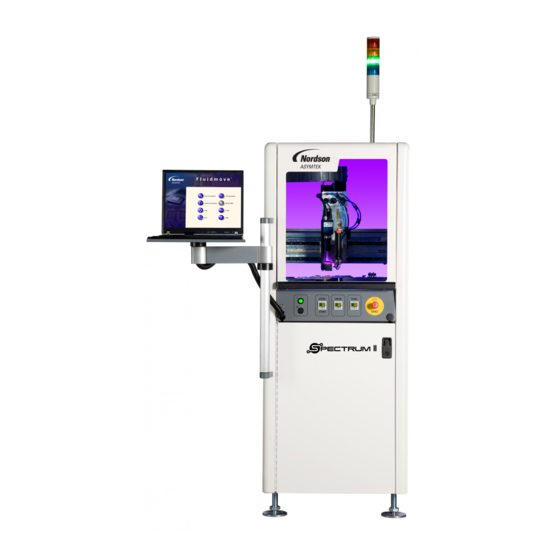
Page 27: Figure 1-1 S2-900 Front View
Figure 1-1B S2-900 with Optional Pre- and Post-Queue Stations Item Name Description The Light Beacon is a device that displays system status and can warn Light Beacon the operator when fault conditions exist. Dispensing Area 1.11.2 Dispensing Area ON and OFF Buttons, Emergency Stop, and Grounding Strap Jacks Front Panel are located on the Front Panel. -
Page 28: Figure 1-2 S2-9Xxc Cleanroom Configuration With Pre- And Post-Queue Stations
Item Name Description The Ultra Low Particulate Air (ULPA) Filter provides a downward ULPA Filter particle-free air column within the dispense area. The S2-9XXC Cleanroom system is equipped with a stainless steel Enclosure enclosure. Figure 1-2 S2-9XXC Cleanroom Configuration with Pre- and Post-Queue Stations 1-14 Introduction... -
Page 29: Dispensing Area
1.11.2 Dispensing Area Item Name Description The compact, high resolution, black and white camera and lens are Vision System part of the Vision System. They are mounted on the dispensing head and are used to view work surfaces. Pneumatic and Electrical The bulkhead includes valve, low fluid sensor, and air pressure Connections connections. -
Page 30: Service Station
1.11.3 Service Station Item Name Description The Dispense Tile is a ceramic tile dispensed upon during system Dispense Tile offset routines. The Tactile Needle Sensor measures the offset between the Tactile Needle Sensor needle/nozzle and the height sensor. The Purge Station consists of a small reservoir that contains a disposable plastic cup and is attached to a vacuum generator. -
Page 31: Scale
1.11.4 Scale Scale Assembly Scale Assembly with Shutter (Cleanroom) Item Name Description The scale measures the weight of dispensed fluid and sends the information to the Fluidmove software for mass flow calibration. The Scale Assembly scale is standard on S2-900P systems and an option on S2-900 systems. -
Page 32: Front Panel
1.11.5 Front Panel Item Name Description Grounding straps worn by the operator plug into this jack to prevent Grounding Strap Jack electrostatic discharge (ESD) damage to workpieces during maintenance operations. Computer Connection Connects the dispensing system to the laptop computer. The Front EMO is a built-in safety feature located on the front panel Front EMO of the dispensing system. -
Page 33: Front Cabinet
1.11.6 Front Cabinet S2-900 Series Systems S2-900P Series Systems NOTE The S2-900P Series features programmable fluid and valve pressure. Air pressure is set through the Fluidmove software. This feature is an option on the S2-900 Series Systems. Item Name Description Vacuum Air Regulator Controls the air pressure supplied to the vacuum air. -
Page 34: Rear View
1.11.7 Rear View Figure 1-8A S2-900 Rear View (30A Power Manager shown) 1-20 Introduction... -
Page 35: Figure 1-8 Rear View
Fluid/Valve Conveyor/Heater Pneumatics Pneumatics Figure 1-8B Main Air Regulator and Gauge Sets (Close-up) Item Name Description The system is equipped with two Main Air Regulators and Gauges. They control the air pressure supplied to all other system regulators. The Main Air Regulator regulators contain built-in air filter and water traps to ensure that only and Gauge clean, dry air enters the system. -
Page 36: Rear View Open
1.11.8 Rear View Open Figure 1-9A S2-900 Rear View Open 1-22 Introduction... -
Page 37: Figure 1-9 Rear View Open
Figure 1-9B Rear View Open (S2-900P with Pre-Queue and Post-Queue Stations) Item Name Description The Upper E-Pan houses the Dispense Head Controller, Z-Axis Servo Upper E-Pan Amp, and Applicator Pneumatics. The Lower E-Pan houses the Main PWA, X-Y Axis Servo Amps, Main Air Lower E-Pan Pneumatic Valves, and Conveyor Pneumatic Valves. -
Page 38: Rear Cabinet
1.11.9 Rear Cabinet Item Name Description The Conveyor/Heater Module receives power from the Power Manager and supplies AC power to the substrate heaters in the dispensing area. Conveyor/Heater It also controls all conveyor functions (motors, sensors, pneumatics, Module etc.). If your system is equipped with dual conveyors, there will be two (systems with heat) Conveyor/Heater Modules. -
Page 39: Rear Panel Connections
1.11.10 Rear Panel Connections S2-900/S2-900P S2-9XXC Item Name Description Allows for SMEMA communication between Conveyor 2 and a CV2 Downstream downstream machine such as an unloader. Allows for SMEMA communication between Conveyor 2 and an upstream CV2 Upstream machine such as a loader. Loader/Up Not used on this machine. -
Page 41: Safety
Requirements. If you have any questions, please contact Nordson ASYMTEK Technical Support. System Use 2.3.1 Intended Use Use of Nordson ASYMTEK equipment in ways other than those described in the documentation supplied with the equipment may result in injury to persons or damage to property. Safety... -
Page 42: Misuse
2.3.2 Misuse Some examples of misuse of the equipment include: Using incompatible materials • Making unauthorized modifications • Removing or bypassing safety guards or interlocks • • Using incompatible or damaged parts Using unapproved auxiliary equipment • Operating equipment in excess of maximum ratings •... -
Page 43: Material Safety
• Do not touch the dispensing head or other moving parts while the dispensing system is operating. To prevent burn injury, wear thermal gloves when working around heater tooling and fluid • heaters. If your system is equipped with a laser height sensor, use extreme care to avoid looking •... -
Page 44: Preventing Dispensing System And Workpiece Damage
Immediately contain and clean up any caustic or conductive fluid spills as recommended in • the material manufacturer’s SDS. If fluid gets into internal portions of the machine, immediately contact Nordson ASYMTEK Technical Support. Follow all recommended system maintenance procedures. •... -
Page 45: Lifting And Transport Precautions
Lifting and Transport Precautions 2.6.1 Considerations Before attempting to lift a load, personnel should take into consideration the following factors: • Does the load display a lift hazard warning label as shown below? Is lifting and transporting equipment available that might make the task safer and easier? •... -
Page 46: Safety Warning Labels
Safety Warning Labels Safety warning labels on the S2-900 Series Dispensing System point out potentially hazardous areas and remind personnel to take necessary safety precautions. Table 2-1 describes safety warning labels that may be on the dispensing system. WARNING! Comply with all safety warning labels or serious injury to personnel or damage to the dispensing system may occur. - Page 47 Table 2-1 Safety Warning Labels (Continued) Label/ Part Warning Type Hazard Symbol Number 196666 Warns that the labeled component is heavy Heavy Object and can cause muscle strain or back injury to (Lifting Hazard) personnel trying to lift it. 70-0118-00 70-2150-00 Warns personnel of potentially hot components and surfaces.
-
Page 48: Figure 2-1 Safety Warning Labels (Front Cover)
Item Description Read Manual Label Emergency Machine Off Symbol Figure 2-1 Safety Warning Labels (Front Cover) Item Description Laser Radiation Warning Label (if Class 2 Laser Height Sensor present) Hot Surface Label (if heaters present) Figure 2-2 Safety Warning Labels (Front Inside Panel) Safety... -
Page 49: Figure 2-3 Safety Warning Labels (Z-Head)
Item Description Laser Radiation Warning Label (if Class 2 Laser Height Sensor present) Figure 2-3 Safety Warning Labels (Z-Head) Safety... -
Page 50: Figure 2-4 Safety Warning Labels (Conveyor)
Item Description Hot Surface Label (if heaters present) Moving Parts Present Label Figure 2-4 Safety Warning Labels (Conveyor) Item Description Clean Dry Air Warning Label Figure 2-5 Safety Warning Label (Rear) 2-10 Safety... -
Page 51: Figure 2-6 Safety Warning Labels (Rear Cabinet)
Item Description Hand Entanglement Label Hot Surface Label Figure 2-6 Safety Warning Labels (Rear Cabinet) Item Description Electrical Warning Label Figure 2-7 Safety Warning Labels - Power Manager Safety 2-11... -
Page 52: Residual Safety Risks
Residual Safety Risks Safety Hazard Risk Area A high risk crushing hazard is created by the movement of the conveyor. DO NOT reach into the conveyor while the system is operating. Keep hands away from this area unless the system power is off. -
Page 53: Laser Radiation
2.10 Laser Radiation WARNING! If the system is equipped with a Class 2 laser height sensor, the following safety precautions must be observed in addition to the basic system safety precautions: • Operate the laser height sensor in accordance with the operator’s manual included with the equipment. -
Page 54: Emergency Shutdown
2.11 Emergency Shutdown In the event of an emergency or malfunction, press the EMO button. The S2-900 Series has two EMO buttons. The EMO buttons are the large red buttons located on the front panel and the rear of the dispensing system (Figure 2-10). -
Page 55: Emergency Shutdown Situations
2.11.1 Emergency Shutdown Situations As a minimum, activate the EMO in the following situations: If anyone is in immediate danger of being injured by moving parts, hazardous materials, or • electrical shock. If valuable dispensing system components or the workpieces are in danger of being damaged. •... -
Page 56: Service Shutdown
2.13 Service Shutdown Before performing any service or parts replacement, the dispensing system should be shut down as follows: 1. Shutdown the dispensing system as described in 4.13 System Shutdown. 2. Perform a “Lockout/Tagout of Electrical and Pneumatic Energy” as described below. 2.14 Lockout/Tagout of Electrical and Pneumatic Energy Companies may differ in their Lockout/Tagout (LOTO) procedures and requirements, and it is the responsibility of the end user to determine compliance with local safety procedures. -
Page 57: Figure 2-13 Electrical/Pneumatical Lockout/Tagout
6. Install an approved lockout clamp and keyed lock onto the pneumatic fitting so it cannot be reconnected to the main air regulator, and attach an approved tag. Ensure the owner, date, reason, and estimated time to repair are clearly marked on the tag. ... -
Page 58: Light Beacon
2.15 Light Beacon The Light Beacon is a device that displays system status and can warn the operator when fault conditions exist. The beacon has red, yellow, green, and blue lights that can be solid or flashing. The beacon also has an audible alarm. -
Page 59: Installation
Facility Requirements To ensure optimal performance and safety, it is necessary to install the dispensing system in a facility that meets the requirements. If you have any questions about facility requirements, please contact Nordson AYSMTEK Technical Support. See 9.2 Facility Requirements for detailed information. -
Page 60: Uncrating And Placing The Dispensing System
1. Check the “Tip & Tell” and "Shockwatch" devices, both on the outside of the shipping crate and on the dispensing system, to make sure that the dispensing system has not been dropped or tipped. If any of these devices has been activated, contact Nordson AYSMTEK. ... -
Page 61: Figure 3-2 Adjusting The Levelers
5. Remove the two 1/2-inch hex head screws clamping the four shipping brackets to the levelers. 6. When the four shipping brackets have been removed, slide the forklift forks under the front of the dispensing system between the levelers (feet). Use the forklift to gently lift the dispensing system off of the crate. -
Page 62: Unpacking The Dispensing Chamber
10. Remove bag and plastic wrap from the machine. NOTE Location of packaging materials to be removed is indicated by the presence of red warning tags. 11. Remove all shrink-wrap and other packing material from the perimeter of the dispensing system. -
Page 63: Figure 3-3 Removing The Front Cover
Figure 3-3 Removing the Front Cover 8. If the system is equipped with a scale, loosen the strap covering the scale and remove the warning tag from the scale unit. Do not remove the strap. The strap may be needed when moving or shipping NOTE machine. -
Page 64: Leveling The Dispensing System
Leveling the Dispensing System WARNING! This procedure should only be performed by a trained service technician. The system should be shut down for service before performing this procedure. 2.13 Service Shutdown. To level the dispensing system: 1. Place the box level on the X-axis linear guide (Figure 3-5). Figure 3-5 Leveling the X-Axis 2. -
Page 65: Figure 3-6 Leveling The Y-Axis
4. Place the box level along the Y-axis linear guide (Figure 3-6). Figure 3-6 Leveling the Y-Axis 5. Observe the position of the bubble within the level’s window. The bubble should be centered, indicating dispensing system is level from front-to-back. -
Page 66: Setting Up The Service Station
Setting Up the Service Station The Service Station consists of both the scale station and purge station. The scale is standard on S2-900P dispensing systems and an option on the S2-900 dispensing systems. To setup the Service Station: 1. Place the scale lid, cup, pedestal and breeze shield on the scale station (Figure 3-7). Figure 3-7 Setting up the Scale Station 2. -
Page 67: Installing The Light Beacon
Installing the Light Beacon 1. Remove the Light Beacon from the storage area behind the front door panel. 2. Remove the dispensing system top cover (Figure 3-9A). 3. Attach it to the top panel using the four (4) screws temporarily installed (Figure 3-9A). 4. -
Page 68: Installing The Laptop Computer
Locate C:\Asymtek\Recovery\SNXXXXX.ACL. b. Compare the serial number located in the name of the ACL file with the serial number on the dispensing system (Figure 3-10). If the numbers are not the same, contact Nordson AYSMTEK Technical Support. Item Description... -
Page 69: Figure 3-11 Aligning The Laptop Computer To The Tray
10. With the laptop lid closed, align the computer with the covers so that no gaps exist on the left side or the back edge. The laptop is adhered to the tray with a hook and loop fastener. Align the laptop ... -
Page 70: Anchoring The Dispensing System
3.11 Anchoring the Dispensing System To prevent movement that could cause injury to personnel and damage to the dispensing system and facility, each dispensing system leveler (foot) should be anchored to the floor with two bolts (Figure 3-12). The anchor joint (the point between each anchor bolt and the floor) must be able to withstand at least 220 lbs (100 kg) of pullout force. -
Page 71: Connecting The Power And Air Supply
3.12 Connecting the Power and Air Supply The following procedures should only be performed by a trained WARNING! service technician. Tools and Materials Needed Main Power Cable • Facility Air Hose • To connect the system to facility power: 1. Locate the main power cable, included in the accessories crate. 2. -
Page 72: Figure 3-14 Connecting The Facility Air Supply
To connect the system to the facility air supply: Make sure that facility air pressure meets the requirements specified in CAUTION! Requirements. Higher pressures will damage the dispensing system. 9.2 Facility 1. Locate the facility quick-disconnect air hose (Figure 3-14). 2. -
Page 73: Operation
Operation Overview The sections that follow describe the general sequence of actions necessary to power on and shutdown the dispensing system; and to write and run a new dispensing program. References to Fluidmove are included as a guide. For detailed information on Fluidmove, please refer to the Fluidmove User Guide. This section covers the following topics: Powering on the Dispensing System Valve Offsets... -
Page 74: Powering On The Dispensing System
Powering on the Dispensing System 1. Verify that the main power cord is connected to the main power inlet and the facility power source. 2. Verify that the facility air is at the recommended pressure level and connected to the main air 3.12 Connecting the Power and Air Supply . -
Page 75: Starting Fluidmove For Windows
Starting Fluidmove for Windows The Fluidmove startup procedure assumes that the computer is ON and running Windows. To start Fluidmove for Windows: 1. Click on or double-click the icon on the Windows Start > Programs > Fluidmove Fluidmove desktop. When Fluidmove starts, it will check to see that all the Input and Output (I/O) devices for ... -
Page 76: Installing The Dispensing Valve
Installing the Dispensing Valve Slide the dovetail bracket (included with the dispensing valve) into the valve mounting bracket on the Z-axis face plate. Tighten with the 4mm hex wrench. 4.5.1 Valve Software Setup Refer to the applicable valve manual or Fluidmove Online Help for software configuration instructions. 4.5.2 Valve Pneumatic and Electrical Connections Standard valve pneumatic and electrical connections are shown in Figure 4-3. -
Page 77: Adjusting The Air Pressure
Adjusting the Air Pressure 4.6.1 Air Regulators and Gauges Air pressure is set manually at the regulator or in the Fluidmove software if the E/P (electronically controlled 4.6.4.2 Electronic Pressure Control Utility pneumatic) regulators option is installed. See for instructions on using the E/P option. -
Page 78: Adjusting The Tooling Air Pressure
4.6.3 Adjusting the Tooling Air Pressure The Tooling Air Pressure regulates air supplied to the stop pins and lift tables. The regulator receives air from the main air regulator located on the back of the dispensing system. 1. Locate the Tooling Air Pressure Regulator adjustment knob in the front cabinet (Figure 4-5). -
Page 79: Adjusting The Cooling/Coaxial, Valve, And Fluid Air Pressure
4.6.4 Adjusting the Cooling/Coaxial, Valve, and Fluid Air Pressure 4.6.4.1 Manual Regulator Adjustment 1. Locate the Cooling/Coaxial, Valve, and Fluid Pressure Regulator adjustment knobs in the front cabinet (Figure 4-6). For accurate pressure adjustment, lower the pressure below the desired level and then ... -
Page 80: Figure 4-7 E/P Utility
4.6.4.2 Electronic Pressure Control Utility The S2-900P features programmable fluid and valve pressure. Electro pneumatic regulators control the valve pressure, fluid pressure and cooling/coaxial pressure. These regulators have been integrated into the platform. All the pressure set point values are set through Fluidmove (as opposed to manual regulators). This reduces possibility of operator error when setting the regulators manually. -
Page 81: Figure 4-8 Fluid Manager - Air Pressure Settings
Using the Air Pressure Settings in the Fluid Manager: 1. In the Fluidmove Main Menu select Configuration > Setup Fluid Manager > Air tab (Figure 4-8). Pressure Settings 2. Click to select the appropriate setting and enter the desired value. 3. -
Page 82: Adjusting The Vacuum Control
4.6.5 Adjusting the Vacuum Control The Vacuum Control (Figure 4-6) allows low viscosity fluids to be consistently dispensed without dripping between cycles. The vacuum exerts a negative pressure (suckback) on the fluid, thereby decreasing dripping. To adjust the Vacuum Control: 1. -
Page 83: Jog Window
Jog Window When necessary, an operator can use Fluidmove Jog Controls to reposition the dispensing head in the X-, Y-, and Z-axes, adjust conveyor rail width, and reposition the workpiece X-axis location on the conveyor. These jog controls can be operated using the touchpad to click on-screen buttons, or by pressing key combinations on the keyboard. -
Page 84: Dispenser Jog Controls
4.7.1 Dispenser Jog Controls 1. Click on the Radio button to activate the dispensing head jog controls. Dispenser 2. Dispensing head jog controls (Figure 4-12) operate as follows: On the X-Y control panel, the arrows pointing to the Left move the dispensing head to ... -
Page 85: Figure 4-12 Dispenser Jog Controls
Item Description Item Description Target Box Locations Buttons Target Box Position Indicator (+) Dispenser Radio Button Z-Axis Controls X-Axis Controls Home Button Y-Axis Controls Figure 4-12 Dispenser Jog Controls 3. Click on to close the Jog Window. Exit When you close the jog widow, the last selected jogging device (Dispenser, ... -
Page 86: Conveyor Jog Controls
4.7.2 Conveyor Jog Controls 1. Click on the radio button to activate the Conveyor 1 jog controls. Conveyor 1 2. Conveyor jog controls (Figure 4-13) operate as follows: On the X-Y control panel, the arrows pointing to the Left move the conveyor belt to the ... -
Page 87: Table 4-2 Conveyor Jog Controls: Jog Distance
Table 4-2 Conveyor Jog Controls: Jog Distance Movement Distance Axis mm (inch) 0.0254 (0.001) 1.27 (0.0500) 0.0254 (0.001) 1.27 (0.0500) Notes: (1) Default distances. Refer to the Fluidmove User Guide or Fluidmove Online Help to modify jog distances. (2) Distance per mouse click on the arrow button. 4.7.2.1 Dual Conveyor Systems If the dispensing system is equipped with dual conveyors, the Conveyor 2 radio button will be active. -
Page 88: Table 4-3 Jog Control Commands
Table 4-3 Jog Control Commands Name Dispensing Head Response Conveyor Response Clicking in the Target Box moves the Target Box dispensing head to the corresponding position in the dispensing area. Moves the Dispensing Head as follows: Moves the rear Conveyor Rail as follows: Slow Backward (small increments) Slow Backward (small increments) Y-Axis Controls... -
Page 89: Using The Keyboard
4.7.3 Using the Keyboard To jog the dispensing head and conveyor using keyboard commands: 1. Press [Ctrl + J] to open the Fluidmove Jog Window. 2. Using the mouse, click on the radio button to activate the dispensing head jog Dispenser controls, the radio button to activate the Conveyor 1 jog controls or the... -
Page 90: Camera Operation
Camera Operation The S2-900 Series features a Dalsa-Coreco Genie M640 digital 640 x 480 pixel camera. It communicates bi-directionally to the laptop computer via Gigabit Ethernet. The camera is configured to run at 60 full frames per second. A frame can be transferred in 16.67 milliseconds. The S2-900P is configured with Monocle™... -
Page 91: Lighting And Color Adjustment
4.8.2 Lighting and Color Adjustment The light intensity and color level can be adjusted to optimize the view of your workpiece. Refer to Section 5 - Calibration and Adjustment for instructions on focusing and calibrating the camera. Except for lighting adjustments and lens replacement, all other configuration and CAUTION! adjustments should only be performed by a trained service technician. - Page 92 Item Description Red Light Adjustment Slide Green Light Adjustment Slide Blue Light Adjustment Slide Jog Controls Figure 4-15 Camera Lighting Adjustment 4-20 Operation...
-
Page 93: Valve Offsets
Valve Offsets Fluidmove provides a semi-automated routine called Valve Offsets to establish machine offset parameters. This setup procedure is vision assisted to ensure the front door remains closed. The user proceeds through a list of steps to teach the camera offset, the Safe Z Height and the locations for the scale and purge stations and the test substrate. - Page 94 To perform a Camera Assisted Scripted Valve Offsets routine: Make sure the Vision System has been calibrated before performing this routine. Refer to NOTE 5.6 Calibrating the Camera. 1. Clear the work area of any obstacles that might interfere with dispensing head movement. 2.
- Page 95 5. In the Main Window, select Configuration > Machine Offsets > Scripted Valve Offsets The Machine Setup Window opens (Figure 4-17). The tasks in the window vary depending on the setup script selected. 6. Verify that the correct script file is selected. The current script file is indicated at the top of the Machine Setup window.
- Page 96 11. When the message appears notifying you that the offsets routine is complete, click on Figure 4-18 Offsets Complete 12. Click in the Machine Setup window. Exit If you end the routine prematurely, you will receive an error message (Figure 4-19). Click NOTE to exit the routine and save the completed tasks or click on to continue.
-
Page 97: Safe Z Height
4.9.1 Safe Z Height Safe Z Height is determined by choosing a height that ensures the needle, height sensor, or any part of the dispensing head does not collide with any obstacles while traveling around the dispensing area. Safe Z Height is the height below which the tip of dispensing head cannot go when moving from one set of coordinates to another during operation. - Page 98 Figure 4-21 Teaching Safe Z Height 4. Move the dispensing head over a workpiece fiducial. 5. Raise or lower the dispensing head until it reaches a Safe Z Height. 6. Click on Teach The Safe Z Height value will be recorded in the value textbox. ...
-
Page 99: Creating A New Program
4.10 Creating a New Program This section briefly covers the steps required to create a new dispensing program. For detailed instructions, refer to the Fluidmove User Guide or Online Help. NOTE The following procedures assume that the dispensing system is on and Fluidmove is running. -
Page 100: Performing Valve Offsets
4.10.2 Performing Valve Offsets If valve offsets have not been defined for the current valve, a new needle/nozzle has been installed, or hardware locations have changed, a Valve Offsets procedure must be performed. See 4.9 Valve Offsets. 4.10.3 Loading the Workpiece 1. -
Page 101: Teaching Workpiece Origin
2. To create a new program, select from the menu bar or click on the File > New Program icon on the toolbar. Wizard This action clears the work area, loads the default fluid and heater files, and opens the ... -
Page 102: Teaching Fiducials
4.10.6 Teaching Fiducials A fiducial is a distinct shape or object on the workpiece. Fluidmove uses fiducials for location reference. If your programming options are set to have one or more fiducials, Fluidmove will prompt you to teach the target points on the workpiece. Choose images that are identical from part to part and in the same location. - Page 103 4.10.7.1 Setting up the Fluid Manager The Fluid Manager contains information about the dispensing fluid. The Fluid Manager settings are saved in the fluid file (.FLU) attached to the program and automatically loaded with the program. This helps to ensure that the correct dispensing parameters are used each time the program is run. To setup the Fluid Manager: 1.
- Page 104 4.10.7.2 Dot Parameters You can control the size and accuracy of dot dispensing by setting dot parameters. You may define up to ten different dot styles. The dot style is selected when entering a dot dispensing instruction into your program. Dot parameters are divided into three categories according to when each parameter is implemented during the dispensing process.
- Page 105 4.10.7.3 Line Parameters Line Parameters offer greater control over line thickness and ensure clean dispensed lines. You may define up to ten different line styles. Each style may have different parameters. You may set line parameters for lines, weight control lines, arcs, circles, rectangles, and area fills. The line style is selected when entering a dispensing instruction into your program.
-
Page 106: Setting The Heaters
4.10.8 Setting the Heaters If your dispensing process requires needle or tooling heat, you need to set the heater temperature and parameters. Both needle and tooling heat parameters are set in the Fluidmove software and saved with the dispensing program. 4.10.8.1 Heater Setup 1. - Page 107 The operator can turn the heaters ON and OFF and monitor their function. However, only authorized personnel should set heater parameters. NOTE Contact your applications engineer or Nordson ASYMTEK Technical Support for information about setting heater parameters for your particular application. To set the heater tooling temperature: 1.
- Page 108 Item Description Item Description Heater Loop - OFF Temperature Set Point Column Heater Loop - ON Present Temperature Value Column Channel (Loop) Name Column Message Column Figure 4-31 Heater Control Window 3. To set the heater temperature and parameters, double click on a channel (loop) name. The heater parameters window opens (Figure 4-32).
- Page 109 To turn on the heaters: 1. Turn on a heater by double clicking the icon in the On/Off column in the Heater Control Window (Figure 4-31). A yellow and red icon indicates the heater is ON. A gray icon indicates the heater is OFF.
-
Page 110: Entering Program Commands
4.10.9 Entering Program Commands Program commands dictate the actions to be performed. They may consist of maintenance functions as well as dispensing instructions. Each command has a line number and the program is executed sequentially. You may rearrange program commands by cutting and pasting them. Ultimately, you want to program the workpiece so that the commands are executed in the fastest way possible. - Page 111 4.10.9.1 Program Commands Toolbar Dispensing Elements Inserts a Program Comment Disable/Enable Instruction Inserts a Send Command into your program Create a Pattern Inserts Process Commands into your program Inserts Procedures into your program Inserts Motion Commands into your program Inserts timer- related functions into your program Conveyor...
- Page 112 4.10.9.2 Dispensing Elements Toolbar There are several fundamental dispensing elements and patterns that form the foundation for all dispensing applications. These include lines, dots, circles, rectangles, area fill, etc. When you select from the Program Commands Toolbar, a Teach Window opens. The Teach Dispensing Elements Window contains the Dispensing Elements toolbar (Figure 4-35).
- Page 113 4.10.9.3 Dual Conveyor Programming Fluidmove programming differs slightly for Dual Lane Dispensing Systems. There is only one program (workpiece) origin for both conveyors. In addition, all program commands must be placed in a Conveyor Block. Program commands for both conveyors may be placed directly in the Workpiece pattern. When placing the commands directly in the Workpiece pattern, there is only one origin and one set of fiducials for both conveyors.
- Page 114 4. Move the cursor to the beginning of the END USE CONVEYOR command. 5. Click on the button on the Program Commands toolbar. Dispense Elements A Teach Window opens. 6. Select the element you want to program from the Dispensing Elements toolbar and follow the screen prompts.
-
Page 115: Creating Additional Patterns (Optional)
4.10.10 Creating Additional Patterns (Optional) All Fluidmove programs include a Workpiece Pattern. Instead of including program instructions in the Workpiece pattern, you have the option of creating additional patterns. Generally these patterns are executed from the Workpiece Pattern, however you may execute a pattern from another pattern. The Workpiece pattern typically contains: Dispensing Instructions •... -
Page 116: Placing Additional Patterns
To add program commands to your pattern: 1. Click on the arrow in the Pattern textbox and select the desired pattern (Figure 4-40). Figure 4-40 Selecting a Pattern 2. Insert program instructions into the pattern by clicking the appropriate icons on the Program Commands Toolbar and following the screen prompts. -
Page 117: Saving The Program
Sample Workpiece FIND SUBSTRATE HEIGHT: (X, Y) DO: Lines AT (2.450, 1.297) END: Lines Sample MOVE TO LOCATION: PURGE Line: 1, Start: (0.000, -0.036), End: (0.407, -0.036) Line: 1, Start: (0.407, -0.036), End: (0.407, -0.274) WEIGHT CONTROL: 10.000, 1, … Figure 4-41 Placing a Pattern 4.10.12 Saving the Program To save the program:... -
Page 118: Testing The Program
4.10.13 Testing the Program Once the program is written, it is helpful to run the camera through the program first (dry run) to visualize where the needle tip will go when dispensing. The Vision Window opens and shows a live image of the dispensing path the system will make during a wet run. -
Page 119: Running Production
4.11 Running Production Running production consists of the steps shown in Figure 4-44. Install Dispensing Clear Dispensing Check Purge/Scale Load the Dispensing Verify Air Pressure Install Fluid Syringe Valve and Needle Area Cups Program Settings Verify Heater Focus Camera Run Prompted Monitor Production Load Workpiece Temperature... - Page 120 b. In the Production Window, click on Load The Open Window appears (Figure 4-46). Figure 4-46 Open Window c. Select the program you wish to run. The current program name will appear in the Production Window. d. Make sure you attach the fluid file and heater file (if heat is required). The fluid and heater files are saved as attachments to the program.
- Page 121 Figure 4-47 Production Window The Machine Setup Window opens (Figure 4-48). The name of the current script file is displayed in the top left area the window. Figure 4-48 Machine Setup Window Verify that the correct script file is selected. If not, choose , select a script Select File file from the list, and click on...
- Page 122 10. If your process requires needle heat or tooling heat, verify the heater temperature. a. In the Production Window, click on and then on Run Production The Run Window opens (Figure 4-49). b. Select the Temperature tab. If your program requires both needle heat and tooling heat, there will be two ...
-
Page 123: Post Production Shutdown
4.12 Post Production Shutdown To shut down at the end of a production shift: 1. Wait for the dispensing program to complete and verify that all motion has stopped. 2. Unload all workpieces. 3. Move the dispensing head to the front center of the system for easy access. Follow SDS recommendations for the proper handling, cleanup, and disposal of WARNING! all fluids used with the dispensing... -
Page 125: Calibration And Adjustment
Calibration and Adjustment Overview After initial installation or if any hardware changes have been made, certain dispensing system components may need to be calibrated or adjusted. This section covers the following topics: Focusing the Camera Initializing the Digital Gauges • •... -
Page 126: Focusing The Camera
Focusing the Camera NOTE This procedure assumes the dispensing system has been powered on, Fluidmove is running, and a representative substrate is available to teach the focal plane. Tools and Materials Needed: 3 mm hex key • To focus the camera (Figure 5-1): 1. - Page 127 8. For rough focus, perform the following steps: a. Hold the camera and use a 3 mm hex key to loosen the three (3) screws securing the camera to the bracket (Figure 5-2). b. Slowly move the camera up and down in the bracket (Figure 5-2). c.
- Page 128 9. For fine focus using the lens focus adjustment, perform the following steps: a. Loosen the locking ring on the camera lens (Figure 5-3). b. Turn the middle section of the camera lens, clockwise or counterclockwise, until a sharp image is obtained in the Video Window (Figure 5-3). c.
-
Page 129: Calibrating The Camera
Calibrating the Camera NOTE This procedure assumes the dispensing system has been powered on, Fluidmove is running, a substrate is available, and the camera has been focused. The camera is self- calibrating when using the calibrate button from the Setup Vision Window. The software compares the pixel count to machine units by moving away from the taught image by a known value, finding the image again, and assigning a pixel-count-to-machine-unit value. - Page 130 3. Click on Calibrate The Calibration Window opens (Figure 5-5). Figure 5-5 Calibration Window 4. Position the camera over a fiducial and adjust the light level to obtain a good image contrast. See 4.8.2 Lighting and Color Adjustment. 5. If the image is not in focus, focus the camera as described in 5.5 Focusing the Camera.
-
Page 131: Adjusting The Service Station Height
Adjusting the Service Station Height After the camera position has been adjusted for the part set height, the service station height must be adjusted to bring the ceramic square into focus. The service station can be adjusted upward 1-inch (25 mm) from the factory set position by performing both rough and fine height adjustments. Each adjustment will allow 1/2-inch (12.7 mm) of vertical adjustment. -
Page 132: Calibrating The Scale
Calibrating the Scale NOTE The scale should only need to be calibrated once during installation. However, if the scale is moved, recalibration is recommended. Tools and Materials Needed: Calibration Weight Set (P/N 193758) • Screwdriver • Latex gloves or tweezers •... - Page 133 4. Click on the Advanced tab (Figure 5-8). Figure 5-8 Setup Scale - Advanced Tab 5. Verify that the calibration weight is set to 50 and click on Calibrate Fluidmove will prompt you to place the weight on the scale. ...
- Page 134 7. Using gloves or tweezers, place the 50 g calibration weight on the pedestal. 8. Replace the scale cover and click Fluidmove will display the following message (Figure 5-10): Figure 5-10 Fluidmove Calibrating Scale Message 9. Upon completion, Fluidmove displays the following message (Figure 5-11): Figure 5-11 Fluidmove Calibration Complete Message 10.
-
Page 135: Adjusting The Z-Head Counterbalance Force
Adjusting the Z-Head Counterbalance Force The Z-head Counterbalance Force prevents the Z-head (dispensing head) from crashing down upon disengagement of the motor. It can be set to accommodate various payloads. To adjust the Z-head counterbalance: 1. Power down the system as described in 4.13 System Shutdown. -
Page 136: Table 5-1 Counterbalance Spring Settings
Item Description Payload Settings Adjustment Screw Figure 5-13 Z-Head Counterbalance Force Adjustment 7. Reinstall the camera and bracket. 8. Reconnect the camera and light source cables. 9. Recalibrate the camera. See 5.6 Calibrating the Camera. 10. Perform a machine offsets procedure. See 4.9 Valve Offsets. -
Page 137: Adjusting The Height Sensor Probe (Option)
5.10 Adjusting the Height Sensor Probe (Option) The Height Sensor Probe must be adjusted each time a different type of dispensing valve or a different length of needle is installed. To adjust the Height Sensor Probe (Mechanical/Tactile Height Sensor): 1. Power on the dispensing system and start Fluidmove. 2. - Page 138 Figure 5-15A Dispensing Head with Mechanical/Tactile Height Sensor Figure 5-15B Probe-to-Nozzle Alignment Figure 5-15C Probe-to-Needle Alignment Item Description Item Description Nozzle Height Sensor Locking Screws (2) Height Sensor Probe Needle Figure 5-15 Adjusting the Height Sensor Probe NOTE For additional information on dispensing valve-to-height sensor offsets, See 4.9 Valve Offsets.
-
Page 139: Adjusting The Board Sensors
5.11 Adjusting the Board Sensors Board Sensors are optical sensors located along the length of the front conveyor rail. The sensors detect the presence of the workpiece and report it to the Conveyor Controller. Board sensor sensitivity should be adjusted after initial installation and if the sensors fail to sense the presence of a workpiece. Depending on whether the system has a single-lane or dual-lane conveyers, there may be as many as six downward- facing board sensors (pre-dispense, dispense, and post-dispense station for each conveyor). -
Page 140: Inverting The Display
7. If the threshold value is not in the range of the present/not present values, follow the steps below to adjust the light level. a. Press and hold the button for 3 seconds until [Func dFLt] (or [Func oPt]) Mode begins to blink on the display. -
Page 141: Initializing The Digital Gauges
5.12 Initializing the Digital Gauges The S2-900 Series Dispensing System is equipped with Cooling/Coaxial, Valve and Fluid Pressure Digital Gauges. If the system is configured with the optional Electronic Pressure Control Utility, the digital gauges will not be present. To initialize the digital gauge: 1. -
Page 142: Calibrating The E/P Controllers
5.13 Calibrating the E/P Controllers If the system is configured with the optional Electronic Pressure Control Utility, follow the procedure below to calibrate the E/P Controllers. During the calibration process, you will ensure that the Fluidmove pressure set point and Fluidmove pressure reading matches the external pressure gauge reading. ... - Page 143 4. Connect the external pressure gauge to the desired connection (valve, fluid, or cooling) on the dispensing system bulkhead (Figure 5-20) using a quick disconnect fitting. For the valve pressure reading, insert the external pressure gauge hose into the black Valve 1 Off connection on the bulkhead.
- Page 144 If the fluid pressure does register on the digital gauge, you must manually NOTE enable the fluid pressure output by selecting from the Tools>Dispenser Fluidmove Main Window and toggling the Valve 1 Fluid Air (V1_Fluid_Air). See Figure 5-22. Figure 5-22 I/O Test Dialog 5-20 Calibration and Adjustment...
-
Page 145: Calibrating The Heaters
5.14 Calibrating the Heaters To ensure that the workpiece is heated to the proper temperature, the heater must be calibrated. The difference between the programmed (setpoint) temperature and the actual temperature of the heater tooling must be determined and entered into the software. ... - Page 146 Figure 5-24 Heater Control Window 5. Enter a setpoint temperature value. a. Double click on the channel name. The Heater Parameters window opens (Figure 5-25). b. Enter the setpoint value and click on c. Repeat for each channel. Figure 5-25 Heater Parameters Window 5-22 Calibration and Adjustment...
- Page 147 6. Select The Heater Parameters Window closes and you will return to the Heater Control Window. 7. Activate the heater by double clicking the icon in the On/Off column until the heater loop icon turns yellow and red. Allow time for the heater to reach the setpoint temperature. ...
-
Page 148: Heater Calibration
5.14.2 Heater Calibration To calibrate the heaters: 1. In the Fluidmove Main Menu, select Configuration > Setup Runtime Preferences > Local Machine Offsets The Local Machine Offsets Window opens (Figure 5-26). Figure 5-26 Local Machine Offsets - Heater Offsets 2. -
Page 149: Controlled Process Heat
5.15 Controlled Process Heat Nordson ASYMTEK’s Controlled Process Heat (CpH) manages heat levels (e.g., warm up, process ramp, cool down, etc.) with programmable shut-off timers and “step-down” or “no-heat” capability when a part is not present. NOTE This procedure applies to systems equipped with impingement heaters and CpH only. - Page 150 3. Double click on the station that you want to configure. The Heater Control Loop Parameters Window opens (Figure 5-29). Figure 5-29 Heater Control Loop Parameters Window - Main Tab 4. Enter the desired settings on the Main tab. 5.
- Page 151 Figure 5-30 Heater Control Window - Controlled Process States 11. You may press [Ctrl + A] in any Fluidmove Window to toggle the Current Air Flow toolbar (Figure 5-31). Item Description Conveyor 1 Impingement Airflow Conveyor 2 Impingement Airflow Figure 5-31 Current Air Flow Toolbar Calibration and Adjustment 5-27...
-
Page 152: Cph Cool Down
5.15.2 CpH Cool Down The Cool Down feature will allow the operator to select which stations should be cooled down before working on or removing a heater module. The heater will be shut off and maximum air flow will be applied for a given amount of time specified by the operator. -
Page 153: Adjusting Manual Airflow For Impingement Heaters
5.16 Adjusting Manual Airflow for Impingement Heaters NOTES This procedure applies to S2-900 Series systems equipped with impingement heat. This procedure does not apply to systems configured with optional Controlled Process Heat (CpH). See 5.15 Controlled Process Heat. Airflow to impingement heaters is adjusted by turning the applicable flowmeter adjustment knob located in the lower front cabinet door. - Page 154 Item Description Flowmeter Adjustment Knobs Impingement Air Valve Figure 5-34 Adjusting the Impingement Heater Airflow (S2-900P Dual Conveyor) 5-30 Calibration and Adjustment...
-
Page 155: Adjusting The Lift Table Speed
5.17 Adjusting the Lift Table Speed To adjust the lift table speed: 1. From the Fluidmove Main Menu, select Configuration > Conveyor Setup > Test I/O 2. Select the tab labeled Outputs 0-31 (Figure 5-35) and locate the lift output buttons for the station to be adjusted (Lift_Up_Left, Lift_Up_Ctr, Lift_Up_Right). - Page 156 5. Locate the Flow Control Valves (FCVs) for the appropriate lift table. NOTE Flow Control Valve locations are shown in Figure 5-36 to Figure 5-38. If the system has dispense heat only, the FCVs are located under the lift table. To gain access to the FCVs, it may be necessary to move the dispensing head to the rear of the machine.
- Page 157 Figure 5-38 Dispense Lift Table Controls Calibration and Adjustment 5-33...
-
Page 158: Configuring The Light Beacon
5.18 Configuring the Light Beacon Beacon configuration allows you to easily configure beacon and audible alarm states for various Fluidmove and dispensing system operational conditions. To configure the desired beacon state and audible alarm: 1. In the Main Window, select Configuration >... - Page 159 Figure 5-40 Beacon Configuration Window Calibration and Adjustment 5-35...
- Page 160 2. Click the button next to the desired condition to display the Dispenser I/O Configure window where you can select the desired beacon state (Figure 5-41). Figure 5-41 Dispenser I/O Window NOTE Refer to the Fluidmove User Guide or Online Help for detailed instructions. 5-36 Calibration and Adjustment...
-
Page 161: Maintenance
Maintenance Overview Following a routine maintenance schedule and procedures can prevent part degradation and ensure high quality performance for every production run. This section covers the following topics: Routine Maintenance Procedures Lubricating the Cables and Linear Guides • • Replacing Consumables Tensioning the Cables •... -
Page 162: Routine Maintenance Procedures
Routine Maintenance Procedures Before performing any of the maintenance procedures in this section, perform a WARNING! service shutdown described in 2.13 Service Shutdown. NOTE The following maintenance procedures are for the S2-900 Series Dispensing Systems. Refer to the appropriate manual for recommended maintenance procedures for your specific fluid dispensing applicator. -
Page 163: Replacing Consumables
Table 6-1 Routine Maintenance Procedures (Continued) Task Frequency* Instructions Lubricate XY Axes Linear Every 3 months 6.10.2 Lubricating the Linear Guides. Guides Using lint-free cotton pads or swabs wetted with Clean Encoder Strips and alcohol, wipe the full length of the encoder strips and Every 3 months Read Heads inspect for damage. -
Page 164: Replacing Purge And Scale Station Cups
6.5.1 Replacing Purge and Scale Station Cups The cups in the purge and scale stations should be replaced at the intervals recommended in Table 6-1. To replace the purge and scale cups: Follow all local regulations, the material manufacturer SDS, and facility practices WARNING! concerning personal protective equipment and disposal of hazardous materials. - Page 165 Item Description Purge Boot Purge Station Cover Purge Station Cup Purge Station Scale Station Cover Scale Station Cup Scale Station Figure 6-1 Replacing the Purge and Scale Station Cups Maintenance...
-
Page 166: Replacing The Purge Boot
6.5.2 Replacing the Purge Boot To replace the purge boot: WARNING! Follow all manufacturer SDS, facility requirements, and local ordinances concerning personal protective equipment and disposal of hazardous materials. 1. When the dispensing system is idle, open the dispensing system hatch. 2. -
Page 167: Draining The Water Trap
Draining the Water Trap Because the facility air supply may contain moisture that can damage the dispensing system, the S2-900 is equipped with two water traps that condense this moisture before it enters the pneumatic system. The operator or technician must drain the water trap weekly or whenever it is full. Tools and Materials Needed: Container for waste water •... -
Page 168: Verifying Interlock Functionality
Verifying Interlock Functionality To verify interlock functionality: 1. Power on the dispensing system and start Fluidmove. 2. Open the Fluidmove Jog Window and use the position controls to move the dispensing head in the X, Y, and Z-axis. 3. Open the dispensing system hatch and confirm that the light beacon is yellow and that there is a Fluidmove message indicating that the hatch is open. -
Page 169: Computer Battery Reset
Computer Battery Reset To extend the life of the battery, it is recommended that you perform the following procedure every six months. To reset the battery: 1. Click on the Windows Task Bar. Start > Control Panel The Windows Control Panel opens. ... - Page 170 Figure 6-5 Battery Gauge Reset Window 5. Click on Continue The process may take several hours to complete. You should avoid using the computer during this period. 6-10 Maintenance...
-
Page 171: Removing The Axis Covers
Removing the Axis Covers In order to lubricate the cables and linear guides and to tension the cables, it will be necessary to remove the X-axis, Y-axis, and rear cable covers. Before removing the axis covers, perform a service shutdown as specified in 2.13 Service Shutdown. - Page 172 To remove the rear cable covers: 1. Use a 5 mm hex key to loosen the eight (8) M-4 screws (Figure 6-8). 2. Remove the covers and set aside. Figure 6-8 Removing the Rear Cable Covers 6-12 Maintenance...
-
Page 173: Lubricating The Cables And Linear Guides
5. Visually inspect the cleaned cables for uneven and excessive wear. NOTE If the cables show signs of wear, skip this procedure and contact Nordson ASYMTEK. If the cables show no signs of wear, proceed with the next step. - Page 174 6. Wearing rubber gloves, manually apply 2.8-3.0 grams of Moly-Graph grease to the exposed portion of all mechanical cables. 2.8-3.0 grams is the amount Nordson ASYMTEK has determined to be optimal for performance without spattering the grease from cables to parts. If you are experiencing this issue, reduce the amount of grease on the cables.
-
Page 175: Lubricating The Linear Guides
6.10.2 Lubricating the Linear Guides Tools and Materials Needed: Soft, Lint-free Cloth (P/N 7282236) Grease Gun (P/N 392455) • • Ammonia-based Cleaner Grease Fitting Adapter (P/N 392456) • • Safety Glasses MULTEMP PS2 Linear Bearing Grease • • (P/N 48-0024) Rubber Gloves •... - Page 176 9. Power on the dispensing system. 10. Use the Fluidmove position controls to move the dispensing head back and forth in both the X-axis and the Y-axis. 11. Open the hatch and use a soft cloth to remove any excess grease along the rails. Figure 6-9 Lubricating the X-Axis Linear Guides Figure 6-10 Lubricating the Y-Axis Linear Guides 6-16...
-
Page 177: Tensioning The Cables
6.11 Tensioning the Cables 6.11.1 Tensioning the X/Y Cables To tension the X/Y cables: 1. Perform a service shutdown as specified in 2.13 Service Shutdown. 2. Loosen the X-axis and two (2) Y-axis tensioner screws. Make sure the brackets are loose. ... -
Page 178: Tensioning The Z Cable
6.11.2 Tensioning the Z Cable 1. Perform a service shutdown as specified in 2.13 Service Shutdown. 2. Use an M3 hex wrench to loosen screw within slot. DO NOT REMOVE! Item Description Tensioner Screw Figure 6-12 Tensioning the Z-Axis Cables 3. -
Page 179: Adjusting The Linear Encoders
6.12 Adjusting the Linear Encoders Tools and Materials Needed: 0.8 mm gauge (included with linear encoder) Loctite thread locker 242 • • 3 mm hex key • Torque wrench 0-100 inlbs • 6.12.1 Adjusting the X-Axis Linear Encoder To adjust the X-Axis Linear Encoder 1. - Page 180 6. With the X-axis linear encoder and mounting bracket removed, lay the mounting bracket on a flat surface with the sensor window facing down. 7. Loosen the two (2) read head mounting screws securing the linear encoder head in the bracket (Figure 6-14).
-
Page 181: Adjusting The Y-Axis Linear Encoder Gap
6.12.2 Adjusting the Y-Axis Linear Encoder Gap To adjust the Y-Axis Linear Encoder gap: 1. If necessary, power ON the dispensing system. 2. Exit Fluidmove. 3. Open the dispensing system hatch. 4. Verify that the light beacon is yellow and that all axes move freely by hand. 5. - Page 182 Item Description 0.8 mm Gauge Encoder Strip Encoder Read Head Figure 6-16 Adjusting the Y-Axis Linear Encoder Gap 7. Apply Loctite thread locker to the hex bolt threads. 8. Press down on the encoder until it is on top of the gauge. You should be able to slide the gauge back and forth under the encoder.
-
Page 183: Adjusting The Z-Axis Linear Encoder Gap
6.12.3 Adjusting the Z-Axis Linear Encoder Gap To adjust the Z-Axis Linear Encoder gap: 1. If necessary, power ON the dispensing system. 2. Exit Fluidmove. 3. Open the dispensing system hatch. 4. Verify that the light beacon is yellow and that all axes move freely by hand. 5. - Page 184 9. Use the 3 mm hex key to secure the encoder in place. 10. Remove the gauge from under the encoder. 11. Manually move the dispensing head up and down and make sure that the encoder LED remains green when in motion. If the LED turns red or orange when the axis is in motion, repeat Step 4 through Step 11 ...
-
Page 185: Tensioning The Conveyor Belts
6.13 Tensioning the Conveyor Belts To tension the conveyor belts: 1. Perform a service shutdown as specified in 2.13 Service Shutdown. 2. If applicable, lift the heater tooling assembly out the dispense station to provide access to the conveyor belt adjustment pulley. There is a belt adjustment pulley for each belt. -
Page 187: Troubleshooting
If you have difficulty operating your dispensing system, use this section to identify a possible solution to the problem. If you have difficulties not listed in this section, or the suggested solution does not correct the problem, contact Nordson ASYMTEK Technical Support. This section covers the following troubleshooting procedures:... -
Page 188: Basic System Troubleshooting
48V servo power supply to lose power. For detailed troubleshooting of power related issues, consult the Power Manager A branch circuit breaker in one of block diagram or call Nordson ASYMTEK the conveyor modules has been Technical Support. See Appendix B - Block tripped. -
Page 189: System Accuracy
Cal Maps disabled. Enable Cal Maps. Contact a service technician. Replace the needle. Refer to the applicable valve Bent needle. manual. Bad height sensor. Contact Nordson ASYMTEK Technical Support. Z-head not counterbalanced Balance Z-head. See 5.9 Adjusting the Z-Head properly. Counterbalance Force. -
Page 190: Pneumatic
Make sure the fluid pressure regulator is set to Air pressure setting incorrect. the proper air pressure. Contact Nordson ASYMTEK Technical Support for correct bit mask values that control the Incorrect bit mask. pneumatic states for the particular fluid delivery No fluid pressure system being used. -
Page 191: Dispense Head Controller Connections And Functions
CAN terminator not present. Verify presence of CAN terminator. CAN firmware may need to be flashed to the Corrupt firmware or incorrect revision. correct or latest firmware. Contact Nordson Dispense Head ASYMTEK Technical Support. Controller fails to initialize Verify DHC power indicator LED’s for 3.3V, during Fluidmove startup Failed Dispense Head Controller. -
Page 192: Mechanical/Tactile Height Sensor
7.4.6 Mechanical/Tactile Height Sensor Table 7-6 Height Sensor Troubleshooting Symptom Possible Cause Recovery Check for bent probe. Replace if necessary. See 8.12 Probe is damaged. Replacing the Mechanical/Tactile Height Sensor Probe. Probe does not drop or Verify main air pressure is ON (I). No air pressure. -
Page 193: Conveyor
Stop Pin is not receiving air. Contact Nordson ASYMTEK Technical Support. Clean sensor. Board Sensor is dirty, not active or Board will not index to If no improvement, Contact Nordson ASYMTEK out of adjustment. correct position Technical Support. Gap between conveyor rails is too Check conveyor width and readjust as narrow. -
Page 194: Substrate Heaters
Possible Cause Recovery Missing vacuum hole screw(s). Replace screw(s). Hissing air leak Other pneumatic leaks. Contact Nordson ASYMTEK Technical Support. Erroneous temperature Wrong display unit. Change display unit to C. display Workpiece part not held Check for improper open or Remove and install screws as applicable. -
Page 195: Vision System
Unfocused image 1. Remove and inspect the camera lens. Lens is damaged or there is 2. If lens is damaged or dirty, contact Nordson foreign matter on the lens. ASYMTEK Technical Support. 8.11 Replacing the Camera Lens. -
Page 196: Scale
7.4.11 Scale Table 7-11 Scale Troubleshooting Symptom Possible Cause Recovery Check power (+24V) and RS-232 No scale communication No power. communications cables. You will typically receive a Fluidmove error message when the pedestal is not installed on Scale Error No. 54 Pedestal not installed. - Page 197 Figure 7-1 Scale Setup Menu Figure 7-2 Scale Error Message Troubleshooting 7-11...
-
Page 198: Needle Heater
7.4.12 Needle Heater Table 7-12 Needle Heater Troubleshooting Symptom Possible Cause Recovery Set Point (SP) value below Present Change the SP value within the Heater Controls Value (PV) or the heater is in an Window. See 4.10.8 Setting the Heaters. idle state. - Page 199 NOTE If you continue to receive tactile sensor errors after performing the following procedure, contact Nordson ASYMTEK Technical Support. To remedy a tactile sensor error: 1. Gently lift the cap off of the tactile sensor as shown in Figure 7-3.
-
Page 201: Parts Replacement
When ordering parts, specify which carrier you prefer to use and provide your shipping account number. If no instructions are received, Nordson ASYMTEK will determine the best shipping method and items will be shipped prepaid with the shipping charge added to the invoice. -
Page 202: Unpacking And Inspecting Replacement Parts
Unpacking and Inspecting Replacement Parts Replacement parts are shipped to distributor or customer facilities in individual shipping cartons. Review the packing slip to ensure that the correct parts were received. Contact Nordson ASYMTEK Technical Support if any discrepancies are discovered. -
Page 203: Gaining Access To Dispensing System Components
Gaining Access to Dispensing System Components In order to gain access to some areas of the dispensing system, it will be necessary to remove covers, doors, and access panels. Figure 8-1 shows the location of these features. Make sure that the dispensing system has been completely shut down before WARNING! attempting to remove any panel. -
Page 204: Replacing The Conveyor Belts
All components and fasteners removed during this procedure should be retained in an orderly manner and in a safe location for reinstallation or shipment back to Nordson ASYMTEK. 1. Move the dispensing head to the home position. - Page 205 Item Description Item Description Pulley Tire Stop Pin Rear Conveyor Rail Conveyor Belt Tensioner Front Conveyor Rail Tensioner Pulley Tire Figure 8-2 Conveyor Belt Removal/Installation Parts Replacement...
- Page 206 To install a conveyor belt: This procedure should only be performed by a trained service technician. WARNING! 1. Using isopropyl alcohol and a soft cloth or cotton swabs, clean all metal surfaces that make contact with the belt, including pulleys and rails. 2.
-
Page 207: Replacing The Camera Lens
8.11 Replacing the Camera Lens Except for lens replacement and lighting adjustments, all other configuration and WARNING! adjustments should only be performed by a trained service technician. Tools and Materials Needed: • 3 mm hex key To remove and replace the camera lens: 1. - Page 208 5. Before installing lens (P/N 7269305), remove the lower section from the middle section by unscrewing the lower section counter-clockwise (Figure 8-4). 6. Remove the aperture disk (Figure 8-4). 7. Install one aperture disk into the lower section appropriate for the application, the F4 aperture disk is recommended as a starting point (Figure 8-5).
- Page 209 8. Install the lower section onto the middle section by hand-tightening clockwise. 9. Install the lens onto the 2x optical lens clockwise until hand tighted. 10. Focus the camera as described in 5.5 Focusing the Camera. Item Description Item Description Bracket Upper Section Screw (Third screw is located...
-
Page 210: Replacing The Mechanical/Tactile Height Sensor Probe
8.12 Replacing the Mechanical/Tactile Height Sensor Probe To replace the Height Sensor Probe: 1. Pull the height sensor probe down (Figure 8-7). 2. Loosen the height sensor locking screw on the front of the height sensor assembly and remove the height sensor sleeve. 3. -
Page 211: Replacing Fuses
8.13 Replacing Fuses Use the following procedures to remove and replace a fuse. Always replace fuses with fuses of identical rating and size. Failure to do so may CAUTION! not protect components from damage. Tools and Materials Needed • • ESD Grounding Strap Replacement Fuse (see Table 8-1) •... - Page 212 To remove and replace the Main PWA and PDHC board-mounted fuses: This procedure should be performed by a trained service technician only. CAUTION! 1. Perform a service shutdown as specified in 2.13 Service Shutdown. 2. Open the rear dispensing system door and locate the board. If necessary, refer to the S2-900 Electrical Diagram (P/N 7282320BD).
- Page 213 6. Power on the dispensing system as described in 4.3 Powering on the Dispensing System. 7. Verify that the LEDs on the board are now lit. 8. Perform a service shutdown as specified in 2.13 Service Shutdown. 9. Replace the covers. 10.
-
Page 214: Panel-Mounted Fuses
8.13.4 Panel-Mounted Fuses These glass fuses are located on the front panel of the Conveyor/Heater module. The fuses protect the module from damage caused by power surges from the heater tooling (Figure 8-11). Always replace fuses with fuses of identical rating and size. Failure to do so may CAUTION! not protect components from damage. - Page 215 Figure 8-11 Replacing a Panel-Mounted Fuse Parts Replacement 8-15...
-
Page 216: Spare Parts List
8.14 Spare Parts List Table 8-2 S2-900 Spare Parts List Part Base Machine Machine/Option Service Level Description Number or Option Part Number 7231350 KIT,SPECTRUM CONSUMABLES Base Machine Level 1 - Consumables 7254958 KIT,DISPENSE TILE,GLASS Base Machine Level 2 - Maintenance Items 7212878 ASSY, GREASE KIT Base Machine... - Page 217 Table 8-2 S2-900 Spare Parts List (Continued) Part Base Machine Machine/Option Service Level Description Number or Option Part Number 7230198 ASSY, STOP PIN, LONG, S-9XX Option 7214291 7232333-3 ASSY, S2-9XX MAIN PWA FRU Base Machine 7287575 7241302 7241300 PWA, CM CONVEYOR CONTROLLER Base Machine 7287576 7241302...
-
Page 219: Specifications
Table 9-1. Failure to meet these requirements could cause serious bodily harm to the user and serious damage to the dispensing system. If you have any questions, please contact Nordson ASYMTEK Technical Support. Specifications... -
Page 220: Facility Requirements
Facility Requirements Table 9-1 Specifications Facilities Requirements – All Models Single station (width x depth): 600 x 1321 mm (23.6 x 52.0 in.) Two stations (width x depth): 850 x 1321 mm (33.5 x 52.0 in.) System Footprint Three stations: (width x depth): 1100 x 1321 mm (43.3 x 52.0 in.) for system drawings. -
Page 221: Declaration Of Conformity
The machine described below complies with the appropriate basic safety and health requirements of the listed directives based on its design and type, as delivered by Nordson ASYMTEK. In case of alteration of the machine, this declaration may lose its validity. -
Page 222: System Dimensions
System Dimensions 9.4.1 S2-900 NOMINAL PASSLINE HEIGHT (MM) FOOT PASSLINE (under machine RANGE clearance) NOMINAL (SMEMA SMEMA = 953 mm ± 12.5 mm Front View (mm) Side View (mm) Figure 9-1 S2-900 System Dimensions (1 of 2) Specifications... - Page 223 Top View (mm) Back View (mm) Figure 9-2 S2-900 System Dimensions (2 of 2) Specifications...
-
Page 224: S2-9Xxc
9.4.2 S2-9XXC NOMINAL PASSLINE HEIGHT (MM) FOOT PASSLINE (under machine RANGE clearance) NOMINAL (SMEMA SMEMA = 953 mm ± 12.5 mm Front View (mm) Side View (mm) Figure 9-3 S2-9XXC System Dimensions (1 of 2) Specifications... - Page 225 Top View (mm) Back View (mm) Figure 9-4 S2-9XXC System Dimensions (2 of 2) Specifications...
-
Page 226: Stability Analysis
Stability Analysis Table 9-2 Stability Analysis Specifications Single Station: 296.5 mm (11.67 in.) Center of Gravity Two Station: 800.7 mm (31.52 in.) Three Station: 587.4 mm (23.12 in.) Weight Distribution Front Left 92.0 kg (202.9 lbs) Front Right 93.9 kg (207.1 lbs) Rear Right 94.2 kg (207.6 lbs) Rear Left... -
Page 227: Appendix A Material Safety Information
Appendix A Material Safety Information Introduction This section contains safety information for the following materials contained in the Nordson ASYMTEK Grease Kit (P/N 7212878). Safety Data Sheets • Multemps PS NO 2 Moly-Graph Extreme Pressure Multi-Purpose Grease • • NSK Clean Grease LG2... - Page 228 A.2.1 Multemps PS NO 2 Appendix A - Material Safety Information...
- Page 229 Appendix A - Material Safety Information...
- Page 230 Appendix A - Material Safety Information...
- Page 231 Appendix A - Material Safety Information...
- Page 232 Appendix A - Material Safety Information...
- Page 233 Appendix A - Material Safety Information...
- Page 234 A.2.2 Moly-Graph Extreme Pressure Multi-Purpose Grease Appendix A - Material Safety Information...
- Page 235 Appendix A - Material Safety Information...
- Page 236 A-10 Appendix A - Material Safety Information...
- Page 237 Appendix A - Material Safety Information A-11...
- Page 238 A-12 Appendix A - Material Safety Information...
- Page 239 Appendix A - Material Safety Information A-13...
- Page 240 A-14 Appendix A - Material Safety Information...
- Page 241 A.2.3 NSK Clean Grease LG2 Safety Data Sheet Issued: April 1, 2000 NSK CLEAN GREASE LG2 1. IDENTIFICATION OF THE SUBSTANCE/PREPARATION AND COMPANY Product name: NSK CLEAN GREASE LG2 Product type: Lubricating grease Supplier: Showa Shell Sekiyu K.K. Address: Daiba Frontier Building3-2, Daiba 2 Chome, Minato-ku, Tokyo 135, JAPAN Contact Numbers: Telephone:...
- Page 242 4. FIRST AID MEASURES Symptoms and effects: Not expected to give rise to an acute hazard under normal conditions of use. Ingestion may cause bluish skin (cyanosis), irregular heart beat, shortness of breath, and unconsciousness. First Aid – Inhalation: Inhalation of any vapours from this product is not likely to present an acute hazard.
- Page 243 7. HANDLING AND STORAGE Handling: When handling product in drums, safety footwear should be worn and proper handling equipment should be used. Prevent spillages. Storage: Keep in a cool, dry, well-ventilated place. Use properly labelled and closable containers. Avoid direct sunlight, heat sources and strong oxidizing agents.
- Page 244 10. STABILITY/REACTIVITY Stability: Stable Conditions to avoid: Extremes of temperature and direct sunlight. Materials to avoid: Strong oxidizing agents. Hazardous decomposition Hazardous decomposition products are not expected to form products: during normal storage. 11. TOXICOLOGICAL INFORMATION Basis for assessment: Toxicological data have not been determined specifically for this product.
- Page 245 13. DISPOSAL CONSIDERATIONS Waste disposal: Used or waste grease should be recycled or disposed of in accordance with prevailing regulations, preferable to a recognized collector or contractor. The competence of the contractor to deal satisfactorily with used grease should be established beforehand.
-
Page 247: Appendix B Block Diagrams
Appendix B Block Diagrams This section describes dispensing system electronic connections that may help in understanding dispensing system operation and aid in troubleshooting. Table B-1 lists available pneumatic and electrical block diagrams. Safety First Use of engineering drawings to disassemble, service, and reassemble the dispensing system promotes good safety practices only when used in conjunction with the precautions in Section 2 - Safety and other... -
Page 248: Power Manager Connections
Power Manager Connections Figure B-1 Power Manager Connections (30APower Manager shown) Appendix B - Block Diagrams... - Page 249 Table B-2 30A Power Manager Connections Item Name Description AC1-AC2 Breaker Reset Resets the AC1-AC2 circuit breakers. AC1 Unswitched Supplies AC power to the computer. AC2 Unswitched Spare unswitched DC outlet. AC3 EMO Switched Supplies AC power to the servo power supply. AC4 EMO Switched Spare AC5 EMO Switched...
-
Page 250: Conveyor/Heater Module Connections
Conveyor/Heater Module Connections Front View Rear View Figure B-2 Conveyor/Heater Module Connections Appendix B - Block Diagrams... - Page 251 Table B-3 Conveyor/Heater Module Connections Item Name Description Heater 1-4 Connections Heater Connections. Connects the machine’s chassis to the conveyor/heater module’s Protective Earth Connection protective earth. Flow 1-4 Connections Impingement Flowmeter connections. Panel Mounted Fuses (8) Replaceable 6.3A, 250V, slow fuses. AC Power Connects AC power to the conveyor controller.
-
Page 253: Glossary
Glossary AC: Alternating Current. Cleaning Agent: A solvent or other cleaning liquid recommended by the dispensing fluid manufacturer’s Active Nozzle Jetting System: Patented technology Safety Data Sheet. that improves silicone break-off from the nozzle tip. Contact Heaters: Heater tooling for applications in ADS: See Dual Simultaneous Dispensing. - Page 254 EU: European Union. Dispense Head Controller are mounted on the Dispensing Head. Sometimes referred to as the Z-Head. Fids-on-the-Fly™: Nordson ASYMTEK’S Fids-on- the-Fly is a high-speed fiducial recognition method; the Dispensing Runs (Wet/Dry): A wet dispensing run is camera is always in motion, capturing images on the fly.
- Page 255 (0,0,0). The System. default setting is where the dispensing head was located when the system was first turned on. On Nordson Linear Encoders: Device mounted on each axis that ASYMTEK systems, the default home position is the keeps track of the actual Dispensing Head position.
- Page 256 Main Circuit Breaker: The Main Circuit Breaker is the Personal Protective Equipment (PPE): Clothing and main power switch for the dispensing system. It protects Equipment worn to reduce the risk of personal injury the dispensing system from facility power surges and from hazards associated with operation, maintenance, controls the flow of facility AC power supplied to the and servicing of the dispensing system.
- Page 257 RFID: Radio Frequency Identification. SVGA: Super Video Graphics Array. A video card that produces high-quality color images at high resolution. RTD: Resistive Temperature Detector. A highly accurate temperature sensor consisting of a coiled thin Syringe: A reservoir containing the dispensing fluid platinum wire covered in ceramic material and encased that is usually attached to the Dispensing Valve.
-
Page 259: Index
Index Access Panels ..............8-3 Declaration of Conformity ..........9-3 Air Pressure Diagrams cooling, valve, fluid pressure adjustment (S2-900) ..4-7 electrical ..............B-1 cooling, valve, fluid pressure adjustment (S2-900P) .. 4-8 pneumatic ..............B-1 main air pressure adjustment ........4-5 Digital Gauge programmable fluid and valve ........ - Page 260 Error Messages Height Sensor ..............1-8 laser dispenser motor references not found ...... specifications ............2-13 interlock active ............2-15 troubleshooting ............. 7-6 scale ................. 7-11 mechanical/tactile probe adjustment ..........5-13 probe replacement ..........8-10 troubleshooting ............. 7-6 Facility Requirements ............. 9-2 Fiducials ...............
- Page 261 Low Fluid Sensor ............. 1-8 Pre- and Post-Queue Stations ......... 1-9 Low Pressure Detection Threshold ....... 4-10 Process Development Hot Plate ........1-9 Low Pressure Sensor ............1-9 Production Run Lubricating the Cables........... 6-13 dry mode ..............4-46 Lubricating the X/Y Linear Guides ......... 6-15 Program creating ............
- Page 262 SECS/GEM ..............1-10 substrate heaters............7-8 Sensor system accuracy ............7-3 board adjustment ............ 5-15 system power ............. 7-2 Service Shutdown ............2-16 tactile sensor ............7-12 Service Station ............. 1-10, 1-16 vision system .............. 7-9 height adjustment ............5-7 setup ................
Need help?
Do you have a question about the Spectrum II Series and is the answer not in the manual?
Questions and answers