
Subscribe to Our Youtube Channel
Related Manuals for Nordson Asymtek X-1000 Series


Summary of Contents for Nordson Asymtek X-1000 Series
- Page 1 X-1000 Series Dispensing Systems Level 2 Maintenance Training Course Number: 196514 Revision A Training Guide The Part Number for this manual is 196515, Revision A...
- Page 3 Training Guide Course No. 196514 Change Record Description of Change Entered By Date FmNT Software Upgrade Janet Ramey 11/15/02 Level 2 Maintenance, X-1000 Series Dispensing Systems P/N 196515 (Revision A)
-
Page 5: Table Of Contents
Training Guide Course No. 196514 Table of Contents INTRODUCTION Manual/Conventions Review..................I-1 Course Terminal Objectives..................I-2 Classroom Safety ..................... I-3 Final Certification ..................... I-5 MODULE 1 EQUIPMENT SAFETY Lesson 1-1 System Features ....................1-1 System Description....................1-2 System Feature Summary ..................1-2 Basic Platform ...................... - Page 6 Training Guide Course No. 196514 Table of Contents (Continued) MODULE 2 EQUIPMENT OPERATION Lesson 2-1 Theory of Operation ..................2-1 System Mechanics ....................2-2 Dispense Head ......................2-2 Conveyor ........................ 2-3 FmNT ........................2-3 Theory of Operation ....................2-4 Operations Flow Chart ..................... 2-5 Lesson 2-2 Dispensing System Components ..............2-7 Power Manager .......................
- Page 7 Training Guide Course No. 196514 Table of Contents (Continued) Stop Pin Valve......................2-28 Clamp/Lifter Valve ....................2-28 Exercises .......................2-32 Adjusting the Main Air Pressure Regulator............2-32 Adjusting Valve, Tooling and Fluid Air Pressure Regulators........2-34 Adjusting Impingement Flowmeters..............2-35 Digital Pressure Gauge Configuration ..............2-36 Lesson 2-5 Electrical and Pneumatic Paths ..............2-39 Dispensing Head Moves in X or Y-Axis ..............2-40 Dispensing Head Moves in Z-Axis ................2-41...
- Page 8 Training Guide Course No. 196514 Table of Contents (Continued) Exercises: ......................2-88 Linear Encoder Gap Adjustment .................2-88 Adjusting the Encoder Scanner to Encoder Scale Gap ..........2-89 Lesson 2-11 Height Sensor ....................2-91 Height Sensor ......................2-92 Theory of Operation ....................2-92 Height Sensor Setup....................2-92 Probe Adjustments ....................2-93 Laser Height Sensor ....................2-93 Exercises: ......................2-94...
- Page 9 Training Guide Course No. 196514 Table of Contents (Continued) Downward Facing Sensors: ...................2-136 Sensitivity Adjustments..................2-136 Exercises: ......................2-137 Testing the Board Sensors ................2-137 Adjusting the Upward-facing Board Sensors ............2-138 Adjusting the Downward-facing Board Sensors..........2-141 Lesson 2-16 Stop Pins/Lift Tables/Clamp Bars ...............2-145 Stop Pins ......................2-146 Lift Tables/Clamp Bars..................2-146 Airflow Adjustment ....................2-146...
- Page 10 Training Guide Course No. 196514 Table of Contents (Continued) Lesson 3-5 Lubricating the X-Beam and Y-Rail Linear Bearings ........3-23 Exercise:........................3-24 Lubricating the X-Beam and Y-Rail Linear Bearings ..........3-24 Lesson 3-6 Lubricating and Tensioning the Positioner Cables ........3-27 Exercises: ......................3-28 Lubricating the Positioner Cables ................3-28 Tensioning the Positioner Cables ................3-30 Lesson 3-7 Cleaning and Replacing Conveyor Belts ............3-33...
- Page 11 Training Guide Course No. 196514 Table of Contents (Continued) Exercises: ......................4-32 Conveyor I/O Testing..................4-32 Using the TS-03 Test Kit to Test the Conveyor Controller ........4-34 Dispenser I/O Testing ..................4-36 Lesson 4-4 Troubleshooting XY-Axis Motion ..............4-39 XY-Axis Motion Fault Isolation Procedure ..............4-40 XY Servo Amplifier Fault Isolation Procedure ............4-40 XY-Axis Motion Troubleshooting Summary ...............4-40 Troubleshooting Guidelines ..................4-41...
- Page 12 Training Guide Course No. 196514 Table of Contents (Continued) Lesson 4-13 Troubleshooting Dispense Valves ...............4-145 DP-3000 Troubleshooting ..................4-146 DP-7000 Troubleshooting ..................4-149 DJ-2000 Troubleshooting ..................4-151 MODULE 5 PARTS REPLACEMENT Lesson 5-1 Removing and Replacing Fuses...............5-1 Replaceable Fuses ....................5-2 Board Mounted Fuses ....................5-2 Panel Mounted Fuses....................
- Page 13 Training Guide Course No. 196514 Table of Contents (Continued) Lesson 5-8 Removing and Replacing the XY Servo Interface PWA.........5-45 Exercises: ......................5-46 Removing the XY Servo Interface PWA ...............5-46 Installing the XY Servo Interface PWA ..............5-48 Lesson 5-9 Removing and Replacing the Servo Amplifiers ..........5-51 Exercises: ......................5-52 Removing a Servo Amplifier ................5-52 Installing a Servo Amplifier ................5-53...
- Page 14 Training Guide Course No. 196514 Level 2 Maintenance, X-1000 Series Dispensing Systems P/N 196515 (Revision A)
- Page 15 Training Guide Course No. 196514 Introduction Introduction 1. Change Record 2. Manual/Conventions Review 3. Course Terminal Objectives 4. Classroom Safety 5. Final Certification Level 2 Maintenance, X-1000 Series Dispensing Systems P/N 196515 (Revision A)
-
Page 17: Manual/Conventions Review
Training Guide Course No. 196514 Manual/Conventions Review Manual Review: Level 1 Operations Training – X-1000 Dispensing Systems • X-1000 Operations Manual • Fluidmove for Windows Installation and User Guide • DP-3000/DV-6000/DV-7000/DJ-2000 Valve Manuals • Conventions Review: Buttons • Cautions • Commands •... -
Page 18: Course Terminal Objectives
Training Guide Course No. 196514 Course Terminal Objectives Identify X-1000 Dispensing System features and precautions. Understand the X-1000 Dispensing System Theory of Operation. Perform routine maintenance procedures on X-1000 Dispensing Systems. Perform troubleshooting procedures on X-1000 Dispensing Systems. Replace Modules and PCA’s on X-1000 Dispensing Systems. Level 2 Maintenance, X-1000 Series Dispensing Systems P/N 196515 (Revision A) -
Page 19: Classroom Safety
Training Guide Course No. 196514 Classroom Safety Student Safety Any time a student or an instructor has apprehension concerning his/her personal safety or that of another, he/she will stop the evolution to clarify the situation or procedure and receive additional instruction as appropriate. The instructor is responsible for maintaining situational awareness and shall remain alert to signs of fatigue or exhaustion that may impair safe completion of the training lesson. - Page 20 Training Guide Course No. 196514 Classroom Safety (Continued) Evacuation Notification A page announcement will let everyone know to evacuate the building. The bell will be ringing in a consistent long ring. Evacuation Procedures Use the closest exit. Walk, don’t run. Provide assistance for injured persons.
-
Page 21: Final Certification
X-1000 S ERIES EVEL AINTENANCE RAINING INAL ERTIFICATION STUDENT NAME INSTRUCTOR NAME FACTORY DATE TRAINING SITE ODULE QUIPMENT AFETY NSTRUCTOR TUDENT System Features Safety Warning Labels Startup/Shutdown Procedures Emergency Shutdown Procedure Safety Interlock and Light Pole/Beacon Facility Requirements Safety Precautions ODULE QUIPMENT PERATION... - Page 22 Level 2 Maintenance, X-1000 Series Dispensing Systems Course No. 196514...
-
Page 23: Module 1 Equipment Safety
Training Guide Course No. 196514 MODULE 1 EQUIPMENT SAFETY Module 1 Equipment Safety Lesson 1-1 System Features Lesson 1-2 Safety Warning Labels Lesson 1-3 Startup/Shutdown Procedures Lesson 1-4 Emergency Shutdown Procedure Lesson 1-5 Safety Interlock and Light Beacon Lesson 1-6 Facility Requirements Lesson 1-7 Safety Precautions... - Page 25 Training Guide Course No. 196514 Lesson 1-1 System Features Introduction The Axiom X-1000 Series Dispensing System is designed to solve the diverse fluid dispensing needs of the electronics industry. Because of its modular design, this versatile platform can easily be configured for other applications. In order to observe essential safety precautions when performing X-1000 Dispensing Systems maintenance, it is necessary be familiar with both standard and optional equipment features.
-
Page 26: System Description
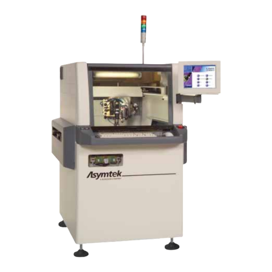
Training Guide Course No. 196514 Information Sheet 1-1-1 System Features System Description X-1000 Series dispensing systems are designed primarily for Surface Mount Application (SMA), Solder Paste (SP), Advanced Semiconductor Package Assembly (ASPA), and Printed Circuit Board Assembly (PCBA) applications. It provides a modular approach to hardware, software and factory integration. Because of the modular design, it can be easily configured for other applications. - Page 27 Training Guide Course No. 196514 Diagram Sheet 1-1-1 X-1000 Series Dispensing System (1) Hatch (8) Light Beacon (2) Safety Interlock Switch (7) Dispensing Head (3) EMO Button (6) Conveyor Area (4) Dispensing Calibration Module (5) Vision System X-1020 Front View (Hood Open) Level 2 Maintenance, X-1000 Series Dispensing Systems P/N 196515 (Revision A)
-
Page 28: Basic Platform
Training Guide Course No. 196514 Information Sheet 1-1-2 System Features (Continued) Basic Platform Model Features X-1010 X-1020 Application Surface Mount Flip Chip Underfill, Dam & Fill, Cavity Fill DV-01 through DV-05 DJ-2000 DV-07 through DV-09 Recommended DV-7000 DJ-2000, DP-3000, DV-7000 Valve Series Dual Valve Combinations (option) Dual Valve Combinations (option) -
Page 29: Lesson
Training Guide Course No. 196514 Lesson 1-2 Safety Warning Labels Introduction It is essential to observe safety precautions when operating and performing maintenance on X-1000 Series Equipment. Equipment areas that require special attention are identified with safety warning labels. All personnel should locate and identify all safety warning labels on the system before use. - Page 30 Training Guide Course No. 196514 Table 1-2-1 Safety Warning Labels Symbol Warning Type Hazard This label warns of a high-voltage component that can cause shock, burn, or death. Use extreme Electrical caution when working in or around these areas. (Shock Hazard) Disconnect and lock out power before servicing.
- Page 31 Training Guide Course No. 196514 Diagram Sheet 1-2-1 Typical Safety Warning Label Locations (Front) Thermal Hazard Warning Labels Electrical Hazard Warning Label Heavy Object Warning Label on side of Computer Level 2 Maintenance, X-1000 Series Dispensing Systems P/N 196515 (Revision A)
- Page 32 Training Guide Course No. 196514 Diagram Sheet 1-2-2 Typical Safety Warning Label Locations (Rear) Electrical Hazard Warning Label Heavy Object Fire Hazard Warning Label Warning Label Thermal Hazard Warning Label Electrical Hazard Warning Label Level 2 Maintenance, X-1000 Series Dispensing Systems P/N 196515 (Revision A)
-
Page 33: Lesson
Training Guide Course No. 196514 Lesson 1-3 Startup/Shutdown Procedures Introduction To ensure safe operation of the X-1000 Dispensing Systems, all personnel working on or around the dispensing systems should be aware of all electrical power and pneumatic distribution sources and follow recommended startup/shutdown procedures. -
Page 34: Main Power Inlet/Circuit Breaker
Training Guide Course No. 196514 Information Sheet 1-3-1 Startup/Shutdown Procedures Main Power Inlet /Circuit Breaker The Main Power Inlet is located on the rear panel and connects to the facility power source through the Main Power cord. To turn the main power ON (l l l l ) and OFF (0), use the Main Circuit Breaker located on the Power Manager at the lower left rear panel of the dispensing system (See Diagram Sheet 1-3-1). -
Page 35: Service Shutdown
Training Guide Course No. 196514 Information Sheet 1-3-2 Startup/Shutdown Procedures (Continued) D. Service Shutdown Wait for the dispensing program to complete. Purge the Dispensing Valve as specified in the applicable Dispensing Valve Installation and Operation Manual. Press the black OFF (0) button on the Operator’s Console and verify that all dispensing system motion stops. -
Page 36: Lock Out/Tag Out Ac Power And Pneumatic Pressure
Training Guide Course No. 196514 Information Sheet 1-3-3 Startup/Shutdown Procedures (Continued) Lock Out/Tag Out AC Power and Pneumatic Pressure Lock out and tag out electrical power and pneumatic pressure when performing service or maintenance work on the dispensing system. Failure to do so could cause serious injury to the user and/or serious damage to the dispensing system. - Page 37 Training Guide Course No. 196514 Diagram Sheet 1-3-1 Main Power Lock Out Circuit Breaker Main Circuit Locking Flange Breaker Level 2 Maintenance, X-1000 Series Dispensing Systems 1-13 P/N 196515 (Revision A)
-
Page 38: Post-Service Startup
Training Guide Course No. 196514 Information Sheet 1-3-4 Startup/Shutdown Procedures (Continued) Post-Service Startup Remove locks and tags on the Main Power Inlet and Main Air Inlet. Reconnect the facility air hose and AC power cable to the dispensing system. Verify that the dispensing system Hatch is closed. Check the EMO Switches on the front and rear of the dispensing system to see if they have been activated. -
Page 39: Lesson
Training Guide Course No. 196514 Lesson 1-4 Emergency Shutdown Procedure Introduction As a safety precaution, all Asymtek dispensing systems are equipped with an Emergency Machine OFF (EMO) Button. The EMO allows you to quickly power down the dispensing system in case of an emergency. Enabling Objective Identify emergency shutdown situations, and test the functionality of the EMO button. -
Page 40: Emo Operation
Training Guide Course No. 196514 Information Sheet 1-4-1 Emergency Shutdown Features Emergency Machine Off (EMO) Buttons There are two EMO buttons on the X-1000 dispensing system. One is located on the front panel of the dispensing system and the other is located on the rear panel of the dispensing system. - Page 41 Training Guide Course No. 196514 Diagram Sheet 1-4-1 Emergency Machine Off (EMO) Locations Front Panel Back Panel Level 2 Maintenance, X-1000 Series Dispensing Systems 1-17 P/N 196515 (Revision A)
-
Page 42: Emo Circuit Diagram
Training Guide Course No. 196514 Diagram Sheet 1-4-2 EMO Circuit Diagram +24V FRONT EMO CIRCUIT, REAR EMO LATCHING, DP, NC (x2) X-1000 VENT AIR SWITCHES SPST-NC (x2) OFF BUTTON MOMENTARY, DP, NC +24V_STOP_A ON BUTTON +24V_START_A MOMENTARY, DP, NO +24V_START_B SELF-LATCHING RELAYS RETURN... -
Page 43: Exercise
Training Guide Course No. 196514 Exercise Sheet 1-4-1 Testing the Functionality of the EMO Button Turn the Main Circuit Breaker ON (I). Make sure the EMO is deactivated by turning the knob counter clockwise until it pops back into position. Press the ON button. - Page 44 Training Guide Course No. 196514 Level 2 Maintenance, X-1000 Series Dispensing Systems 1-20 P/N 196515 (Revision A)
-
Page 45: Lesson
Training Guide Course No. 196514 Lesson 1-5 Safety Interlock and Light Beacon Introduction The Safety Interlock is a safety feature that is activated when the dispenser hood is opened. The Safety Interlock immediately stops all dispensing activity to protect the operator from serious injury. The Light Beacon can serve as a visual or audible warning device, indicating different Interlock status conditions either by turning on a different colored light for each condition, or by issuing an alarm. -
Page 46: Light Beacon
Training Guide Course No. 196514 Information Sheet 1-5-1 Safety Interlock and Light Beacon Light Beacon Located at the top right corner of the system, the Light Beacon is device that displays system status. The Beacon has four different color lights, which can be constantly ON or flashing, and can give an audible alarm. -
Page 47: Light Beacon Color Indications
Training Guide Course No. 196514 Table 1-5-1 Light Beacon Color Indications Beacon Color Dispensing Status Recovery Procedures ALERT All motion, outputs, fluid pump, and motion controls are disabled. One of the following conditions exists: Solid - System in an Emergency Restart machine. - Page 48 Training Guide Course No. 196514 Level 2 Maintenance, X-1000 Series Dispensing Systems 1-24 P/N 196515 (Revision A)
-
Page 49: Lesson
Training Guide Course No. 196514 Lesson 1-6 Facility Requirements Introduction Facility Power Requirements depend upon your dispensing system configuration. Failure to meet these requirements could result in serious bodily injury and damage to the dispensing system. Enabling Objective State facility requirements and facility safety precautions for X-1000 Dispensing Systems. -
Page 50: Facility Safety Precautions
Training Guide Course No. 196514 Information Sheet 1-6-1 Facility Requirements Facility Requirements To ensure optimal performance and safety, it is necessary to install the dispensing system in a facility that meets or exceeds the following requirements. Characteristic Specification Floor Space Required See Diagram Sheet 1-6-1 on page 1-27. - Page 51 Training Guide Course No. 196514 Diagram Sheet 1-6-1 Typical Dimensions for X-1000 Series Dispensing Systems FRONT VIEW SIDE VIEW TOP VIEW UNITS Millimeters [Inches] Level 2 Maintenance, X-1000 Series Dispensing Systems 1-27 P/N 196515 (Revision A)
- Page 52 Training Guide Course No. 196514 Level 2 Maintenance, X-1000 Series Dispensing Systems 1-28 P/N 196515 (Revision A)
-
Page 53: Lesson
Training Guide Course No. 196514 Lesson 1-7 Safety Precautions Introduction It is essential to observe safety precautions when operating and performing maintenance on X-1000 Dispensing Systems. Following safety precautions prevents injury to the operator as well as damage to the equipment. Enabling Objective Identify Safety Precautions and Electrostatic Discharge (ESD) procedures. -
Page 54: Operator Safety Precautions
Training Guide Course No. 196514 Information Sheet 1-7-1 Safety Precautions Operator Safety Precautions Locate and identify safety warning labels on your system before initial use. DO NOT BYPASS THE SAFETY INTERLOCK! In case of a malfunction, immediately push the Emergency Machine Off (EMO) button. -
Page 55: Material Safety Precautions
Training Guide Course No. 196514 Information Sheet 1-7-2 Safety Precautions (Continued) Material Safety Precautions Refer to the Material Safety Data Sheet (MSDS) for health, chemical, safety, and disposal information for all fluids and materials before use. All fluids and materials should be disposed of according to local regulations. Wear gloves to prevent the contact of caustic chemicals with skin. -
Page 56: Additional Precautions For Service Personnel
Training Guide Course No. 196514 Information Sheet 1-7-3 Safety Precautions (Continued) Additional Precautions for Service Personnel Only qualified personnel should be permitted to perform maintenance and troubleshooting procedures. When performing service or maintenance work on the dispensing system in areas marked with an Electrical Warning Label make sure to disconnect all power cords and lock out/tag out equipment as detailed in “Lock Out/Tag Out AC Power and Pneumatic Pressure”... -
Page 57: Module 2 Equipment Operation
Training Guide Course No. 196514 MODULE 2 EQUIPMENT OPERATION Module 2 Equipment Operation Lesson 2-1 Theory of Operation Lesson 2-2 Dispensing System Components Lesson 2-3 Power Distribution Lesson 2-4 Pneumatic Distribution Lesson 2-5 Electrical and Pneumatic Paths Lesson 2-6 Vision System Lesson 2-7 Dispense Valves Lesson 2-8... - Page 59 Training Guide Course No. 196514 Lesson 2-1 Theory of Operation Introduction All X-1000 Series Dispensing Systems work in accordance with the same theory of operation demonstrating the highly developed process control. Model-specific differences may occur depending upon system configuration and options installed.
-
Page 60: System Mechanics
Training Guide Course No. 196514 Information Sheet 2-1-1 Theory of Operation System Mechanics The X-1000 consists of essentially two interdependent machines whose motions are coordinated through a computer interface using Fluidmove for Windows NT (FmNT) software. The first machine is a three-axis robot (Dispense Head) mounted on an overhead gantry. -
Page 61: Conveyor
Training Guide Course No. 196514 Information Sheet 2-1-2 Theory of Operation (Continued) Conveyor The Conveyor is used to move workpieces into and out of the dispensing area. Depending upon application requirements and system configuration, the conveyor setup may vary. There are two models, one for Advanced Semi- Conductor Package Assembly (ASPA) and one for Surface Mount Technology (SMT). -
Page 62: Theory Of Operation
Training Guide Course No. 196514 Information Sheet 2-1-3 Theory of Operation (Continued) Typically, FmNT performs the following functions: Coordinates the motions of the conveyor with upstream machines. Moves the workpiece on the conveyor into the dispense station. Moves the dispense head until the camera finds a fiducial mark on the workpiece. -
Page 63: Operations Flow Chart
Training Guide Course No. 196514 Diagram Sheet 2-1-1 Operations Flow Chart A part enters the system from an upstream location A part sensor detects part and the part is indexed Pre- Dispense Zone? Part is Conveyed to Pre-Dispense Zone Part is Conveyed to Dispense Zone Stop Pins are lowered to stop part transport. - Page 64 Training Guide Course No. 196514 Level 2 Maintenance, X-1000 Series Dispensing Systems P/N 196515 (Revision A)
-
Page 65: Lesson
Training Guide Course No. 196514 Lesson 2-2 Dispensing System Components Introduction The Power Manager supplies and regulates the electrical power for all major system components. When performing maintenance on X-1000 Dispensing Systems, it is essential to understand the functions of the Power Manager as well as the controllers and modules to which it distributes power. -
Page 66: Power Manager
Training Guide Course No. 196514 Information Sheet 2-2-1 Dispensing System Components Power Manager The Power Manager is located in the rear lower cabinet to the far left and houses the main circuit breaker (25 amperes) and the Main Power Inlet. It also contains EMO circuitry, an in-line filter for power going to the Computer and a time delay relay. - Page 67 Training Guide Course No. 196514 Diagram Sheet 2-2-1 Power Manager/Conveyor Controller Power Manager X-1000 Rear View – Door Open Conveyor Controller X-1000 Front View – Door Open Level 2 Maintenance, X-1000 Series Dispensing Systems P/N 196515 (Revision A)
-
Page 68: Dispense Head Controller
Training Guide Course No. 196514 Information Sheet 2-2-2 Dispensing System Components (Continued) Dispense Head Controller The Dispense Head Controller manages dispense head processes and input/output. These include: Valve speed and acceleration control Control of Camera Lighting Control of Height Sensor Control of Needle Heaters Control of Pneumatic solenoids Even though the software can have direct control over conveyor operations,... -
Page 69: Computer
Training Guide Course No. 196514 Information Sheet 2-2-3 Computer Computer The Computer is located on the right hand side of the lower front cabinet. It houses the following electronic components: Main Interface PWA ITI Vision Card ATI Graphics Card PIO96-J Card PMAC Card The Computer is mounted on a bracket that is bolted to the floor of the lower front cabinet. -
Page 70: Ati Graphics Card
Training Guide Course No. 196514 Information Sheet 2-2-4 Computer (Continued) D. ATI Graphics Card The image captured by the ITI Vision card is output to the ATI Graphics card. This card, in turn, outputs the video image to the system Monitor. PIO96-J Card The PIO96-J Card provides Input/Output for signals controlled directly through FmNT. - Page 71 Training Guide Course No. 196514 Diagram Sheet 2-2-2 Main Interface PWA System Computer Main Interface PWA X-1000 Front Cabinet Level 2 Maintenance, X-1000 Series Dispensing Systems 2-13 P/N 196515 (Revision A)
- Page 72 Training Guide Course No. 196514 Level 2 Maintenance, X-1000 Series Dispensing Systems 2-14 P/N 196515 (Revision A)
-
Page 73: Servo Shelf
Training Guide Course No. 196514 Information Sheet 2-2-5 Servo Shelf Servo Shelf The Servo Shelf, located in upper rear of the machine, houses the following components: Servo Power Transformer DC Cooling Fan XY Servo Interface PWA Main Air Solenoid X and Y Servo Amplifiers Dual Action Solenoid Low Pressure Sensor It is accessible via a service hatch. -
Page 74: Dc Cooling Fan
Training Guide Course No. 196514 Information Sheet 2-2-6 Servo Shelf (Continued) Low Pressure Sensor The Low Pressure Sensor is located on the right side of the Servo Shelf. It can be manually set for a pressure from 10 to 100 psi (69 to 689 kPa). The sensor will issue a signal when main air pressure is lower than the manual set point. - Page 75 Training Guide Course No. 196514 Diagram Sheet 2-2-3 XY Servo Interface PWA Servo Shelf Cover Servo Shelf XY Servo Interface PWA (Located on Servo Shelf) Level 2 Maintenance, X-1000 Series Dispensing Systems 2-17 P/N 196515 (Revision A)
-
Page 76: Positional Sensors
Training Guide Course No. 196514 Information Sheet 2-2-7 Positional Sensors Linear Encoders Linear encoders supply positional information to the PMAC by way of the Servo Interface PWA. An encoder is mounted on both the X- and Y-axis, but not the Z-axis. They keep track of the actual position of the Dispensing Head. -
Page 77: Dispense Head
Training Guide Course No. 196514 Information Sheet 2-2-8 Dispense Head Dispense Head Mechanics The X-1000 implements a counter balanced, rack and pinion Dispensing Head that is powered by a servo motor assembly. The motor is located on the Dispense Head and has both Hall and Rotary Encoders. - Page 78 Training Guide Course No. 196514 Level 2 Maintenance, X-1000 Series Dispensing Systems 2-20 P/N 196515 (Revision A)
-
Page 79: Lesson
Training Guide Course No. 196514 Lesson 2-3 Power Distribution Introduction AC power enters the dispensing system from the facility power source at the Main Power Inlet. From there, it runs through the Main Circuit Breaker to the Power Manager. The Power Manager supplies power directly to several system components, which in turn distribute power to other components. - Page 80 Training Guide Course No. 196514 Information Sheet 2-3-1 Power Distribution Power Manager AC power enters the dispensing system from the facility power source at the Main Power Inlet. From there, it runs through the Main Circuit Breaker (25 Amperes) to the Power Manager. The Power Manager distributes power to the following components: Main Interface PWA (12 VDC) Servo Power Transformer (208-240 VAC)
-
Page 81: Computer Power Supply
Training Guide Course No. 196514 Information Sheet 2-3-2 Power Distribution (Continued) D. Computer Power Supply The Computer Power Supply receives power directly from the Power Manager. It distributes power to: Main Interface PWA (+5,-5, 12,-12 VDC) Main CPU Board (5, 12 VDC) PMAC Card (+5, -5,-12,+12 VDC) PIO –... - Page 82 Training Guide Course No. 196514 Diagram Sheet 2-3-1 Power Distribution Main Power Inlet 208/240 VAC Main Circuit Breaker 208/240 VAC Emergency Machine Off Start Button Power Manager (EMO) 240 VAC 24 VDC 220 VAC 208/240 VAC 24 VDC 240 VAC +5,-5,+12, -12 Conveyor Computer 250 Watt...
-
Page 83: Lesson
Training Guide Course No. 196514 Lesson 2-4 Pneumatic Distribution Introduction The X-1000 Dispensing Systems uses compressed air at up to 120 psi of pressure for the conveyor stop pins and board clamp, the vacuum generator, the dispense valve, the syringe cooler and the needle heater. Enabling Objective Understand the X-1000 series pneumatic system and distribution. - Page 84 Training Guide Course No. 196514 Information Sheet 2-4-1 Pneumatic Distribution Main Air Regulator and Gauge Air enters the dispensing system from the facility air source at the Main Air Regulator and Gauge located on the dispensing system back panel. From the Main Air Pressure Regulator, it travels to the Main Air Solenoid and then to the following: Valve Pressure Low Air Sensor...
-
Page 85: Dual Action Solenoid
Training Guide Course No. 196514 Information Sheet 2-4-2 Pneumatic Distribution (Continued) D. Valve Pressure Regulator and Gauge The Valve Pressure Regulator and Gauge is located behind the lower front cabinet door and controls the air pressure that actuates some dispense valves (DJ-2000, DP-3000) during dispensing. -
Page 86: Low Pressure Sensor
Training Guide Course No. 196514 Information Sheet 2-4-3 Pneumatic Distribution (Continued) G. Low Pressure Sensor Located in the middle of the shelf to the far right, the sensor can be manually adjusted between 10-100 psi. The sensor will go low when the main air pressure is lower than the manual set point. - Page 87 Training Guide Course No. 196514 Diagram Sheet 2-4-1 Air Gauges and Regulators Valve 1 Fluid Air Pressure Valve 2 Fluid Regulator Air Pressure Regulator Tooling Air Pressure Regulator Valve 1 Fluid Air Digital Gauge Valve Air Pressure Gauge Valve 2 Fluid Air Tooling Air Digital Gauge Impingement...
- Page 88 Training Guide Course No. 196514 Table 2-4-1 Recommended Air Pressure Settings and Flowrates Device Pressure/Flowrate Comments Main Air Pressure Regulator 551 kPa (80 psi) Facility pressure is 586 to 620 kPa (85 to 90 psi) Fluid Air Pressure Regulator 206 to 275 kPa (30 to 40 psi) Depends on fluid being dispensed and Dispensing Valve being used.
- Page 89 Training Guide Course No. 196514 Diagram Sheet 2-4-2 Pneumatic Distribution Main Air Regulator Assembly Main Air Solenoid Dual Action Valve Low Air Sensor Fluid Pressure V1 and V2 Valve Pressure Solenoid Valve Lift Tables or Manifold Clamp Bars Tooling Pressure Stop Pins Impingement Flowmeters...
-
Page 90: Adjusting The Main Air Pressure Regulator
Training Guide Course No. 196514 Exercise Sheet 2-4-1 Adjusting the Main Air Pressure Regulator Verify that the facility air supply is connected to the Main Air Inlet. At the top of the Filter-Regulator, locate the regulator adjustment knob. Gently pull up on the adjustment knob to unlock it. While watching the gauge, rotate the adjustment knob: Clockwise to increase pressure up to the desired level. - Page 91 Training Guide Course No. 196514 Diagram Sheet 2-4-3 Main Air Pressure Regulator and Gauge Main Air Pressure Gauge Regulator Adjustment Knob – – Filter Regulator Main Air Inlet Water Trap Facility Air Supply Line Water Drain Level 2 Maintenance, X-1000 Series Dispensing Systems 2-33 P/N 196515 (Revision A)
- Page 92 Training Guide Course No. 196514 Exercise Sheet 2-4-2 Adjusting the Valve and Tooling Air Pressure Regulators Verify that the dispensing system is ON. The Light Beacon will display a green or solid yellow light. Open the lower front cabinet door and find the appropriate pressure regulator. Gently pull the regulator adjustment knob downward to unlock.
-
Page 93: Adjusting Impingement Flowmeters
Training Guide Course No. 196514 Exercise Sheet 2-4-3 Adjusting the Fluid Air Pressure Regulators and Impingement Flowmeters Adjusting the Fluid Air Pressure Regulators: Verify that the dispensing system is ON. The Light Beacon will display a green or solid yellow light. Open the lower front cabinet door and find the Fluid Air Pressure Regulator to (See Diagram Sheet 2-4-1 on page 2-29). - Page 94 Training Guide Course No. 196514 Exercise Sheet 2-4-4 Fluid Air Pressure Gauge Configuration Make sure the air pressure to the Valve 1 Fluid Air Pressure Gauge is OFF by turning the Valve 1 Fluid Air Pressure Regulator knob to the right (counterclockwise) until it stops.
-
Page 95: Digital Pressure Gauge Configuration
Training Guide Course No. 196514 Diagram Sheet 2-4-4 Digital Pressure Gauge LED Display 123.4 Indicators OUT 1 OUT 2 Up Button Down Button Set Button Level 2 Maintenance, X-1000 Series Dispensing Systems 2-37 P/N 196515 (Revision A) - Page 96 Training Guide Course No. 196514 Level 2 Maintenance, X-1000 Series Dispensing Systems 2-38 P/N 196515 (Revision A)
-
Page 97: Lesson
Training Guide Course No. 196514 Lesson 2-5 Electrical and Pneumatic Paths Introduction Understanding how the dispense head and conveyor is commanded to move is essential for troubleshooting problems. Each movement follows a precise electrical and pneumatic path and each component performs a specific function in the dispensing process. -
Page 98: Dispensing Head Moves In X Or Y-Axis
Training Guide Course No. 196514 Diagram Sheet 2-5-1 Dispensing Head Moves in X or Y-Axis Computer FmNT A program command is issued to the FmNT software. PMAC Card Receives FmNT command to move Dispensing Head to a specific XY position. Sends low-voltage direction and power level output signals to the X and Y Servo Amplifiers. -
Page 99: Dispensing Head Moves In Z-Axis
Training Guide Course No. 196514 Diagram Sheet 2-5-2 Dispensing Head Moves in Z-Axis Computer FmNT Command A program command is issued to the FmNT software. PMAC Card Receives FmNT command to move Dispensing Head to a specific Z-axis position. Sends low-voltage direction and power level output signals to the Z Servo Amplifier. -
Page 100: Dispensing Head Finds Home
Training Guide Course No. 196514 Diagram Sheet 2-5-3 Dispensing Head Finds Home Computer FmNT Command A program command is issued to the FmNT software. PMAC Card Receives FmNT command to move Dispense Head to specific position. Sends low-voltage direction and power level output signals to the XYZ Servo Amplifiers. -
Page 101: Dispensing Head Performs A Height Sense
Training Guide Course No. 196514 Diagram Sheet 2-5-4 Dispensing Head Performs a Height Sense FmNT Command PIO96 Card PMAC Card Main Interface PWA Main Interface PWA XY Servo Interface PWA X-Y Servo Interface PWA Dispense Head Controller Z Servo Interface PWA Z-Axis Servo Motor Lowers Height Sensor Armed Dispensing Head... -
Page 102: Conveyor Belt Moves
Training Guide Course No. 196514 Diagram Sheet 2-5-5 Conveyor Belt Moves FmNT Command A program command is issued to the FmNT software. Controller Area Network (CAN) Communications network between Computer (FmNT) and Conveyor Controller Module Conveyor/Heater Controller Conveyor Interface PWA Performs conveyor logical functions such as belt movement (direction, duration and speed), width adjustment,... - Page 103 Training Guide Course No. 196514 Diagram Sheet 2-5-6 Operation of Stop Pin and Lift Tables/Clamp Bars Board Sensor Detects presence of workpieces in pre- dispense, dispense, and post- dispense stations. Signals are routed to Conveyor/Heater Controller via Conveyor Interconnect PWA. Conveyor Interconnect PWA Passively routes signals between Conveyor Controller and Pneumatic...
- Page 104 Training Guide Course No. 196514 Level 2 Maintenance, X-1000 Series Dispensing Systems 2-46 P/N 196515 (Revision A)
-
Page 105: Lesson
Training Guide Course No. 196514 Lesson 2-6 Vision System Introduction The Vision System for the Axiom X-1000 Dispensing System features an ITI Pattern Recognition System with variable red/blue LED lighting. Before adjusting or performing maintenance on the vision system, the technician should be familiar with the vision system components and understand the theory of operation. -
Page 106: Vision System Description
Training Guide Course No. 196514 Information Sheet 2-6-1 Vision System Vision System Description Camera The Vision System uses a miniature, high resolution, black and white machine vision camera to view the work surfaces. Attached to the camera is a vibration-resistant lens system consisting of an aperture, a lens, and a tube. - Page 107 Training Guide Course No. 196514 Diagram Sheet 2-6-1 X-1000 Vision System Camera with Lens Flat Screen Monitor Lighting Module Video Card Image Capture Card Computer Level 2 Maintenance, X-1000 Series Dispensing Systems 2-49 P/N 196515 (Revision A)
-
Page 108: Focusing The Camera
Training Guide Course No. 196514 Exercise Sheet 2-6-1 Focusing the Camera Tools and Materials Needed: 5-mm hex key 4-mm hex key Sample workpiece The camera can be focused using both a coarse adjustment and a fine adjustment depending on the extent of focusing necessary. Usually, only the fine adjustment is required. - Page 109 Training Guide Course No. 196514 Diagram Sheet 2-6-2 Camera Focus Adjustment Fine Focus Adjustment Screw Vertical Camera Bracket Camera Course Focus Adjustment Screws Lens Level 2 Maintenance, X-1000 Series Dispensing Systems 2-51 P/N 196515 (Revision A)
-
Page 110: Calibrating The Camera
Training Guide Course No. 196514 Exercise Sheet 2-6-2 Calibrating the Camera In FmNT Main Window, click on Configuration. Select Setup Vision from the Configuration menu. (See Diagram Sheet 2-6-3 The Dialog Window for the Vision System opens on page 2-53). In the Dialog Window, click on the Calibrate button. - Page 111 Training Guide Course No. 196514 Diagram Sheet 2-6-3 Vision Setup Dialog Boxes Level 2 Maintenance, X-1000 Series Dispensing Systems 2-53 P/N 196515 (Revision A)
- Page 112 Training Guide Course No. 196514 Level 2 Maintenance, X-1000 Series Dispensing Systems 2-54 P/N 196515 (Revision A)
-
Page 113: Lesson
Training Guide Course No. 196514 Lesson 2-7 Dispense Valves Introduction There are various pumps and valves available for the X-1000 Dispensing Systems. Pump/Valve selection is generally based on the viscosity of the fluid as well as the dispensing program goals. Enabling Objective Describe the dispense valve theory of operation and make valve adjustments as necessary. -
Page 114: Dp-3000
Training Guide Course No. 196514 Information Sheet 2-7-1 DP-3000 Description The DP-3000 is a piston pump or positive displacement pump dispenses fluid by displacing a volume of fluid in a closed system chamber. An electric motor turns two gears, which drive a lead screw attached to a piston into the chamber. - Page 115 Training Guide Course No. 196514 Diagram Sheet 2-7-1 DP-3000 Pneumatic and Electrical Connections – DP-3000 Level 2 Maintenance, X-1000 Series Dispensing Systems 2-57 P/N 196515 (Revision A)
-
Page 116: Dv-7000
Training Guide Course No. 196514 Information Sheet 2-7-2 DV-7000 Description The DV-7000 is a rotary positive displacement auger valve. Auger valves use a combination of air pressure on the fluid column and an electric motor driven auger or screw to move the fluid through the needle or dispense tip onto the part. - Page 117 Training Guide Course No. 196514 Diagram Sheet 2-7-2 DV-7000 Pneumatic and Electrical Connections – DV-7000 Level 2 Maintenance, X-1000 Series Dispensing Systems 2-59 P/N 196515 (Revision A)
-
Page 118: Dj-2000
Training Guide Course No. 196514 Information Sheet 2-7-3 DJ-2000 Description The DJ-2000 Dispense Jet is a high throughput air-actuated dispensing jet. These devices are referred to as “jets”, because they use an air-activated needle to force a jet of fluid from the fluid chamber. The DJ-2000 employs a non-contact dispensing method in which individual drops of material are formed and shot from the nozzle to the substrate. - Page 119 Training Guide Course No. 196514 Diagram Sheet 2-7-3 DJ-2000 Pneumatic and Electrical Connections – DJ2100 Level 2 Maintenance, X-1000 Series Dispensing Systems 2-61 P/N 196515 (Revision A)
- Page 120 Training Guide Course No. 196514 Level 2 Maintenance, X-1000 Series Dispensing Systems 2-62 P/N 196515 (Revision A)
-
Page 121: Lesson
Training Guide Course No. 196514 Lesson 2-8 Conveyor Operations Introduction The Conveyor is used to move parts into and out of the dispensing area. All X- 1000 Dispensing Systems are equipped with a Surface Mount Equipment Manufacturers Association (SMEMA) compatible belt conveyor. Enabling Objective Understand the conveyor theory of operation and setup and level the conveyor. - Page 122 Training Guide Course No. 196514 Information Sheet 2-8-1 Conveyor Operations Conveyor Configuration Conveyor configuration varies depending upon the application requirements and the type of heaters installed. Typically, the X-1010 uses an o-ring conveyor and the X-1020 uses a belt conveyor. Standard features include: Motorized rail width adjustment Pre-queue/dispense/post-queue stations...
- Page 123 Training Guide Course No. 196514 Information Sheet 2-8-2 Conveyor Operations (Continued) Stop Pins/Clamp Bars Stop pins and clamp bars are used to index parts in the dispensing area and hold them in place during dispensing procedures. Optical sensors determine the board’s presence and mechanical pins stop the board in the correct position.
- Page 124 Training Guide Course No. 196514 Information Sheet 2-8-3 Conveyor Operation (Continued) The workpiece is conveyed into the Pre-dispense Station. A Stop Pin is engaged to stop workpiece transport. A Board Sensor detects the workpiece. The Lift Table rises to hold the workpiece in place. Pre-dispense Station Heater Tooling, set at a programmed temperature, heats the workpiece.
- Page 125 Training Guide Course No. 196514 Information Sheet 2-8-4 Conveyor Operations (Continued) Fluid is dispensed. The fluid is dispensed onto the workpiece according to a pre-programmed dispensing pattern. Refer to the FmNT User Guide for programming details. The workpiece leaves the Dispense Station. When dispensing is complete, the Stop Pin is disengaged, the Lift Table lowers, and the workpiece is conveyed to the Post-Dispense Station or out of the dispensing system.
-
Page 126: Conveyor Configuration
Training Guide Course No. 196514 Exercise Sheet 2-8-1 Conveyor Configuration Select Setup Conveyors from the Configuration menu. The Setup Conveyors dialog box opens. Click on the arrow next to the Type box and select the type of conveyor installed on your system. If you are using a non-Asymtek conveyor, select Custom. - Page 127 Training Guide Course No. 196514 Diagram Sheet 2-8-1 FmNT Conveyor Setup and Configuration Dialog Boxes Level 2 Maintenance, X-1000 Series Dispensing Systems 2-69 P/N 196515 (Revision A)
-
Page 128: Checking Adjustable Width Conveyor Clearance
Training Guide Course No. 196514 Exercise Sheet 2-8-2 Checking Adjustable-Width Conveyor Clearance Perform this procedure only if your dispensing system has been configured for an application that requires an adjustable conveyor width. DO NOT perform the procedure for fixed-width conveyor configurations Verify that electrical cables and pneumatic lines near the conveyor are not in danger of being pinched or snagged during conveyor operation. -
Page 129: Checking Fixed Width Conveyor Clearance
Training Guide Course No. 196514 Exercise Sheet 2-8-3 Checking Fixed-Width Conveyor Clearance Perform the following procedure only if your dispensing system has been configured for an application that requires a fixed conveyor width. DO NOT perform the procedure for adjustable-width conveyor configurations Verify that electrical cables and pneumatic lines near the conveyor are not in danger of being pinched or snagged during conveyor operation. -
Page 130: Leveling The Conveyor
Training Guide Course No. 196514 Exercise Sheet 2-8-4 Leveling the Conveyor In the FmNT Main Window, click on the Configuration button and select Setup Height Sensor. (See Diagram In the Height Sensor Configuration dialog box, click on CAN-HS Sheet 2-11-1 on page 2-95). In the second Height Sensor Configuration dialog box, click on the ARM/DISARM button. - Page 131 Training Guide Course No. 196514 Diagram Sheet 2-8-2 Conveyor Rail Level Measurement Locations Item Description Approximate Measurement Location (Order Shown: A, B, C, etc.) Rear Conveyor Rail Stop Pin Front Conveyor Rail Part Sensor Level 2 Maintenance, X-1000 Series Dispensing Systems 2-73 P/N 196515 (Revision A)
-
Page 132: Rough Adjusting The Conveyor Rail Width
Training Guide Course No. 196514 Exercise Sheet 2-8-5 Rough Adjusting the Conveyor Rail Width When the rails are determined to be level with dispensing system mechanics, obtain a sample workpiece identical to the one that will be used during production. Narrow or widen the spacing between the Conveyor Rails to fit the sample workpiece as follows: In the Jog Commands dialog box, click on... -
Page 133: Checking Upstream/Downstream Smema Communication
Training Guide Course No. 196514 Exercise Sheet 2-8-6 Checking Upstream/Downstream SMEMA Communication Attach the TS-01 upstream and downstream cable adapters to the TS-01 box. Attach the TS-01 upstream and downstream cables to the appropriate SMEMA connectors at the rear of the dispensing system. Make sure that all of the I O/INDEP switches along the edge of the TS-01 ↔... - Page 134 Training Guide Course No. 196514 Diagram Sheet 2-8-3 TS-01 SMEMA Simulator Computer Network Cable Upstream SMEMA Port TS-01 Test Box Downstream SMEMA Port TS-01 Cables Level 2 Maintenance, X-1000 Series Dispensing Systems 2-76 P/N 196515 (Revision A)
-
Page 135: Checking Overall Conveyor Component Operations
Training Guide Course No. 196514 Exercise Sheet 2-8-7 Checking Overall Conveyor Component Operations Place one sample workpiece in the pre-dispense station such that it does not trigger the part sensor. Close the dispensing system hatch. In the FmNT Main Window, click on Teach a Program In the Programming Window, click on the icon... - Page 136 Training Guide Course No. 196514 Level 2 Maintenance, X-1000 Series Dispensing Systems 2-78 P/N 196515 (Revision A)
-
Page 137: Lesson
Training Guide Course No. 196514 Lesson 2-9 Dispensing Calibration Module Introduction The Dispensing Calibration Module consists of the Weigh Station, Purge Station, Needle Sensor, Tactile Sensor and Ceramic Tile. The stainless steel housing protects the components from fluid spills and work area mishaps. Occasionally, the Dispensing Calibration Module may need to be leveled. -
Page 138: Dispensing Calibration Module Components
Training Guide Course No. 196514 Information Sheet 2-9-1 Dispensing Calibration Module Dispensing Calibration Module Components The Dispensing Calibration Module consists of the following components: Weigh Station - The weigh station contains a scale that measures the weight of dispensed fluid. - It sends the information to the FmNT software for mass flow calibration. -
Page 139: Dispensing Calibration Module Leveling And Height Adjustment
Training Guide Course No. 196514 Exercise Sheet 2-9-1 Dispensing Calibration Module Leveling and Height Adjustment The dispensing system and scale must be level before performing this procedure. Put a production sample workpiece at the upstream mouth of the conveyor. In the Main Window, click on Teach a Program In the Programming Window, click on the Load a Board icon The workpiece will be conveyed to the dispense area and the lift... - Page 140 Training Guide Course No. 196514 Exercise Sheet 2-9-2 Dispensing Calibration Module Leveling and Height Adjustment (Continued) Move the camera over the purge station lid. The video image should be clear and focused. If the image is not focused, repeat Steps 8 and 9. If the image is focused and the bubble in the level is in the center of the circle, go to Step 10.
- Page 141 Training Guide Course No. 196514 Diagram Sheet 2-9-1 Dispensing Calibration Module Leveling Recessed Fine Adjustment Screws Course Adjustment Screws (Pitch) Recessed Fine Adjustment Screws Course Adjustment Screws (Yaw) Bubble Level Ceramic Tile Substrate Level 2 Maintenance, X-1000 Series Dispensing Systems 2-83 P/N 196515 (Revision A)
- Page 142 Training Guide Course No. 196514 Level 2 Maintenance, X-1000 Series Dispensing Systems 2-84 P/N 196515 (Revision A)
-
Page 143: Lesson 2-10 Linear Encoders
Training Guide Course No. 196514 Lesson 2-10 Linear Encoders Introduction Linear encoders are mounted on each axis and keep track of the actual dispensing head position. If the dispensing head starts and then stops or loses its position, it may be necessary to adjust the encoders. Enabling Objective 2.10 Perform the procedure to adjust the Linear Encoders. -
Page 144: Linear Encoder Calibration
Training Guide Course No. 196514 Information Sheet 2-10-1 Linear Encoders Linear Encoders A Linear Encoder is a sensor that is mounted on each of the X and Y-axes on the dispensing head. They keep track of the actual dispensing head position. This information is supplied on a constant basis to the PMAC by way of the Servo Interconnect PCA. - Page 145 Training Guide Course No. 196514 Diagram Sheet 2-10-1 X and Y-Axis Linear Encoder Locations X-Axis Scanner X-Axis Scale Y-Axis Scale Y-Axis Scanner Gapping Tool Level 2 Maintenance, X-1000 Series Dispensing Systems 2-87 P/N 196515 (Revision A)
-
Page 146: Linear Encoder Gap Adjustment
Training Guide Course No. 196514 Exercise Sheet 2-10-1 Linear Encoder Gap Adjustment Tools and Materials Needed: 0.9-mm encoder gapping tool (P/N 194983) 3-mm hex key Loctite thread locker 242 Open the dispensing system hatch. Make sure the yellow beacon light is displayed and all system motion has stopped before reaching into the dispensing area. - Page 147 Training Guide Course No. 196514 Exercise Sheet 2-10-2 Adjusting the Encoder Scanner to Encoder Scale Gap If it is not already open, open the dispensing system Hatch. Make sure the yellow beacon light is displayed and all system motion has stopped before reaching into the dispensing area. If the Heaters are still hot, use extreme caution when performing this operation.
- Page 148 Training Guide Course No. 196514 Level 2 Maintenance, X-1000 Series Dispensing Systems 2-90 P/N 196515 (Revision A)
-
Page 149: Lesson 2-11 Height Sensor
Training Guide Course No. 196514 Lesson 2-11 Height Sensor Introduction All X-1000 Dispensing Systems are equipped with a height sensor to ensure that the dispensing system maintains a constant dispensing height during production runs. As part of routine maintenance, it may be necessary to test the sensor and adjust the probe. - Page 150 Training Guide Course No. 196514 Information Sheet 2-11-1 Height Sensor Height Sensor The height sensor checks and gauges substrate height to help maintain a consistent dispensing gap. It uses a stainless steel probe to contact the dispensing surface. When the dispensing head lowers and the probe tip contacts the substrate, it triggers an I/O in the Height Sensor.
-
Page 151: Probe Adjustments
Training Guide Course No. 196514 Information Sheet 2-11-2 Height Sensor (Continued) D. Probe Adjustments Depending on the dispensing pattern, the substrate material, and/or the needle size, you may need to adjust the probe height in relation to the needle height, the distance between the probe tip and the needle tip. These adjustments can improve the throughput and dispensing quality. -
Page 152: Configuring The Height Sensor
Training Guide Course No. 196514 Exercise Sheet 2-11-1 Configuring the Height Sensor In the Main Window, click on Configuration. Select Setup Height Sensor from the Configuration Menu. The Height Sensor Configuration box opens Click on the down arrow under Height Sensor Type and select RT from the drop down menu. - Page 153 Training Guide Course No. 196514 Diagram Sheet 2-11-1 Height Sensor Configuration Level 2 Maintenance, X-1000 Series Dispensing Systems 2-95 P/N 196515 (Revision A)
-
Page 154: Centering The Micrometer Locking Screw
Training Guide Course No. 196514 Exercise Sheet 2-11-2 Centering the Micrometer Locking Screw Before making any probe adjustments, the micrometer locking screw should be in a neutral position that will allow maximum upward or downward adjustment. Perform this procedure only if the micrometer locking screw is not centered in the slot. - Page 155 Training Guide Course No. 196514 Diagram Sheet 2-11-2 Micrometer Locking Screw Micrometer Micrometer Locking Screw Slot in Bracket Level 2 Maintenance, X-1000 Series Dispensing Systems 2-97 P/N 196515 (Revision A)
-
Page 156: Probe Removal And Replacement
Training Guide Course No. 196514 Exercise Sheet 2-11-3 Probe Removal and Replacement To remove and replace the Height Sensor probe: Verify the following: The probe is in the down position. The Dispensing Head is at the top of its Z-Axis travel. The Dispensing Head is at the front of the dispensing chamber. - Page 157 Training Guide Course No. 196514 Diagram Sheet 2-11-3 Height Sensor Probe Installation Probe Bushing Probe Setscrew Access Hole Probe Probe Block Level 2 Maintenance, X-1000 Series Dispensing Systems 2-99 P/N 196515 (Revision A)
-
Page 158: Minor Probe Height Adjustments
Training Guide Course No. 196514 Exercise Sheet 2-11-4 Minor Probe Height Adjustments To make minor adjustments to the probe height: Verify the following: The probe is in the down position. The Dispensing Head is at the top of its Z-axis travel and at the front of the dispensing chamber. - Page 159 Training Guide Course No. 196514 Diagram Sheet 2-11-4 Height Sensor Adjustment Probe Height Micrometer Micrometer Locking screw Mounting Bracket Probe Sleeve (with setscrew) Power Cable Solenoid Probe Probe Travel Locking Screw LED Indicators Probe Travel Probe Setscrew Adjustment Screw Access Hole Level 2 Maintenance, X-1000 Series Dispensing Systems 2-101 P/N 196515 (Revision A)
-
Page 160: Major Probe Height Adjustments
Training Guide Course No. 196514 Exercise Sheet 2-11-5 Major Probe Adjustments This procedure can be used to adjust both the height of the Height Sensor probe and the distance the probe is from the dispensing needle. To make major adjustments to the probe height: Verify the following: The probe is in the down position. - Page 161 Training Guide Course No. 196514 Diagram Sheet 2-11-5 Probe-to-Needle Alignment Height Sensor Needle Probe 1 mm (0.04 in.) 1.78–2.54 mm (0.07–010 in. Probe-to-Needle Alignment Level 2 Maintenance, X-1000 Series Dispensing Systems 2-103 P/N 196515 (Revision A)
-
Page 162: Probe Travel Adjustment
Training Guide Course No. 196514 Exercise Sheet 2-11-6 Probe Travel Adjustment The optimal probe travel varies with the configuration of the workpiece and the presence of obstacles in the dispensing area. The probe must retract enough to avoid contacting the workpiece and colliding with dispensing chamber obstacles such as Board Sensors and Stop Pins. - Page 163 Training Guide Course No. 196514 Diagram Sheet 2-11-6 Probe Travel Adjustment Probe Travel Locking Screw Probe Travel Adjustment Screw Level 2 Maintenance, X-1000 Series Dispensing Systems 2-105 P/N 196515 (Revision A)
- Page 164 Training Guide Course No. 196514 Level 2 Maintenance, X-1000 Series Dispensing Systems 2-106 P/N 196515 (Revision A)
-
Page 165: Lesson 2-12 Needle Sensor
Training Guide Course No. 196514 Lesson 2-12 Needle Sensor Introduction The needle sensor locates the XYZ position of the needle. It is also used to determine the XYZ location of the Height Sensor Probe in relation to the needle. These locations are sent to the dispensing software, which uses them during the programming process and during production runs. -
Page 166: Needle Sensor Maintenance
Training Guide Course No. 196514 Information Sheet 2-12-1 Needle Sensor Needle Sensor The needle sensor automatically compensates for XYZ changes in needle position due to a needle change or bent needle so that you can change needles and continue production without reprogramming the system. It does not compensate for XYZ location changes in parts, substrates, tooling or fixtures. - Page 167 Training Guide Course No. 196514 Diagram Sheet 2-12-1 Needle Sensor Dispensing Head Tactile Needle Conveyor Sensor Fiber-optic Needle Sensor Level 2 Maintenance, X-1000 Series Dispensing Systems 2-109 P/N 196515 (Revision A)
-
Page 168: Needle Sensor Configuration
Training Guide Course No. 196514 Exercise Sheet 2-12-1 Needle Sensor Configuration To configure the Needle Sensor: In the FmNT Main Window, click on Configuration. Select Machine Offsets from the Configuration Menu. Select Machine Offsets Parameters from the cascading menu. In the Machine Offsets Parameters dialog box, make sure that your Needle (See Diagram Sheet 2-12-2 Sensor type appears in the Sensor Type text box on page 2-111). - Page 169 Training Guide Course No. 196514 Diagram Sheet 2-12-2 Needle Sensor Configuration Level 2 Maintenance, X-1000 Series Dispensing Systems 2-111 P/N 196515 (Revision A)
-
Page 170: Functional Testing Of Needle Sensor
Training Guide Course No. 196514 Exercise Sheet 2-12-2 Functional Testing of Needle Sensor Verify your dispensing system has been configured for the type of Needle Sensor installed as follows: In the FmNT main Window, click on Configuration . Select Machine Offsets from the Configuration menu. In the dropdown menu, select Machine Offsets Parameters . -
Page 171: Lesson 2-13 Needle Heater
Training Guide Course No. 196514 Lesson 2-13 Needle Heater Introduction The Needle Heater is used to heat fluid at the needle tip, which eliminates the stringing effect sometimes found with adhesives and epoxies. It also keeps fluid viscosity constant and ensures consistent fluid flow. Enabling Objective 2.13 Install and adjust a needle heater. -
Page 172: Needle Heater
Training Guide Course No. 196514 Information Sheet 2-13-1 Needle Heaters Needle Heater The needle heater works with both the Asymtek DV and DP Series Dispensing Valves. The needle heater warms the fluid at the needle tip which eliminates the stringing effect sometimes found with adhesives and epoxies, keeps fluid viscosity constant, and ensures consistent fluid flow. - Page 173 Training Guide Course No. 196514 Diagram Sheet 2-13-1 Needle Heater Needle Heater Power Connection Heating Element Power Cable Heating Element Thumbscrew Level 2 Maintenance, X-1000 Series Dispensing Systems 2-115 P/N 196515 (Revision A)
-
Page 174: Installing A Needle Heater
Training Guide Course No. 196514 Exercise Sheet 2-13-1 Installing a Needle Heater Verify that the Dispensing Head is at the top of its Z-axis travel and at the front of the dispensing chamber. If not in position, use the Position Controls to move the Dispensing Head as specified in the Operation section of this manual. - Page 175 Training Guide Course No. 196514 Diagram Sheet 2-13-2 Needle Heater Installation Needle Heater Heating Element Needle Heater Power Connector Level 2 Maintenance, X-1000 Series Dispensing Systems 2-117 P/N 196515 (Revision A)
-
Page 176: Adjusting Needle Heater Settings
Training Guide Course No. 196514 Exercise Sheet 2-13-2 Adjusting Needle Heater Settings If not already ON, start up the dispensing system by pressing ON (I) on the Operator’s Console. In the FmNT Main Window, click on Run a Program. In the Production Window, click on Setup and in the text box select Setup Heate In the Heater Control Window (Figure 12 4), locate the loop (channel) for the Needle Heater installed on your system. - Page 177 Training Guide Course No. 196514 Diagram Sheet 2-13-3 FmNT Heater Control Window Level 2 Maintenance, X-1000 Series Dispensing Systems 2-119 P/N 196515 (Revision A)
- Page 178 Training Guide Course No. 196514 Level 2 Maintenance, X-1000 Series Dispensing Systems 2-120 P/N 196515 (Revision A)
-
Page 179: Lesson 2-14 Part Heaters
Training Guide Course No. 196514 Lesson 2-14 Part Heaters Introduction Some X-1000 Dispensing Systems are equipped with underboard substrate heating systems. There are two types of heaters currently available on the X- 1000 systems: contact heaters and impingement heaters. Both types of heaters are capable of independent temperature regulation in pre-heat, dispense heat and post-heat zones. -
Page 180: Contact Heaters
Training Guide Course No. 196514 Information Sheet 2-14-1 Part Heaters Theory of Operation There are two types of part heaters used on the X-1000 Dispensing Systems. Both types work in accordance with the same theory of operation. Contact Heaters Impingement Heaters Heaters can be arranged in any of the three zones along the Conveyor: Pre-Heat Zone (Pre-Dispense Station) Dispense Heat Zone (Dispense Station) - Page 181 Training Guide Course No. 196514 Diagram Sheet 2-14-1 Contact Heaters Contact Heater (Installed) Power Cord Lift Table Heater Top Plate Vacuum Hose Vacuum Port FmNT Temperature Settings Conveyor/ RTD Readouts Contact Heater Heater Controller Modules Regulated Power Vacuum Air Pneumatic Vacuum Solenoid Valves Generators...
-
Page 182: Impingement Heaters
Training Guide Course No. 196514 Information Sheet 2-14-2 Part Heaters (Continued) Impingement Heaters Impingement heaters are similar to Contact heaters except that they blow hot air up at the part rather than use a vacuum to hold the part in place. The determining factor when choosing between Contact and Impingement heat is the part carrier being used for the application Heater Operation:... - Page 183 Training Guide Course No. 196514 Diagram Sheet 2-14-2 Impingement Heaters Impingement Heater Power Cord (Installed) Lift Table Heater Top Plate Impingement Air Vent Impingement Air Hose FmNT Temperature Settings RTD Readouts Impingement Conveyor/ Heater Modules Heater Controller Regulated Power Impingement Air Main Air Manual Impingement...
-
Page 184: Electrically Testing Part Heaters And Needle Heaters
Training Guide Course No. 196514 Exercise Sheet 2-14-1 Electrically Testing Part Heaters and Needle Heaters In the FmNT Main Window, click on Tools. In the Tools Window, click on Terminal. Click on Heaters. In the Heater Control Window, locate the loops (channels) for the Heater Tooling installed on your system (See Diagram Sheet 2-14-3 on page 2-127). - Page 185 Training Guide Course No. 196514 Diagram Sheet 2-14-3 Heater Control Window Temperature Set Point Column Present Channel (Loop) Temperature Name Column Message Value Column Column Heater On/Off Column Level 2 Maintenance, X-1000 Series Dispensing Systems 2-127 P/N 196515 (Revision A)
-
Page 186: Temperature Testing Part Heaters And Needle Heaters
Training Guide Course No. 196514 Exercise Sheet 2-14-2 Temperature Testing Part Heaters and Needle Heaters Check all air and electrical connections to the Heaters. In the Heater Control Window, locate the loops (channels) for the Heaters installed on your system and verify the messages for all the Heaters read OK (See Diagram Sheet 2-14-3 on page 2-127). -
Page 187: Checking Contact Heater Vacuums
Training Guide Course No. 196514 Exercise Sheet 2-14-3 Checking Contact Heater Vacuums This procedure assumes the following: Sample workpieces are on the Conveyor in the pre-dispense, dispense, and post-dispense stations as applicable to your system configuration. The dispensing system Hatch is open Monitor displays Station I/O Diagnostic tab of MPC555 I/O Diagnostic dialog box. -
Page 188: Impingement Heater Airflow Adjustment
Training Guide Course No. 196514 Exercise Sheet 2-14-4 Impingement Heater Airflow Adjustment Airflow to an impingement heater is adjusted by turning the knob on its flowmeter located behind the lower front cabinet door. Flow is read on the gauge on the front of the flowmeter. -
Page 189: Checking The Function Of Impingement Air Valve And Flowmeters
Training Guide Course No. 196514 Exercise Sheet 2-14-5 Checking the Function of Impingement Air Valve and Flowmeters Locate the Impingement Air Valve and Flowmeters in the Front Cabinet of the dispensing system. Open the Impingement Air Valve by turning the handle counterclockwise such that it is parallel with the airline. -
Page 190: Heater Calibration
Training Guide Course No. 196514 Exercise Sheet 2-14-6 Heater Calibration Tools and Materials Needed: Calibrated Temperature Measuring Device In the FmNT Main Window, click on Tools. In the Tools Window, click on Terminal. Click on Heaters. In the Heater Control Window, locate the loops (channels) for the part heaters installed on your system. - Page 191 Training Guide Course No. 196514 Exercise Sheet 2-14-7 Heater Calibration (Continued) Measure and record the actual temperature of each heater using a calibrated temperature probe as follows: For part heaters, take readings on the top surfaces at both ends and the middle of each part heater.
- Page 192 Training Guide Course No. 196514 Level 2 Maintenance, X-1000 Series Dispensing Systems 2-134 P/N 196515 (Revision A)
-
Page 193: Lesson 2-15 Board Sensors
Training Guide Course No. 196514 Lesson 2-15 Board Sensors Introduction Board sensors are sensors located along the length of the conveyor rail that detect the presence of a board or part. Board sensors should be adjusted after initial installation and when the sensors are failing to sense the presence of a board. -
Page 194: Downward Facing Sensors
Training Guide Course No. 196514 Information Sheet 2-15-1 Board Sensors Board Sensors Board sensors are optic sensors located along the length of the conveyor rails. They detect the presence of a board or part and report the detection to the Conveyor Controller. -
Page 195: Testing The Board Sensors
Training Guide Course No. 196514 Exercise Sheet 2-15-1 Testing the Board Sensors This procedure assumes the following: Each conveyor station has a part sensor that is positioned to sense the workpiece. The rail width has been adjusted to fit a production sample workpiece. FmNT is in the MPC555 I/O Diagnostic dialog box. -
Page 196: Adjusting The Upward-Facing Board Sensors
Training Guide Course No. 196514 Exercise Sheet 2-15-2 Adjusting the Upward-facing Board Sensors (X-1010 only) Tools and Materials Needed: Flathead Screwdriver Production Sample Workpiece Locate the Board Sensor under the front Conveyor Rail and find the Adjustment (See Diagram Sheet 2-15-1 on page 2- Screw and red LED on the rear of the Sensor 139). - Page 197 Training Guide Course No. 196514 Diagram Sheet 2-15-1 Upward Facing Board Sensor Adjustment Conveyor Belt (on Front Conveyor Rail) Lift Red LED Table Level 2 Maintenance, X-1000 Series Dispensing Systems 2-139 P/N 196515 (Revision A)
- Page 198 Training Guide Course No. 196514 Exercise Sheet 2-15-3 Adjusting the Upward-facing Board Sensors (Continued) Manually move the board back and forth on the Conveyor Belt over the Board Sensor to verify the sensitivity adjustment. The red LED should come ON (or the “Board Present” bit should say ON), when the sample board is moved over the Board Sensor.
- Page 199 Training Guide Course No. 196514 Exercise Sheet 2-15-4 Adjusting the Downward-facing Board Sensors (X-1020 only) Tools and Materials Needed: Flathead screwdriver Phillipshead screwdriver Sample workpiece identical to one used during production run Using a Phillipshead screwdriver, remove the screws holding down the dispensing area front plate.
- Page 200 Training Guide Course No. 196514 Exercise Sheet 2-15-5 Adjusting the Downward-facing Board Sensors (Continued) Slide the mode selection switch to Run. The Amplifier will display the incident light level. Slide the switch to Mode. Dial the thumbwheel until the flashing cursor is next to Output 2 and then push down on the thumbwheel.
-
Page 201: Adjusting The Downward-Facing Board Sensors
Training Guide Course No. 196514 Diagram Sheet 2-15-2 Adjusting the Downward Facing Board Sensors Rear Conveyor Rail Dispensing Calibration Module Dispensing Area Front Cover Board Sensor Fiber Optic Amplifier LED Display Output Switch Thumbwheel Mode Selection Switch Level 2 Maintenance, X-1000 Series Dispensing Systems 2-143 P/N 196515 (Revision A) - Page 202 Training Guide Course No. 196514 Level 2 Maintenance, X-1000 Series Dispensing Systems 2-144 P/N 196515 (Revision A)
-
Page 203: Lesson 2-16 Stop Pins/Lift Tables/Clamp Bars
Training Guide Course No. 196514 Lesson 2-16 Stop Pins/Lift Tables/Clamp Bars Introduction When a part is conveyed into the system, a sensor detects its presence and indexes the part. Stop pins are raised to stop the board transport. Clamp bars or lift tables raise to hold the part in place. -
Page 204: Stop Pins
Training Guide Course No. 196514 Information Sheet 2-16-1 Stop Pins/Lift Tables/Clamp Bars Stop Pins Stop pins are pneumatic devices used to stop parts at each station. The stop pins should raise and lower smoothly and quickly. Lift Tables/Clamp Bars The lift tables or clamp bars rise to hold the part in place when it is being dispensed upon. -
Page 205: Checking Stop Pin, Lift Table And Clamp Bar Operation
Training Guide Course No. 196514 Exercise Sheet 2-16-1 Checking Stop Pin, Lift Table and Clamp Bar Operation Checking Stop Pin Operation: This procedure assumes that the dispensing system Hatch is open and FmNT is on the Station I/O Diagnostic tab of the MPC555 I/O Diagnostic dialog box. In the Station I/O Diagnostic dialog box, locate the Stop Pin output buttons (See Diagram Sheet 2-8-1 on page 2-69). -
Page 206: Leveling The Lift Tables
Training Guide Course No. 196514 Exercise Sheet 2-16-2 Leveling the Lift Tables This procedure assumes that each Lift Table is equipped with Heater Tooling and that the Height Sensor has been functionally tested. In the FmNT Main Window, click on the Configuration button and select Setup Height Sensor . - Page 207 Training Guide Course No. 196514 Diagram Sheet 2-16-1 Lift Table Measurement Locations Measurement Locations Level 2 Maintenance, X-1000 Series Dispensing Systems 2-149 P/N 196515 (Revision A)
- Page 208 Training Guide Course No. 196514 Exercise Sheet 2-16-3 Adjusting the Lift Table/Clamp Bar Airflow Open the dispensing system Hatch. Do not reach into the dispensing chamber until yellow beacon light is displayed and all system motion has stopped. If the Heaters are hot, use extreme caution when performing this operation.
- Page 209 Training Guide Course No. 196514 Diagram Sheet 2-16-2 Pneumatic Controls Rear Conveyor Rail Pneumatic Supply Heat Tooling Air and Lines Electric Supply Bulkhead Lift Table Pneumatic Controls Flow Control Valves (Front Rail) Clamp Bar (Rear Rail) Front Conveyor Rail Clamp Bar Pneumatic Cylinder Level 2 Maintenance, X-1000 Series Dispensing Systems...
- Page 210 Training Guide Course No. 196514 Diagram Sheet 2-16-3 Removing the Dispensing Area Front Cover Dispensing Area Front Cover Quick Release Fastener (6 total) Front Cover Bracket Front Conveyor Rail Level 2 Maintenance, X-1000 Series Dispensing Systems 2-152 P/N 196515 (Revision A)
-
Page 211: Lesson
Training Guide Course No. 196514 Lesson 2-17 PMAC Introduction The PMAC Card (Programmable Multi Axis Controller) connects to the X, Y, and Z Servo Amplifiers and provides positional information to the robot. PMAC is a computer, capable of standalone operation with its own stored programs. PMAC Commands are used on X-1000 Series dispensing system to control the dispensing head. -
Page 212: Pmac Initialization Files
Training Guide Course No. 196514 Information Sheet 2-17-1 PMAC PMAC Initialization Files There are several FmNT files that contain configuration variables for the PMAC. These files are downloaded to the PMAC upon FmNT startup and include the following: PMACINI.PMC - This file contains several servo parameters and PMAC configuration variables. -
Page 213: Pmac Watchdog
Training Guide Course No. 196514 Information Sheet 2-17-2 PMAC (Continued) PMAC Watchdog The PMAC motion control board has an on-board “watchdog timer” circuit whose job it is to detect a number of conditions that could result in a dangerous malfunction of the equipment. It provides a fail-safe shutdown to guard against Software or hardware malfunction - The timer must see a square wave input of a frequency greater than... -
Page 214: Pmac Commands
Training Guide Course No. 196514 Information Sheet 2-17-3 PMAC Terminal Commands PMAC Commands Saving Downloads In the terminal Mode type: Save [enter] Clearing Memory In the Terminal Mode type: $$$*** [enter] Home Commands Enables amplifiers M214-[enter] Closes the servos, powers the motors a [enter] Homes the Z axis b105r [enter]... - Page 215 Training Guide Course No. 196514 Information Sheet 2-17-4 PMAC Terminal Commands (Continued) Running XY Motion Programs M900=x [enter] Where x is in terms of micrometers M901=y [enter] Where y is in terms of micrometers b100r [enter] b-buffer, r-run Aborting a Program a [enter] How to abort a program Stopping a Program / Opening a Servo Loop...
- Page 216 Training Guide Course No. 196514 Level 2 Maintenance, X-1000 Series Dispensing Systems 2-158 P/N 196515 (Revision A)
-
Page 217: Lesson 2-18 Pmac Plot
Training Guide Course No. 196514 Lesson 2-18 PMAC Plot Introduction One of the diagnostic tools available is a built-in tool called PMAC Plot. PMAC Plot is used to measure and gather position, velocity and acceleration profiles of the dispense head for dispensing programs written in FmNT that are installed on Asymtek servo systems. - Page 218 Training Guide Course No. 196514 Information Sheet 2-18-1 PMAC Plot PMAC Plot PMAC Plot is a program that plots the electrical signals of the dispense head path on the screen. The information can be saved and printed. This program is generally used by Service Technicians as a diagnostic tool to measure and gather position, velocity and acceleration profiles.
-
Page 219: Gathering Data
Training Guide Course No. 196514 Diagram Sheet 2-18-1 Gathering Data Process FmNT Programming Window Level 2 Maintenance, X-1000 Series Dispensing Systems 2-161 P/N 196515 (Revision A) - Page 220 Training Guide Course No. 196514 Information Sheet 2-18-2 PMAC Plot (Continued) Plotting Data Open the PMAC Plot Program. Press [Ctrl]-ESC Select Programs, Pmac Plot, PmacPlot. Click on the Quick Plot tab. Click on Motors to Gather. Select motors (commanded and actual) to be analyzed. 1 = x-motor, 2 = y-motor, 3 = z-motor.
-
Page 221: Plotting Data
Training Guide Course No. 196514 Diagram Sheet 2-18-2 Plotting Data Motors to Gather Clears Gather buffer Choices Level 2 Maintenance, X-1000 Series Dispensing Systems 2-163 P/N 196515 (Revision A) -
Page 222: Analyzing Data
Training Guide Course No. 196514 Information Sheet 2-18-3 PMAC Plot (Continued) D. Analyzing Data For every acceleration move, there is an equal and opposite deceleration peak for each move. Both acceleration and deceleration peaks will match in magnitude. It’s possible to have a negative peak acceleration and positive peak deceleration if the move is going backwards. - Page 223 Training Guide Course No. 196514 Diagram Sheet 2-18-3 Analyzing and Printing Data Acceleration Move in X 5 counts equal 1 (Mtr #1) mil or 25 um (since 5um/count encoders) Deceleration 20 ms after deceleration Move. Stops X. peak is when following error is measured.
- Page 224 Training Guide Course No. 196514 Level 2 Maintenance, X-1000 Series Dispensing Systems 2-166 P/N 196515 (Revision A)
-
Page 225: Module 3 Routine Maintenance
Training Guide Course No. 196514 MODULE 3 ROUTINE MAINTENANCE Module 3 Routine Maintenance Lesson 3-1 Routine Maintenance Procedures Lesson 3-2 Purge Boot and Weigh Station Maintenance Lesson 3-3 Scale Leveling and Calibration Lesson 3-4 Draining the Water Trap Lesson 3-5 Lubricating the X-Beam and Y-Rail Linear Bearings Lesson 3-6 Lubricating and Tensioning the Positioner Cables... -
Page 227: Lesson
Training Guide Course No. 196514 Lesson 3-1 Routine Maintenance Procedures Introduction Performing routine maintenance is necessary to prevent part degradation and to ensure high quality dispensing performance. There are several procedures that should be performed on a regular basis to optimize system performance. Enabling Objective Identify recommended routine maintenance procedures and their recommended frequency. -
Page 228: Routine Maintenance Procedure Schedule
Training Guide Course No. 196514 Information Sheet 3-1-1 Routine Maintenance Procedure Schedule Maintenance Recommended Est. Instructions Procedure Frequency Time Remove the Purge Station cover. Clean the boot and cover with a small Clean Purge Daily 3 minutes bottlebrush and the solvent recommended by Station boot. - Page 229 Training Guide Course No. 196514 Information Sheet 3-1-2 Routine Maintenance Procedure Schedule (Continued) Maintenance Recommended Est. Instructions Procedure Frequency Time Lubricate the X- and Y-Axis Monthly See Exercise Sheet 3-5-1 on page 3-24. minutes bearings. Use a clean, soft cloth to wipe any dust off of the sensors.
- Page 230 Training Guide Course No. 196514 Level 2 Maintenance, X-1000 Series Dispensing Systems P/N 196515 (Revision A)
-
Page 231: Lesson
Training Guide Course No. 196514 Lesson 3-2 Purge Boot and Weigh Station Maintenance Introduction The plastic cups in the Purge Boot and Weigh Station should be replaced on a daily basis. In addition the purge boot must be cleaned and the banjo wiper replaced. -
Page 232: Replacing Purge/Weigh Station Cups, Banjo Wipe And Cleaning The Purge Boot
Training Guide Course No. 196514 Exercise Sheet 3-2-1 Replacing Purge/Weigh Station Cups, Banjo Wipe and Cleaning Purge Boot If a dispensing program is running, click on Pause in the FmNT Run Window. The dispensing system will complete the current workpiece and then pause. With no dispense program running, open the dispensing system Hatch. - Page 233 Training Guide Course No. 196514 Diagram Sheet 3-2-1 Replacing the Purge and Weigh Station Cups and Banjo Wipe Banjo Wipe Purge Boot/ Cover Purge Station Cup Weigh Station Cup Level 2 Maintenance, X-1000 Series Dispensing Systems P/N 196515 (Revision A)
-
Page 234: Replacing The Purge Boot
Training Guide Course No. 196514 Exercise Sheet 3-2-2 Replacing the Purge Boot If a dispensing program is running, click on Pause in the FmNT Run Window. The dispensing system will complete the current workpiece and then pause. With no dispense program running, open the dispensing system Hatch. Remove the Purge Station Cover as shown in Diagram Sheet 3-2-1 on page 3-7. - Page 235 Training Guide Course No. 196514 Diagram Sheet 3-2-2 Replacing the Purge Boot Purge Boot Purge Station Level 2 Maintenance, X-1000 Series Dispensing Systems P/N 196515 (Revision A)
- Page 236 Training Guide Course No. 196514 Level 2 Maintenance, X-1000 Series Dispensing Systems 3-10 P/N 196515 (Revision A)
-
Page 237: Lesson
Training Guide Course No. 196514 Lesson 3-3 Scale Leveling and Calibration Introduction Some X-1000 Dispensing Systems include a digital scale capable of recording the weight of dispensed fluid. The scale must be leveled and calibrated in order to record an accurate weight. Enabling Objective Perform the procedure to level and calibrate the scale. -
Page 238: Digital Scale
Training Guide Course No. 196514 Information Sheet 3-3-1 Scale Leveling and Calibration Digital Scale The weigh station is a small reservoir containing a metal pedestal resting on an electronic balance. It contains a plastic disposable cup with a removable lid. The scale is located under the Dispenser Service Area weigh station. -
Page 239: Leveling The Scale
Training Guide Course No. 196514 Exercise Sheet 3-3-1 Leveling the Scale Tools and Materials Needed: 1.5-mm hex key Isopropyl alcohol 2.5-mm hex key Circular level 4-mm hex key Clean, lint-free cloth 9/64-inch hex key Lab gloves Short flat blade screwdriver Tweezers Set of standard weights Note: Standard weights must be in good condition and have recent certification... - Page 240 Training Guide Course No. 196514 Exercise Sheet 3-3-2 Leveling the Scale (Continued) To level the scale: Remove the Dispensing Area Front Cover and put it in a safe place. Lay the plate down on a flat surface. Do not stand it on edge or lean it against something as this may bend the plate.
- Page 241 Training Guide Course No. 196514 Diagram Sheet 3-3-1 Leveling the Scale Circular Level Scale Pedestal Balance Mechanism Scale Leveling Screws Quick Release Dispensing Area Fasterners Front Cover (6 total) Front Conveyor Rail Front Cover Bracket Front Plate Removal Level 2 Maintenance, X-1000 Series Dispensing Systems 3-15 P/N 196515 (Revision A)
-
Page 242: Calibrating The Scale
Training Guide Course No. 196514 Exercise Sheet 3-3-3 Calibrating the Scale Both the dispensing system and the scale must be leveled prior to performing the following procedure. Remove the Weigh Station Cover, banjo wiper, and cup from inside of the Weigh Station. - Page 243 Training Guide Course No. 196514 Diagram Sheet 3-3-2 Scale Setup Dialog Box Level 2 Maintenance, X-1000 Series Dispensing Systems 3-17 P/N 196515 (Revision A)
- Page 244 Training Guide Course No. 196514 Level 2 Maintenance, X-1000 Series Dispensing Systems 3-18 P/N 196515 (Revision A)
-
Page 245: Lesson
Training Guide Course No. 196514 Lesson 3-4 Draining the Water Trap A. Introduction Because the facility air supply may contain moisture that can damage the dispensing system, the X-1000 is equipped with a water trap that condenses this moisture. The water trap condenses this moisture before it enters the dispenser pneumatic system. -
Page 246: Draining The Water Trap
Training Guide Course No. 196514 Exercise Sheet 3-4-1 Draining the Water Trap Tools and Materials Needed: Container for waste water Perform a Service Shutdown as described in Information Sheet 1-3-2 on page 1-11. Locate the water trap at the rear of the system. Hold a container under the water trap to catch the water. - Page 247 Training Guide Course No. 196514 Diagram Sheet 3-4-1 Water Trap Regulator Water Trap Bowl Guard (bowl inside) Main Air Inlet Drain Valve Level 2 Maintenance, X-1000 Series Dispensing Systems 3-21 P/N 196515 (Revision A)
- Page 248 Training Guide Course No. 196514 Level 2 Maintenance, X-1000 Series Dispensing Systems 3-22 P/N 196515 (Revision A)
-
Page 249: Lesson
Training Guide Course No. 196514 Lesson 3-5 Lubricating the X-Beam and Y-Rail Linear Bearings Introduction The X, Y, and Z-axes support the dispense head and allow it to travel within the dispensing area. The dispense head is the portion of the machine that moves during dispensing operation. -
Page 250: Lubricating The X-Beam And Y-Rail Linear Bearings
Training Guide Course No. 196514 Exercise Sheet 3-5-1 Lubricating the X-Beam and Y-Rail Linear Bearings Tools and Materials Needed: Grease Gun Isopropyl alcohol Linear bearing grease (NSK-PS2)* Soft cloth Rubber Gloves Personal Protective Equipment Make sure that the dispensing system is turned OFF before attempting this procedure or serious injury may occur. - Page 251 Training Guide Course No. 196514 Diagram Sheet 3-5-1 Lubricating the X-Beam and Y-Rail Linear Bearings Linear Bearing Car (1 of 8) X-Beam Y-Rail Grease Fitting (one at end of each car) Level 2 Maintenance, X-1000 Series Dispensing Systems 3-25 P/N 196515 (Revision A)
- Page 252 Training Guide Course No. 196514 Level 2 Maintenance, X-1000 Series Dispensing Systems 3-26 P/N 196515 (Revision A)
-
Page 253: Lesson
Training Guide Course No. 196514 Lesson 3-6 Lubricating and Tensioning the Positioner Cables Introduction Proper cable tension is essential for accurate dispensing. Three tensioners maintain proper tension on the X, Y, and Y-idle cables. The X and Y cable tensioners are located near the left front pulley and the Y-idle cable tensioner is located near the right front pulley. -
Page 254: Lubricating The Positioner Cables
Training Guide Course No. 196514 Exercise Sheet 3-6-1 Lubricating the Positioner Cables Verify that the Main Power Circuit Breaker is locked out and the facility air supply is disconnected from the Main Air Inlet before attempting this procedure or serious injury may occur. Use Personal Protective Equipment when working with cleaning and lubrication materials. - Page 255 Training Guide Course No. 196514 Diagram Sheet 3-6-1 Accessing the Positioner Cables Side Panels Safety Covers Servo Shelf Cover Electrical Cable Cover Motor Cover Motor Pulley Mechancal Cables Access Panel Level 2 Maintenance, X-1000 Series Dispensing Systems 3-29 P/N 196515 (Revision A)
-
Page 256: Tensioning The Positioner Cables
Training Guide Course No. 196514 Exercise Sheet 3-6-2 Tensioning the Positioner Cables Use only Asymtek tensioning tool (P/N 805478) for adjusting mechanical cable tension. Use of any other tool or a non-calibrated tool can result in inaccurate dispensing performance or damage to the dispensing system. Tools and Materials Needed: •... - Page 257 Training Guide Course No. 196514 Diagram Sheet 3-6-2 Tensioning the Positioner Cables Y-axis Cable X-axis Cable Tensione Tensioner (left side) (left side) Y-idle Cable Tensioner (right Side) Cable Tensioner Locations Calibrated Tensioning Tool Mechanical Cable Cable Tensioner Level 2 Maintenance, X-1000 Series Dispensing Systems 3-31 P/N 196515 (Revision A)
- Page 258 Training Guide Course No. 196514 Level 2 Maintenance, X-1000 Series Dispensing Systems 3-32 P/N 196515 (Revision A)
-
Page 259: Lesson
Training Guide Course No. 196514 Lesson 3-7 Cleaning and Replacing Conveyor Belts Introduction Checking the condition of the conveyor belts should be a part of the routine maintenance schedule of the dispensing system. Enabling Objective Perform the procedure to clean and replace the conveyor belts. Topic Outline Introduction Overview... -
Page 260: Conveyor Belt Maintenance
Training Guide Course No. 196514 Information Sheet 3-7-1 Cleaning and Replacing Conveyor Belts Conveyor Belt Maintenance To maintain optimum system performance, it is recommended that you change the conveyor belts every six months. Belts may need to be changed more frequently or less frequently, depending upon the volume of part handling. -
Page 261: Removing The Conveyor Belts
Training Guide Course No. 196514 Exercise Sheet 3-7-1 Removing the Conveyor Belts This procedure should only be performed by a trained service technician. Only one Belt should be removed at a time. Use the other Belt as a reference for proper orientation of the Belt being replaced. For ease of reinstallation, you should note the locations and orientations of rail-mounted components before removing them. -
Page 262: Installing A Conveyor Belt
Training Guide Course No. 196514 Exercise Sheet 3-7-2 Installing a Conveyor Belt This procedure should only be performed by a trained service technician. Tools and Materials Needed: 4-mm Hex Key Soft Cloth and Cotton Swabs • • 2.5-mm Hex Key Two P/N 01-0306-00 Conveyor O-rings •... - Page 263 Training Guide Course No. 196514 Diagram Sheet 3-7-1 Conveyor Belt Removal/Installation O-Ring Conveyor Belt Stop Pin Rear Conveyor Rail Pulley Tire Belt Drive Pulley Level 2 Maintenance, X-1000 Series Dispensing Systems 3-37 P/N 196515 (Revision A)
- Page 264 Training Guide Course No. 196514 Level 2 Maintenance, X-1000 Series Dispensing Systems 3-38 P/N 196515 (Revision A)
-
Page 265: Lesson
Training Guide Course No. 196514 Lesson 3-8 Dispense Pump/Valve Maintenance Introduction Performing the recommended maintenance procedures at regular intervals is an essential factor in maintaining maximum performance from the valve. Cleaning involves the removal and disassembly of the dispensing cartridge, and the removal and replacement of several disposable parts. -
Page 266: Dp-3000
Training Guide Course No. 196514 Information Sheet 3-8-1 Valve/Pump Maintenance DP-3000 Maintenance Recommended Frequency Instructions Procedure Before the expiration of the pot life of the fluid. Clean pumping See Exercise Sheet 3-8-2 Immediately when changing chamber Page 3-44 from one type of fluid to another. -
Page 267: Dj-2000
Training Guide Course No. 196514 Information Sheet 3-8-2 Valve/Pump Maintenance (Continued) DJ-2000 Maintenance Recommended Frequency Instruction Procedure Change of Syringe See DJ-2000 Installation Quick Purge and Operations Manual Each dispensing session DJ-2000 Installation Cleaned or disassemble Priming pump See DJ-2000 Installation and Operations Manual Dots are inconsistent or pump is unable to dispense... -
Page 268: Disconnecting The Dp-3000
Training Guide Course No. 196514 Exercise Sheet 3-8-1 Disconnecting the DP-3000 Tools Needed: 5/64-inch hex key Disconnect the DP-3000 black pneumatic hose from the manifold. Disconnect the DP-3000 blue pneumatic hose from the manifold. Disconnect the syringe receiver head hose from the manifold. Disconnect the DP-3000 power cable from the dispense head. - Page 269 Training Guide Course No. 196514 Diagram Sheet 3-8-1 DP 3000 Power Cable Indicators Black P R IM F U L L Pneumatic L IM IT S T O P C O C K Hose 1 /1 Stopcock 3 /4 Cylinder 1 /2 1 /4 Syringe Clip...
-
Page 270: Cleaning The Dp-3000
Training Guide Course No. 196514 Exercise Sheet 3-8-2 Cleaning the DP-3000 Tools and Materials Needed: Soft cloth Scribe Cleaning step bottle brush (provided with DP-3000) Mild solvent or isopropyl alcohol (IPA). Compatible solvent for your fluid (see the MSDS for fluid compatibility) Wipe off the piston with a soft cloth and mild solvent or IPA. - Page 271 Training Guide Course No. 196514 Diagram Sheet 3-8-2 DP-3000 Chamber Assembly Black O-Ring Urethane O-Ring Metal Luer Prime Port Priming Chamber Pumping Chamber Seal (insert ring-side down) Pumping Chamber High Pressure Chamber Assembly Priming O-Ring Plastic Prime Port Priming Chamber Pumping Chamber Seal (insert ring- Static O-Ring...
-
Page 272: Reconnecting The Dp-3000
Training Guide Course No. 196514 Exercise Sheet 3-8-3 Reconnecting the DP-3000 Open the swinging bracket by pressing up on the red swinging bracket latch and gently pulling out on the swinging bracket. Flip the yellow stopcock lever forward to release the stopcock. Flip the green chamber retention lever up 90°. - Page 273 Training Guide Course No. 196514 Diagram Sheet 3-8-3 Closing the DP-3000 Green Chamber Stopcock Retention Lever Actuator Mating Point of Stopcock and Pumping Chamber Blue Detent Lever Level 2 Maintenance, X-1000 Series Dispensing Systems 3-47 P/N 196515 (Revision A)
-
Page 274: Disconnecting The Dv-7000
Training Guide Course No. 196514 Exercise Sheet 3-8-4 Disconnecting the DV-7000 Tools and Materials Needed: 3/8-inch wrench 3/10-inch wrench Small bottle brush Use the Position Controls, either on the front panel or in the Jog Controls in FmNT, and move the dispensing head to the front and center of the dispensing area. - Page 275 Training Guide Course No. 196514 Diagram Sheet 3-8-4 DV-7000 Syringe Air Hose Receiver Head F L O W H E L I - Syringe Syringe Bulkhead Fitting D V - 7 0 Cartridge Release Feed Tube Lever Barbed Cartridge Fitting Level 2 Maintenance, X-1000 Series Dispensing Systems 3-49 P/N 196515 (Revision A)
-
Page 276: Cleaning The Dv-7000
Training Guide Course No. 196514 Exercise Sheet 3-8-5 Cleaning the DV-7000 Tools and Materials Needed: Cleaning solution (MSDS recommended) Cotton swabs Reamer Use MSDS recommended cleaning solution and a small bottle brush or cotton swab to thoroughly clean the feed screw, the upper bearing, the seal, the needle cap, and the inside of the dispensing cartridge. - Page 277 Training Guide Course No. 196514 Diagram Sheet 3-8-5 DV-7000 Dispensing Cartridge Feed Screw Lower Bearing Dispensing Cartridge Seal Level 2 Maintenance, X-1000 Series Dispensing Systems 3-51 P/N 196515 (Revision A)
-
Page 278: Reassembling And Reconnecting The Dv-7000
Training Guide Course No. 196514 Exercise Sheet 3-8-6 Reassembling and Reconnecting the DV-7000 Tools and Materials Needed: 3/10inch wrench 4mm hex key 2mm hex key Phillipshead screwdriver 3mm hex key Inspect the seal and the lower bearing for wear. If they are worn, replace them. Insert the seal spring-side down into the top of the dispensing cartridge. - Page 279 Training Guide Course No. 196514 Diagram Sheet 3-8-6 DV-7000 with Height Sensor e n s h t S H e ig t il e T a c ri e s -S e Level 2 Maintenance, X-1000 Series Dispensing Systems 3-53 P/N 196515 (Revision A)
-
Page 280: Disconnecting The Dj-2000
Training Guide Course No. 196514 Exercise Sheet 3-8-7 Disconnecting the DJ-2000 Tools and Materials Needed: Spanner Wrench Torque Wrench Disconnect the solenoid cable on the DJ-2000 from the dispense head. Disconnect the pneumatic hoses (jet pressure and fluid pressure) from the dispensing head manifold. - Page 281 Training Guide Course No. 196514 Diagram Sheet 3-8-7 DJ-2000 Black Pneumatic Hose Micrometer Assembly Outer Micrometer Collar Micrometer Lock Nut Height Sensor Solenoid Preload Connector Preload Screw Bracket Upper Body Syringe Luer Lock RTD Cable Heater Heater Extension Cable Nozzle Purge Screw Lower...
-
Page 282: Cleaning The Dj-2000
Training Guide Course No. 196514 Exercise Sheet 3-8-8 Cleaning the DJ-2000 Tools and Materials Needed: Solvent .050-inch hex key Ultrasonic Cleaner 7/64-inch hex key Kimwipes Small spanner wrench Cotton swaps (mid-size and mini) Slotted screwdriver Spray Solvent O-ring removal tool Magnifying Glass Pin vise Flashlight... - Page 283 Training Guide Course No. 196514 Diagram Sheet 3-8-8 DJ-2000 – Disassembly for Cleaning Micrometer Micrometer Assembly Lock Nut Preload Screw Dispense Cap Preload Lock Solenoid Valve Upper Body Syringe Luer Lock Purge Screw Needle U-Cup Seal Lower Body Fillister Screw Black (Kalraz) O-Ring Extension...
- Page 284 Training Guide Course No. 196514 Exercise Sheet 3-8-9 Cleaning the DJ-2000 (Continued) If adhesive appears on the needle within 0.25 mm (0.1in.) of the upper body, place the O-ring removal tool in the center of the U-cup seal, and lift it out. Inspect the needle for excessive wear.
-
Page 285: Reassembling The Dj-2000
Training Guide Course No. 196514 Exercise Sheet 3-8-10 Reassembling the DJ-2000 Tools and Materials Needed: Ring and seal insertion tool .050-inch hex key 7/64-inch hex key Spanner Wrench Conductive Grease Kimwipes If you removed the U-cup seal, place it into the bottom side of the lower body, spring side outwards. -
Page 286: Reconnecting The Dj-2000
Training Guide Course No. 196514 Exercise Sheet 3-8-11 Reconnecting the DJ-2000 Tools Needed: 3mm hex key Place the bracket mount into the slot of the Z-head. The top of the bracket mount should be approximately 2” down from the top of the Z-head slot. -
Page 287: Module 4 Troubleshooting
Training Guide Course No. 196514 MODULE 4 TROUBLESHOOTING Module 4 Troubleshooting Lesson 4-1 Obtaining Asymtek Technical Support Lesson 4-2 Power Failure Lesson 4-3 Testing the I/O Functions of the Dispenser and Conveyor Lesson 4-4 Troubleshooting XY-Axis Motion Lesson 4-5 Troubleshooting Z-Axis Motion Lesson 4-6 Troubleshooting the Servo Controller (PMAC) Lesson 4-7... -
Page 289: Lesson
Training Guide Course No. 196514 Lesson 4-1 Obtaining Asymtek Technical Support Introduction Although this course will help you identify and correct many problems you may encounter with your dispensing system, there may be times when it is necessary to contact Asymtek Technical Support. Enabling Objectives Identify the procedure for describing machine faults and contacting Asymtek Technical Support. -
Page 290: Describing Machine Faults
Training Guide Course No. 196514 Information Sheet 4-1-1 Contacting Asymtek Technical Support Describing Machine Faults Summarize the problem, and describe when it started. Write down all of the details of the symptom, remembering how the correct operation should be. Tell what you believe is causing the problem, and how you isolated it to this problem. - Page 291 Training Guide Course No. 196514 Diagram Sheet 4-1-1 Request for Technical Support Request for Technical Support Section 1 COMPANY INFORMATION Section 2 EQUIPMENT INFORMATION Date: Originator: Model: (required): Company Software: Firmware: Ship To Addr1: Voltage Requirements: Ship To Addr2: Light Camera: Source: City:...
- Page 292 Training Guide Course No. 196514 Diagram Sheet 4-1-2 Return Material Authorization (RMA) Form Return Material Authorization Date: RMA Type Legend RMA Type: Originated By: RW = Warranty Replace Part Ship To: RN = Non-warranty Replace Part Customer: FW = Warranty Repair Address: Address: FN = Non-Warranty Repair...
-
Page 293: Lesson
Training Guide Course No. 196514 Lesson 4-2 Power Failure Introduction Power failure can be contributed to a variety of causes. The following section identifies steps to take if you experience a power failure. Enabling Objectives Identify possible causes and solutions to system power failure. Topic Outline Introduction Overview... -
Page 294: System Power Fault Isolation Procedure
Training Guide Course No. 196514 Information Sheet 4-2-1 Power Failure Main Power Fault Isolation Procedure The Main Power Fault Isolation Procedure consists of the following: (Page 4-8) Main Power Verification Failure to provide the required facility electrical power, pneumatic power, and environmental conditions may cause damage to the system and may void the warranty of the system or replacement parts. -
Page 295: Power Troubleshooting Summary
Training Guide Course No. 196514 Information Sheet 4-2-2 Power Failure (Continued) D. Power Troubleshooting Summary Symptom Possible Cause Recovery The Start button has not been Press ON (l) on the Operator’s pressed. Console. Main Power Cable is Check that the Main Power Cable is disconnected. - Page 296 Training Guide Course No. 196514 Diagram Sheet 4-2-1 Main Power Fault Isolation Procedure – Main Power Verification Verify Main Circuit Breaker Verify Main Circuit Breaker on the Power Manager is on the Power Manager is Confirm the Computer Power Confirm the Computer Power ON (I) ON (I) Switch is in the ON (I) position.
- Page 297 Training Guide Course No. 196514 Diagram Sheet 4-2-2 Main Power Fault Isolation Procedure – Main Power Verification (Continued) Verify the DC Power Cable (P/N Verify the DC Power Cable (P/N 193326) is securely connected 193326) is securely connected Locate the power LEDs on the Locate the power LEDs on the between the Computer Interface between the Computer Interface...
- Page 298 Training Guide Course No. 196514 Diagram Sheet 4-2-3 Main Power Fault Isolation Procedure – Main Power Verification (Continued) Are the green Are the green Switch the Main Circuit Breaker Switch the Main Circuit Breaker Switch the Main Circuit Breaker A+15V, and A+5V A+15V, and A+5V to the OFF (0) position.
- Page 299 Training Guide Course No. 196514 Diagram Sheet 4-2-4 Main Power Fault Isolation Procedure – Main Power Verification (Continued) Switch the Main Circuit Breaker Switch the Main Circuit Breaker to the OFF (0) position. to the OFF (0) position. Reconnect the Servo Reconnect the Servo Interconnect A Cable (P/N 06- Interconnect A Cable (P/N 06-...
- Page 300 Training Guide Course No. 196514 Diagram Sheet 4-2-5 System Power Fault Isolation Procedure - System Power Verification Press the green ON (I) button on the Operator's Console. Does the green Does the green Locate the power LEDs on ON (I) button stay ON (I) button stay the XY Servo Interface PWA.
- Page 301 Training Guide Course No. 196514 Diagram Sheet 4-2-6 System Power Fault Isolation Procedure - System Power Verification (Continued) Are the cables Are the cables Switch the Main Circuit Breaker connected to the connected to the Power Manager as Power Manager as to the OFF (0) position.
- Page 302 Training Guide Course No. 196514 Diagram Sheet 4-2-7 System Power Fault Isolation Procedure - Power Cable Verification Switch the Main Circuit Breaker to the OFF (0) position. Disconnect Cable (P/N 06- 4515-00) from the Power Check continuity of pins specified below at Power Manager Power Check continuity of pins specified below at Power Manager Power Control outlet of the Power Control connector J5.
- Page 303 Training Guide Course No. 196514 Diagram Sheet 4-2-8 System Power Fault Isolation Procedure - Front EMO Button Verification Reconnect Cable (P/N 06- 4515-00) to Power Control outlet on Power Manager. Verify the Front EMO Cable is connected to Front EMO Button.
- Page 304 Training Guide Course No. 196514 Diagram Sheet 4-2-9 System Power Fault Isolation Procedure - Rear EMO Button Verification Reconnect Cable (P/N 06- 4515-00) to Power Control outlet on Power Manager. Correct the wiring of the Rear Is the wiring as Is the wiring as EMO Button by changing Verify the Rear EMO Cable is...
- Page 305 Training Guide Course No. 196514 Diagram Sheet 4-2-10 System Power Fault Isolation Procedure - Vent Switch Faker Verification Switch the Main Circuit Switch the Main Circuit Breaker to the OFF (0) Breaker to the OFF (0) position. position. Reconnect the Cable (P/N 06- Reconnect the Cable (P/N 06- 4515-00) to the Power Control 4515-00) to the Power Control...
- Page 306 Training Guide Course No. 196514 Diagram Sheet 4-2-11 System Power Fault Isolation Procedure - Operator’s Console OFF (0) Button Verification Reconnect the Cable Reconnect the Cable (P/N 06-4515-00) to the (P/N 06-4515-00) to the Power Control outlet on the Power Control outlet on the Power Manager.
- Page 307 Training Guide Course No. 196514 Diagram Sheet 4-2-12 System Power Fault Isolation Procedure - XY Servo Power Verification Locate the power LEDs on Locate the power LEDs on the Main Interface PWA. the Main Interface PWA. Is the +24V LED Is the +24V LED Is the +24V LED illuminated?
- Page 308 Training Guide Course No. 196514 Diagram Sheet 4-2-13 System Power Fault Isolation Procedure - XY Servo Power Verification Procedure (Continued) Measure VDC between test Measure VDC between test points TP7 (+24V), and TP6 points TP7 (+24V), and TP6 (Return) on the XY Servo (Return) on the XY Servo Interface PWA.
- Page 309 Training Guide Course No. 196514 Diagram Sheet 4-2-14 System Power Fault Isolation Procedure - Dispense Head Controller Power Verification Press the black OFF (0) Press the black OFF (0) button on the Operator's button on the Operator's Console. Console. Switch the Main Circuit Breaker Switch the Main Circuit Breaker to the OFF (0) position.
- Page 310 Training Guide Course No. 196514 Diagram Sheet 4-2-15 Interlock Fault Isolation Procedure - Interlock Power Verification Verify Main Circuit Breaker Verify Main Circuit Breaker on the Power Manager is on the Power Manager is in the ON (I) position. in the ON (I) position. Press the green ON (I) button Press the green ON (I) button on the Operator's Console.
- Page 311 Training Guide Course No. 196514 Diagram Sheet 4-2-16 Interlock Fault Isolation Procedure - Interlock Switch Verification Make sure Front Hatch Make sure Front Hatch is closed is closed Does green light on Does green light on Does green light on Beacon illuminate? Beacon illuminate? Beacon illuminate?
- Page 312 Training Guide Course No. 196514 Diagram Sheet 4-2-17 Interlock Fault Isolation Procedure - Interlock Switch Cabling Verification Press the black OFF (0) Press the black OFF (0) button on the Operator's button on the Operator's Console. Console. Switch the Main Circuit Breaker Switch the Main Circuit Breaker to the OFF (0) position.
- Page 313 Training Guide Course No. 196514 Diagram Sheet 4-2-18 Interlock Fault Isolation Procedure - Hatch Open Signal Verification Verify Servo Interconnect Verify Servo Interconnect A Cable (P/N 06-4525-00) is A Cable (P/N 06-4525-00) is connected to XY Servo Interface connected to XY Servo Interface PWA J19 and the Main PWA J19 and the Main Interface PWA J29.
- Page 314 Training Guide Course No. 196514 Diagram Sheet 4-2-19 Interlock Fault Isolation Procedure - Servo Low Power Signal Verification Verify Signals Cable (P/N 06- Verify Signals Cable (P/N 06- Verify Signals Cable (P/N 06- 0403-00) is connected to J9 on 0403-00) is connected to J9 on 0403-00) is connected to J9 on the XY Servo Interface PWA and the XY Servo Interface PWA and...
- Page 315 Training Guide Course No. 196514 Diagram Sheet 4-2-20 Interlock Fault Isolation Procedure - Light Beacon Signal Verification Locate U6 on the Main Locate U6 on the Main Interface PWA. Interface PWA. With Front Hatch closed, With Front Hatch closed, measure VDC between measure VDC between Pin 3 and Pin 4.
- Page 316 Training Guide Course No. 196514 Level 2 Maintenance, X-1000 Series Dispensing Systems 4-28 P/N 196515 (Revision A)
-
Page 317: Lesson
Training Guide Course No. 196514 Lesson 4-3 Testing the I/O Functions of the Dispenser and Conveyor Introduction When troubleshooting the dispensing system, it may be necessary to test the input and output (I/0) functions of the Dispenser and Conveyor. Enabling Objectives Perform procedure to list and test the I/O functions of the Dispenser and Conveyor. -
Page 318: Testing I/O Functions
Training Guide Course No. 196514 Information Sheet 4-3-1 Testing the I/O Functions of the Dispenser and Conveyor Testing I/O Functions The TS-03 test kit is a device used to test the internal and external communications (I/O) of the system modules. It contains a TS-01 test box and TS-03 cables (See Diagram Sheet 4-3-2 on page 4-35). -
Page 319: Dispenser I/O Test
Training Guide Course No. 196514 Information Sheet 4-3-2 Testing the I/O Functions of the Dispenser and Conveyor (Continued) Dispenser I/O Test The Dispenser I/O Test window lists all of the Inputs and Outputs associated with the Dispenser. This window can be accessed, and these functions performed from the I/O Test button in the Tools Window. -
Page 320: Conveyor I/O Testing
Training Guide Course No. 196514 Exercise Sheet 4-3-1 Conveyor I/O Testing Check that conveyor belt forward and backward movement is smooth and controlled using the Position Controls on the Conveyor Control Panel. Use the Jog Commands to open the Position Control dialog box for the conveyor. - Page 321 Training Guide Course No. 196514 Diagram Sheet 4-3-1 Conveyor I/O Window Input Tab Output Tab Control Tab Level 2 Maintenance, X-1000 Series Dispensing Systems 4-33 P/N 196515 (Revision A)
-
Page 322: Using The Ts-03 Test Kit To Test The Conveyor Controller
Training Guide Course No. 196514 Exercise Sheet 4-3-2 Using the TS-03 Test Kit to Test the Conveyor Controller Verifying Conveyor I/O: With the system powered down, remove the I/O Cable from the Conveyor) Controller. Use the TS-01 Box and cables to verify each of the 24 I/O Bits available. Set the TS-01 test box to I/O Mode (not Drivers) and set the bottom switches to Independent so that the Inputs will be independent of the Outputs. - Page 323 Training Guide Course No. 196514 Diagram Sheet 4-3-2 TS-01 Test Box Level 2 Maintenance, X-1000 Series Dispensing Systems 4-35 P/N 196515 (Revision A)
-
Page 324: Dispenser I/O Testing
Training Guide Course No. 196514 Exercise Sheet 4-3-3 Dispenser I/O Testing Click on Tools in the FMW Main Window, then on I/O Test in the Tools Window, then on Dispenser. Click the Control tab to access the Jog commands. Move the dispensing head left and right, backward and forward. Check for slipping, stuttering and vibrating. - Page 325 Training Guide Course No. 196514 Diagram Sheet 4-3-3 Dispenser I/O Window Input Tab Output Tab Control Tab Level 2 Maintenance, X-1000 Series Dispensing Systems 4-37 P/N 196515 (Revision A)
- Page 326 Training Guide Course No. 196514 Level 2 Maintenance, X-1000 Series Dispensing Systems 4-38 P/N 196515 (Revision A)
-
Page 327: Lesson
Training Guide Course No. 196514 Lesson 4-4 Troubleshooting XY-Axis Motion Introduction Occasionally, you may experience problems with dispense head motion. This can occur for a variety of reasons. The service technician should be able to isolate the reasons for the problems and perform corrective action as necessary. Enabling Objectives Identify possible causes of and solutions to XY-axis motion failure. -
Page 328: Xy-Axis Motion Fault Isolation Procedure
Training Guide Course No. 196514 Information Sheet 4-4-1 Troubleshooting XY-Axis Motion XY-Axis Motion Fault Isolation Procedure The XY-Axis Motion Fault Isolation Procedure consists of the following: Main Power Verification (Page 4-42) System/Servo Power Verification (Page 4-43) Interlock Verification (Page 4-44) Servo Controller (PMAC) Verification (Page 4-45) Before troubleshooting, please follow the troubleshooting guidelines below. -
Page 329: Troubleshooting Guidelines
Training Guide Course No. 196514 Information Sheet 4-4-2 Troubleshooting XY-Axis Motion (Continued) D. Troubleshooting Guidelines A dispensing system in need of troubleshooting may have High Voltage present in both designated and unsuspected places that can result in injury or death. It is imperative to adhere to Safety Precautions outlined in the Safety Section of this training guide. - Page 330 Training Guide Course No. 196514 Diagram Sheet 4-4-1 XY-Axis Motion Fault Isolation Procedure - Main Power Verification Verify the Main Circuit Verify the Main Circuit Breaker on Power Manager Breaker on Power Manager is in the ON (I) position. is in the ON (I) position. Is the Power Manager Is the Power Manager Is the Power Manager...
- Page 331 Training Guide Course No. 196514 Diagram Sheet 4-4-2 XY-Axis Motion Fault Isolation Procedure - System/Servo Power Verification Press the green ON (I) Press the green ON (I) button on the Operator’s button on the Operator’s Console. Console. Does the green Does the green Does the green ON button on the...
- Page 332 Training Guide Course No. 196514 Diagram Sheet 4-4-3 XY-Axis Motion Fault Isolation Procedure - Interlock Verification Make sure Front Hatch Make sure Front Hatch is closed. is closed. Does green Does green Does green light on Beacon light on Beacon light on Beacon illuminate? illuminate?
- Page 333 Training Guide Course No. 196514 Diagram Sheet 4-4-4 XY-Axis Motion Fault Isolation Procedure - Servo Controller (PMAC) Verification If open, Exit FmNT. If open, Exit FmNT. Open FmNT by double- Open FmNT by double- clicking the FmNT icon. clicking the FmNT icon. Watch how the Dispensing Watch how the Dispensing Head homes (it should move...
- Page 334 Training Guide Course No. 196514 Level 2 Maintenance, X-1000 Series Dispensing Systems 4-46 P/N 196515 (Revision A)
- Page 335 Training Guide Course No. 196514 Diagram Sheet 4-4-5 XY Servo Amplifier Fault Isolation Procedure - Main Power Verification Verify the Main Circuit Verify the Main Circuit Breaker on Power Manager Breaker on Power Manager is in the ON (I) position. is in the ON (I) position.
- Page 336 Training Guide Course No. 196514 Diagram Sheet 4-4-6 XY Servo Amplifier Fault Isolation Procedure - Servo Power Verification On the XY Servo Interface On the XY Servo Interface Check continuity of the two 8 Check continuity of the two 8 PWA, locate the J3 PWA, locate the J3 Amp fuses in the Fuse Tray...
- Page 337 Training Guide Course No. 196514 Diagram Sheet 4-4-7 XY Servo Amplifier Fault Isolation Procedure - Servo Power Verification (Continued) Press black OFF (0) button Press black OFF (0) button on Operator’s Console and on Operator’s Console and switch Main Circuit Breaker to switch Main Circuit Breaker to the OFF (0) position.
- Page 338 Training Guide Course No. 196514 Diagram Sheet 4-4-8 XY Servo Amplifier Fault Isolation Procedure - Servo Amplifier Verification Switch Main Circuit Breaker Switch Main Circuit Breaker to ON (I) position and press to ON (I) position and press green ON (I) button on the green ON (I) button on the Operator’s Console.
- Page 339 Training Guide Course No. 196514 Diagram Sheet 4-4-9 XY Servo Amplifier Fault Isolation Procedure - External Disable Check Make sure Front Hatch Make sure Front Hatch is closed. is closed. Can Dispensing Can Dispensing Can Dispensing Head be moved in X Head be moved in X Head be moved in X Dispensing Head...
- Page 340 Training Guide Course No. 196514 Diagram Sheet 4-4-10 XY Servo Amplifier Fault Isolation Procedure - Power-up Reset Check Locate the XY Servo Locate the XY Servo Interface PWA power LEDs. Interface PWA power LEDs. On the XY Servo Interface On the XY Servo Interface PWA, locate the Servo PWA, locate the Servo Amplifier power connections...
-
Page 341: Lesson
Training Guide Course No. 196514 Lesson 4-5 Troubleshooting Z-Axis Motion Introduction Occasionally, the dispense head may not move correctly in the Z-Axis. This can occur for a variety of reasons. The service technician should be able to isolate the reasons for the problems and perform corrective action as necessary. Enabling Objectives Identify possible causes of and solutions to Z-Axis motion failure. -
Page 342: No Z-Axis Motion Fault Isolation Procedure
Training Guide Course No. 196514 Information Sheet 4-5-1 Troubleshooting Z-Axis Motion No Z-Axis Motion Fault Isolation Procedure The No Z-Axis Motion Fault Isolation Procedure consists of the following: Main Power Verification (Page 4-56) System/Servo Power Verification (Page 4-57) Interlock Verification (Page 4-58) Servo Controller (PMAC) Verification (Page 4-59) Before troubleshooting, please follow the troubleshooting guidelines below. -
Page 343: Troubleshooting Guidelines
Training Guide Course No. 196514 Information Sheet 4-5-2 Troubleshooting Z-Axis Motion (Continued) D. Troubleshooting Guidelines A dispensing system in need of troubleshooting may have High Voltage present in both designated and unsuspected places that can result in injury or death. It is imperative to adhere to Safety Precautions outlined in the Safety Section of this training guide. - Page 344 Training Guide Course No. 196514 Diagram Sheet 4-5-1 No Z-Axis Motion Fault Isolation Procedure - Main Power Verification Verify the Main Circuit Verify the Main Circuit Breaker on Power Manager Breaker on Power Manager is in the ON (I) position. is in the ON (I) position.
- Page 345 Training Guide Course No. 196514 Diagram Sheet 4-5-2 No Z-Axis Motion Fault Isolation Procedure - System/Servo Power Verification Press the green ON (I) Press the green ON (I) button on the Operator’s button on the Operator’s Console. Console. Does the green Does the green Does the green Go to System Power Fault...
- Page 346 Training Guide Course No. 196514 Diagram Sheet 4-5-3 No Z-Axis Motion Fault Isolation Procedure - Interlock Verification Make sure Front Hatch Make sure Front Hatch is closed. is closed. Does green Does green Does green light on Beacon light on Beacon light on Beacon Go to Interlock Fault Go to Interlock Fault...
- Page 347 Training Guide Course No. 196514 Diagram Sheet 4-5-4 No Z-Axis Motion Fault Isolation Procedure - Servo Controller (PMAC) Verification Exit FmNT, if open Exit FmNT, if open Open FmNT by double- Open FmNT by double- clicking the FmNT icon. clicking the FmNT icon. From the FmNT Main Menu, From the FmNT Main Menu, Watch how the Dispensing...
- Page 348 Training Guide Course No. 196514 Level 2 Maintenance, X-1000 Series Dispensing Systems 4-60 P/N 196515 (Revision A)
- Page 349 Training Guide Course No. 196514 Diagram Sheet 4-5-5 Z Servo Amplifier Fault Isolation Procedure - Main Power Verification Verify the Main Circuit Verify the Main Circuit Breaker on Power Manager Breaker on Power Manager is in the ON (I) position. is in the ON (I) position.
- Page 350 Training Guide Course No. 196514 Diagram Sheet 4-5-6 Z Servo Amplifier Fault Isolation Procedure - Servo Power Verification On the XY Servo Interface On the XY Servo Interface Check continuity of the two 8 Check continuity of the two 8 PWA, locate the J3 PWA, locate the J3 Amp fuses in the Fuse Tray...
- Page 351 Training Guide Course No. 196514 Diagram Sheet 4-5-7 Z Servo Amplifier Fault Isolation Procedure - Servo Power Verification (Continued) Press black OFF (0) button Press black OFF (0) button on Operator’s Console and on Operator’s Console and switch Main Circuit Breaker to switch Main Circuit Breaker to the OFF (0) position.
- Page 352 Training Guide Course No. 196514 Diagram Sheet 4-5-8 Z Servo Amplifier Fault Isolation Procedure - Servo Amplifier Verification Switch Main Circuit Breaker Switch Main Circuit Breaker to ON (I) position and press to ON (I) position and press green ON (I) button on the green ON (I) button on the Operator’s Console.
- Page 353 Training Guide Course No. 196514 Diagram Sheet 4-5-9 Z Servo Amplifier Fault Isolation Procedure - External Disable Check Make sure Front Hatch Make sure Front Hatch Can Dispensing Can Dispensing Can Dispensing is closed. is closed. Head be moved in X Head be moved in X Head be moved in X Dispensing Head...
- Page 354 Training Guide Course No. 196514 Diagram Sheet 4-5-10 Z Servo Amplifier Fault Isolation Procedure - Power-up Reset Check Locate the XY Servo Locate the XY Servo Interface PWA power LEDs. Interface PWA power LEDs. Press the black OFF (0) Press the black OFF (0) button on the Operator’s button on the Operator’s Go to Servo Power...
-
Page 355: Lesson
Training Guide Course No. 196514 Lesson 4-6 Troubleshooting the Servo Controller (PMAC) Introduction The PMAC (Programmable Multi-Axis Controller) controls the positioning of the dispense head. This section outlines symptoms, probable causes and fault isolation procedures for PMAC problems. FmNT error messages displayed on the computer monitor are also discussed. -
Page 356: Pmac Troubleshooting Summary
Training Guide Course No. 196514 Information Sheet 4-6-1 Troubleshooting the Servo Controller (PMAC) PMAC Fault Isolation Procedure The PMAC Fault Isolation Procedure consists of the following: PMAC Initialization Fault Isolation Procedure - Main Power and Initialization Verification (Page 4-70) - PMAC Watchdog Error Verification (Page 4-71) - PMAC Fatal Following Error Verification (Page 4-72) PMAC Rotary Encoders Fault Isolation Procedure - X-Axis Rotary Encoder Verification (Page 4-73) -
Page 357: Troubleshooting Guidelines
Training Guide Course No. 196514 Information Sheet 4-6-2 Troubleshooting the Servo Controller (Continued) Symptom Probable Cause Fault Isolation Procedure Page “X-Axis Rotary Encoder Verification” or “Y-Axis High vibration during X or Y- X or Y-axis 4-73 Rotary Encoder Verification” axis movement Rotary Encoder 4-75 in PMAC Rotary Encoder... - Page 358 Training Guide Course No. 196514 Diagram Sheet 4-6-1 PMAC Initialization Fault Isolation Procedure – Main Power and Initialization Verification Verify the Power Manager Verify the Power Manager Main Circuit Breaker is in Main Circuit Breaker is in the ON (I) position. the ON (I) position.
- Page 359 Training Guide Course No. 196514 Diagram Sheet 4-6-2 PMAC Initialization Fault Isolation Procedure – PMAC Watchdog Error Verification Open the Computer Door. Open the Computer Door. Locate and observe the yellow Locate and observe the yellow Wait for a minimum of 30 Wait for a minimum of 30 and green LED on the PMAC and green LED on the PMAC...
- Page 360 Training Guide Course No. 196514 Diagram Sheet 4-6-3 PMAC Initialization Fault Isolation Procedure –PMAC Fatal Following Error Verification Reinitialize the Dispenser. Reinitialize the Dispenser. FmNT message “30416 FmNT message “30416 When using [Crtl+ When using [Crtl+ When using [Crtl+ Dispenser motor reference not Dispenser motor reference not Reinitialize the PMAC controller.
- Page 361 Training Guide Course No. 196514 Diagram Sheet 4-6-4 PMAC Rotary Encoders Fault Isolation Procedure – X-Axis Rotary Encoder Verification From the FmNT Main Menu, From the FmNT Main Menu, click on the Tools icon. click on the Tools icon. Manually move the Dispensing Manually move the Dispensing Manually move the Dispensing Remove Servo Motor Cover...
- Page 362 Training Guide Course No. 196514 Diagram Sheet 4-6-5 PMAC Rotary Encoders Fault Isolation Procedure – X-Axis Rotary Encoder Verification (Continued) Check continuity of Rotary Check continuity of Rotary Encoder Cable Encoder Cable (P/N 06-4535-00). (P/N 06-4535-00). Does the Cable have Does the Cable have Does the Cable have continuity?
- Page 363 Training Guide Course No. 196514 Diagram Sheet 4-6-6 PMAC Rotary Encoders Fault Isolation Procedure – Y-Axis Rotary Encoder Verification From the FmNT Main Menu, From the FmNT Main Menu, click on the Tools icon. click on the Tools icon. In the Tools Menu, click on In the Tools Menu, click on Manually move the Dispensing Manually move the Dispensing...
- Page 364 Training Guide Course No. 196514 Diagram Sheet 4-6-7 PMAC Rotary Encoders Fault Isolation Procedure – Y-Axis Rotary Encoder Verification (Continued) Check continuity of Rotary Check continuity of Rotary Encoder Cable Encoder Cable (P/N 06-4535-00). (P/N 06-4535-00). Does the Cable have Does the Cable have Does the Cable have continuity?
- Page 365 Training Guide Course No. 196514 Diagram Sheet 4-6-8 PMAC Rotary Encoders Fault Isolation Procedure – Z-Axis Rotary Encoder Verification From the FmNT Main Menu, From the FmNT Main Menu, click on the Tools icon. click on the Tools icon. In the Tools Menu, click on In the Tools Menu, click on Manually move the Dispensing Manually move the Dispensing...
- Page 366 Training Guide Course No. 196514 Diagram Sheet 4-6-9 PMAC Rotary Encoders Fault Isolation Procedure – Z-Axis Rotary Encoder Verification (Continued) Check continuity of signal Check continuity of signal routing from the Z-axis routing from the Z-axis Rotary Encoder as specified Rotary Encoder as specified in Table 3.
- Page 367 Training Guide Course No. 196514 Diagram Sheet 4-6-10 PMAC Linear Encoders Fault Isolation Procedure – Linear Encoder Mechanical Verification Visually inspect the following Visually inspect the following cables for damage. cables for damage. X-axis Linear Encoder Cable X-axis Linear Encoder Cable Are the Rubber Seals Are the Rubber Seals Are the Rubber Seals...
- Page 368 Training Guide Course No. 196514 Diagram Sheet 4-6-11 PMAC Linear Encoders Fault Isolation Procedure – X-Axis Linear Encoder Verification From the FmNT Main Menu, From the FmNT Main Menu, click on the Tools icon. click on the Tools icon. Manually move the Dispensing Manually move the Dispensing Remove the Servo Shelf Cover.
- Page 369 Training Guide Course No. 196514 Diagram Sheet 4-6-12 PMAC Linear Encoders Fault Isolation Procedure – X-Axis Linear Encoder Verification (Continued) Check continuity of X-axis Check continuity of X-axis Linear Encoder signal routing Linear Encoder signal routing Disconnect X-axis Linear Disconnect X-axis Linear from the XY Servo Interface from the XY Servo Interface Encoder Cable from J23 on XY...
- Page 370 Training Guide Course No. 196514 Diagram Sheet 4-6-13 PMAC Linear Encoders Fault Isolation Procedure – Y-Axis Linear Encoder Verification From the FmNT Main Menu, From the FmNT Main Menu, click on the Tools icon. click on the Tools icon. In the Tools Menu, click on In the Tools Menu, click on Manually move the Dispensing Manually move the Dispensing...
- Page 371 Training Guide Course No. 196514 Diagram Sheet 4-6-14 PMAC Linear Encoders Fault Isolation Procedure – Y-Axis Linear Encoder Verification (Continued) Check continuity of Y-axis Check continuity of Y-axis Linear Encoder signal routing Linear Encoder signal routing Disconnect Y-axis Linear Disconnect Y-axis Linear from the XY Servo Interface from the XY Servo Interface Encoder Cable from J23 on XY...
- Page 372 Training Guide Course No. 196514 Diagram Sheet 4-6-15 PMAC Mechanical Fault Isolation Procedure – X and Y-Axis Mechanical Verification Inspect the Positioner Inspect the Positioner System for the following: System for the following: Press the green ON (I) button on Press the green ON (I) button on •...
- Page 373 Training Guide Course No. 196514 Diagram Sheet 4-6-16 PMAC Mechanical Fault Isolation Procedure – Servo Motor Mechanical Verification Exit FmNT, shut down Exit FmNT, shut down Windows NT and press the Windows NT and press the black OFF (0) button on the black OFF (0) button on the Operator’s Console Operator’s Console...
- Page 374 Training Guide Course No. 196514 Diagram Sheet 4-6-17 PMAC Home Sensor Fault Isolation Procedure – X-Axis Home Sensor Verification Exit FmNT, shut down Exit FmNT, shut down Windows NT and press the Windows NT and press the black OFF (0) button on the black OFF (0) button on the Operator’s Console Operator’s Console...
- Page 375 Training Guide Course No. 196514 Diagram Sheet 4-6-18 PMAC Home Sensor Fault Isolation Procedure – X-Axis Home Sensor Verification (Continued) Place an opaque plastic card into Place an opaque plastic card into Loosen the two 3-mm bolts, Loosen the two 3-mm bolts, the X-axis Home Sensor slot.
- Page 376 Training Guide Course No. 196514 Diagram Sheet 4-6-19 PMAC Home Sensor Fault Isolation Procedure – Y-Axis Home Sensor Verification Exit FmNT, shut down Exit FmNT, shut down Windows NT and press the Windows NT and press the black OFF (0) button on the black OFF (0) button on the Operator’s Console Operator’s Console...
-
Page 377: Lesson
Training Guide Course No. 196514 Lesson 4-7 Troubleshooting Pneumatics Introduction Pneumatic failure symptoms include loss of fluid pressure, loss of valve pressure and a leaky regulator. It may be necessary to make appropriate adjustments to the air pressure settings to correct this problem. Enabling Objectives Identify possible causes of pneumatic failure. -
Page 378: Pneumatics Fault Isolation Procedure
Training Guide Course No. 196514 Information Sheet 4-7-1 Pneumatics Fault Isolation Procedure Pneumatics Fault Isolation Procedure The Pneumatics Fault Isolation Procedure consists of the following: Mechanical Verification (Page 4-91) Facility Power and Air Supply Verification (Page 4-92) Pneumatics Verification (Page 4-93) Purge Cup Verification (Page 4-95) Before troubleshooting, please follow the troubleshooting guidelines below. - Page 379 Training Guide Course No. 196514 Diagram Sheet 4-7-1 Pneumatics Fault Isolation Procedure - Mechanical Verification Perform the following inspections: Perform the following inspections: Perform the following inspections: • Listen for pneumatic leaks (a hissing sound). • Listen for pneumatic leaks (a hissing sound). •...
- Page 380 Training Guide Course No. 196514 Diagram Sheet 4-7-2 Pneumatics Fault Isolation Procedure - Facility Power and Air Supply Verification Make sure facility power and Make sure facility power and air supply is in accordance air supply is in accordance with system requirements with system requirements Is the power and air Is the power and air...
- Page 381 Training Guide Course No. 196514 Diagram Sheet 4-7-3 Pneumatics Fault Isolation Procedure - Pneumatics Verification Connect the Power Cable to Connect the Power Cable to the facility outlet, the facility outlet, Exit FmNT, shut down Exit FmNT, shut down Exit FmNT, shut down Exit FmNT, shut down Are all Are all...
- Page 382 Training Guide Course No. 196514 Diagram Sheet 4-7-4 Pneumatics Fault Isolation Procedure - Pneumatics Verification (Continued) TABLE 2 TABLE 2 TABLE 2 Conveyor Controller Conveyor Controller Conveyor Controller Conveyor Controller Conveyor Controller Conveyor Controller +24 VDC +24 VDC +24 VDC Stop Pin, right Stop Pin, right Stop Pin, right...
- Page 383 Training Guide Course No. 196514 Diagram Sheet 4-7-5 Pneumatics Fault Isolation Procedure - Purge Cup Verification Measure VDC signal on the Measure VDC signal on the Main Interface PWA U19, Main Interface PWA U19, Pin 1 and Pin 13. Pin 1 and Pin 13. Connect the Power Cable to Connect the Power Cable to the facility outlet, switch Main...
- Page 384 Training Guide Course No. 196514 Level 2 Maintenance, X-1000 Series Dispensing Systems 4-96 P/N 196515 (Revision A)
-
Page 385: Lesson
Training Guide Course No. 196514 Lesson 4-8 Troubleshooting the Conveyor Introduction Occasionally you may experience conveyor problems. Conveyor failure can have numerous symptoms as well as causes, and it will be necessary to isolate these factors in order to effectively troubleshoot conveyor problems. Enabling Objectives Perform necessary procedures to isolate conveyor failure. -
Page 386: Conveyor Fault Isolation Procedure
Training Guide Course No. 196514 Information Sheet 4-8-1 Troubleshooting the Conveyor Conveyor Fault Isolation Procedure The Conveyor Fault Isolation Procedure consists of the following: Board Sensor Fault Isolation - Mechanical Verification (Page 4-100) - Facility Power and Air Supply Verification (Page 4-101) - Board Sensor Verification (Page 4-102) - Conveyor Signals Cable Verification (Page 4-104) Conveyor Motor Fault Isolation... -
Page 387: Troubleshooting Guidelines
Training Guide Course No. 196514 Information Sheet 4-8-2 Conveyor Fault Isolation Procedures Troubleshooting Guidelines Problems resulting from environmental and applications abnormalities, spills, obstructions, and workpiece irregularities that are not system related should be eliminated prior to undertaking more advanced troubleshooting. To quickly identify problems, look for obvious signs such as burnt, discolored, missing, damaged, or loose parts, obstructions, and foreign objects. - Page 388 Training Guide Course No. 196514 Diagram Sheet 4-8-1 Board Sensor Fault Isolation Procedure – Mechanical Verification Perform the following inspections: Perform the following inspections: Perform the following inspections: • Look for nicked, cut, or pinched Fiber-optic cables. • Look for nicked, cut, or pinched Fiber-optic cables. •...
- Page 389 Training Guide Course No. 196514 Diagram Sheet 4-8-2 Board Sensor Fault Isolation Procedure – Facility Power Supply Verification Make sure facility power is in Make sure facility power is in accordance with system accordance with system requirements requirements Is power supply in Is power supply in Is power supply in accordance with...
- Page 390 Training Guide Course No. 196514 Diagram Sheet 4-8-3 Board Sensor Fault Isolation Procedure - Board Sensor Verification Exit FmNT, shut down Exit FmNT, shut down Windows NT and press the Windows NT and press the Is Sensor Is Sensor Is Sensor black OFF (0) button on the black OFF (0) button on the beam hitting upper...
- Page 391 Training Guide Course No. 196514 Diagram Sheet 4-8-4 Board Sensor Fault Isolation Procedure - Board Sensor Verification (Continued) In FmNT, observe the In FmNT, observe the Conveyor I/O screen display Conveyor I/O screen display Measure signal between pin Measure signal between pin Did the error follow Did the error follow Did the error follow...
- Page 392 Training Guide Course No. 196514 Diagram Sheet 4-8-5 Board Sensor Fault Isolation Procedure - Conveyor Signals Cable Verification Procedure Exit FmNT, shut down Exit FmNT, shut down Windows NT and press the Windows NT and press the black OFF (0) button on the black OFF (0) button on the Operator’s Console Operator’s Console...
- Page 393 Training Guide Course No. 196514 Diagram Sheet 4-8-6 Conveyor Motors Fault Isolation Procedure – Mechanical Verification Perform the following inspections: Perform the following inspections: Perform the following inspections: • Look for worn, cracked, fraying O-ring belts or belt. • Look for worn, cracked, fraying O-ring belts or belt. •...
- Page 394 Training Guide Course No. 196514 Diagram Sheet 4-8-7 Conveyor Motors Fault Isolation Procedure – Rear/Front Belt Motor Verification Exit FmNT, shut down Exit FmNT, shut down Click on Conveyor and use the Click on Conveyor and use the TABLE 1 TABLE 1 TABLE 1 Windows NT and press the...
- Page 395 Training Guide Course No. 196514 Diagram Sheet 4-8-8 Conveyor Motors Fault Isolation Procedure – Rear/Front Belt Motor Verification (Continued) Exit FmNT, shut down Windows Exit FmNT, shut down Windows Check continuity (Pinout is 1 to 1) Check continuity (Pinout is 1 to 1) NT, press the black OFF (0) NT, press the black OFF (0) of Belt Motor Cable (Interconnect...
- Page 396 Training Guide Course No. 196514 Diagram Sheet 4-8-9 Conveyor Motors Fault Isolation Procedure – Width Motor and Cable Verification Exit FmNT, shut down Exit FmNT, shut down Windows NT and press the Windows NT and press the black OFF (0) button on the black OFF (0) button on the Did the Width Motor Did the Width Motor...
- Page 397 Training Guide Course No. 196514 Diagram Sheet 4-8-10 Heater Fault Isolation Procedure – Mechanical Verification Perform the following inspections: Perform the following inspections: Perform the following inspections: • Look for disconnected or poorly secured electrical cables. • Look for disconnected or poorly secured electrical cables. •...
- Page 398 Training Guide Course No. 196514 Diagram Sheet 4-8-11 Heater Fault Isolation Procedure – Heater Verification Connect the Power Cable Connect the Power Cable Connect the Power Cable to the facility outlet and to the facility outlet and to the facility outlet and switch Main Circuit Breaker switch Main Circuit Breaker switch Main Circuit Breaker...
- Page 399 Training Guide Course No. 196514 Diagram Sheet 4-8-12 Heater Fault Isolation Procedure – Heater Verification (Continued) Disconnect Conveyor AC Power Disconnect Conveyor AC Power Observe the four power status Observe the four power status Cable from Conveyor Controller. Cable from Conveyor Controller. LEDs in the upper middle section LEDs in the upper middle section of the Conveyor Interface PWA.
- Page 400 Training Guide Course No. 196514 Diagram Sheet 4-8-13 Heater Fault Isolation Procedure – Temperature Controller Verification Enter FmNT Heater Enter FmNT Heater Terminal screen. Terminal screen. Does PV fail to Does PV fail to Does PV fail to stabilize at the SP or stabilize at the SP or stabilize at the SP or does Message Column...
- Page 401 Training Guide Course No. 196514 Diagram Sheet 4-8-14 SMEMA Fault Isolation Procedure – Mechanical Verification Perform the following inspections: Perform the following inspections: Perform the following inspections: • Look for disconnected or poorly secured electrical cables. • Look for disconnected or poorly secured electrical cables. •...
- Page 402 Training Guide Course No. 196514 Diagram Sheet 4-8-15 SMEMA Fault Isolation Procedure – Upstream Workpiece Transfer Verification Exit FmNT, shut down Exit FmNT, shut down Windows NT and press the Windows NT and press the black OFF (0) button on the black OFF (0) button on the Connect Power Cable to facility Connect Power Cable to facility...
- Page 403 Training Guide Course No. 196514 Diagram Sheet 4-8-16 SMEMA Fault Isolation Procedure – Upstream Workpiece Transfer Verification (Continued) TABLE 2 TABLE 2 TABLE 2 Color Color Color In FmNT I/O In FmNT I/O In FmNT I/O SMEMA screen, verify SMEMA screen, verify SMEMA screen, verify Black Black...
- Page 404 Training Guide Course No. 196514 Diagram Sheet 4-8-17 SMEMA Fault Isolation Procedure – Downstream Workpiece Transfer Verification Exit FmNT, shut down Exit FmNT, shut down Windows NT and press the Windows NT and press the black OFF (0) button on the black OFF (0) button on the Connect Power Cable to facility Connect Power Cable to facility...
- Page 405 Training Guide Course No. 196514 Diagram Sheet 4-8-18 SMEMA Fault Isolation Procedure – Downstream Workpiece Transfer Verification (Continued) TABLE 2 TABLE 2 TABLE 2 Color Color Color Black Black Black IS ON displayed? IS ON displayed? IS ON displayed? White White White Green...
- Page 406 Training Guide Course No. 196514 Level 2 Maintenance, X-1000 Series Dispensing Systems 4-118 P/N 196515 (Revision A)
-
Page 407: Lesson
Training Guide Course No. 196514 Lesson 4-9 Troubleshooting the Scale Introduction Occasionally you may experience scale failure. Scale failure has several symptoms and causes. This section will identify common scale problems and their recovery. Enabling Objectives Isolate possible causes of scale failure and perform recovery procedures. Topic Outline Introduction Overview... -
Page 408: Scale Fault Isolation Procedure
Training Guide Course No. 196514 Information Sheet 4-9-1 Troubleshooting the Scale Scale Fault Isolation Procedure The Scale Fault Isolation Procedure consists of the following: Mechanical Verification (Page 4-121) Scale Operational Verification (Page 4-122) Scale Power Verification (Page 4-124) Scale Communications Verification (Page 4-125) Before troubleshooting, please follow the troubleshooting guidelines below. - Page 409 Training Guide Course No. 196514 Diagram Sheet 4-9-1 Scale Fault Isolation Procedure – Mechanical Verification Inspect and confirm that the following conditions are present: Inspect and confirm that the following conditions are present: Inspect and confirm that the following conditions are present: •...
- Page 410 Training Guide Course No. 196514 Diagram Sheet 4-9-2 Scale Fault Isolation Procedure – Scale Operational Verification Connect the Power Cable Connect the Power Cable In the FmNT Main Window, In the FmNT Main Window, to the facility outlet and to the facility outlet and click Configuration and select click Configuration and select switch Main Circuit Breaker...
- Page 411 Training Guide Course No. 196514 Diagram Sheet 4-9-3 Scale Fault Isolation Procedure – Scale Operational Verification (Continued) Add or remove weight while Add or remove weight while observing the Current Reading observing the Current Reading on the Scale Setup, Scale on the Scale Setup, Scale Operations tab.
- Page 412 Training Guide Course No. 196514 Diagram Sheet 4-9-4 Scale Fault Isolation Procedure – Scale Power Verification Open Lower Front Cabinet Open Lower Front Cabinet Door and open the Door and open the Computer Door. Computer Door. Locate LED D2 (+12 VDC) on the Locate LED D2 (+12 VDC) on the Main Interface PWA.
- Page 413 Training Guide Course No. 196514 Diagram Sheet 4-9-5 Scale Fault Isolation Procedure – Scale Communications Verification Connect the Power Cable Connect the Power Cable to the facility outlet and to the facility outlet and switch Main Circuit Breaker switch Main Circuit Breaker Make corrections to the [SCALE Make corrections to the [SCALE to ON (I) position,...
- Page 414 Training Guide Course No. 196514 Diagram Sheet 4-9-6 Scale Fault Isolation Procedure – Scale Communications Verification (Continued) TABLE 2 TABLE 2 TABLE 2 Close the HyperTerminal and Close the HyperTerminal and exit Windows NT. exit Windows NT. COM2 Properties COM2 Properties COM2 Properties Bits per Second Bits per Second...
-
Page 415: Lesson 4-10 Troubleshooting The Height Sensor
Training Guide Course No. 196514 Lesson 4-10 Troubleshooting the Height Sensor Introduction The Height Sensor uses a stainless steel probe to contact the dispensing surface. The probe tip is machined to minimize surface contact. The LK-Series Laser Height Sensor uses a semiconductor laser beam and triangulation measurement to determine the substrate height. -
Page 416: Height Sensor Fault Isolation Procedure
Training Guide Course No. 196514 Information Sheet 4-10-1 Troubleshooting the Height Sensor Height Sensor Fault Isolation Procedure The Height Sensor Fault Isolation Procedure consists of the following: Height Sensor Power Verification (Page 4-130) Height Sensor Probe Verification (Page 4-131) Height Sensor Repeatability Verification (Page 4-132) Height Sensor CAN Interface Verification (Page 4-133) Height Sensor PIO 96 Signal Verification (Page 4-134) Before troubleshooting, please follow the troubleshooting guidelines below. -
Page 417: Troubleshooting Guidelines
Training Guide Course No. 196514 Information Sheet 4-10-2 Troubleshooting the Height Sensor (Continued) Troubleshooting Guidelines A dispensing system in need of troubleshooting may have High Voltage present in both designated and unsuspected places that can result in injury or death. It is imperative to adhere to the Safety Precautions outlined in the Safety Section of this training guide. - Page 418 Training Guide Course No. 196514 Diagram Sheet 4-10-1 Height Sensor Fault Isolation Procedure – Height Sensor Power Verification Switch Main Circuit Breaker Switch Main Circuit Breaker to ON (I) position. to ON (I) position. Press the green ON (I) button on Press the green ON (I) button on the Operator’s Console, and the Operator’s Console, and...
- Page 419 Training Guide Course No. 196514 Diagram Sheet 4-10-2 Height Sensor Fault Isolation Procedure – Height Sensor Probe Verification Open FmNT and in the Open FmNT and in the Main Window click on Main Window click on Configuration. Configuration. In the drop-down menu, select In the drop-down menu, select Click on OK.
- Page 420 Training Guide Course No. 196514 Diagram Sheet 4-10-3 Height Sensor Fault Isolation Procedure – Height Sensor Repeatability Verification Make sure Height Sensor Make sure Height Sensor Setup and Camera-to-Probe Setup and Camera-to-Probe Offset functions been Offset functions been Was Height Sense Was Height Sense Was Height Sense performed?
- Page 421 Training Guide Course No. 196514 Diagram Sheet 4-10-4 Height Sensor Fault Isolation Procedure – Height Sensor CAN Interface Verification Make sure CAN terminator Make sure CAN terminator connector is connected to connector is connected to BUS-out port on Dispense BUS-out port on Dispense Head Controller Head Controller Exit FmNT, Shut down Windows...
- Page 422 Training Guide Course No. 196514 Diagram Sheet 4-10-5 Height Sensor Fault Isolation Procedure – Height Sensor PIO 96 Signal Verification Locate U22 on the Main Locate U22 on the Main Interface PWA. Interface PWA. Measure the VDC at Pin 3 and Measure the VDC at Pin 3 and test point TP 2 while the Height test point TP 2 while the Height...
-
Page 423: Lesson 4-11 Troubleshooting The Tactile And Needle Sensors
Training Guide Course No. 196514 Lesson 4-11 Troubleshooting the Tactile and Needle Sensors Introduction The Needle Sensor locates the XYZ position of the needle to determine necessary system offsets required for accurate dispensing. The tactile sensor calculates the offset between the needle and the height sensor probe. The following section identifies some possible needle/tactile sensor problems and their solutions. -
Page 424: Needle Sensor/Tactile Sensor Fault Isolation Procedure
Training Guide Course No. 196514 Information Sheet 4-11-1 Needle Sensor/Tactile Sensor Fault Isolation Procedure Needle Sensor/Tactile Sensor Fault Isolation Procedure The Needle Sensor/Tactile Sensor Fault Isolation Procedure consists of the following: Dispensing Calibration Module Verification (Page 4-137) Tactile Sensor Verification (Page 4-138) Needle Sensor Verification (Page 4-140) Before troubleshooting, please follow the troubleshooting guidelines below. - Page 425 Training Guide Course No. 196514 Diagram Sheet 4-11-1 Needle Sensor/Tactile Sensor Fault Isolation Procedure – Dispensing Calibration Module Verification Switch Main Circuit Breaker Switch Main Circuit Breaker to ON (I) position. to ON (I) position. Press the green ON (I) button on Press the green ON (I) button on the Operator’s Console, and the Operator’s Console, and...
- Page 426 Training Guide Course No. 196514 Diagram Sheet 4-11-2 Needle Sensor/Tactile Sensor Fault Isolation Procedure – Tactile Sensor Verification Inspect the Cable (P/N 06- Inspect the Cable (P/N 06- 4599-00) for damage. 4599-00) for damage. Does input for Does input for Does input for TACTILE_SENSE/ TACTILE_SENSE/...
- Page 427 Training Guide Course No. 196514 Diagram Sheet 4-11-3 Needle Sensor/Tactile Sensor Fault Isolation Procedure – Tactile Sensor Verification (Continued) Locate backside of J24 on the Locate backside of J24 on the Main Interface PWA labeled Main Interface PWA labeled NEEDLE SENSORS. NEEDLE SENSORS.
- Page 428 Training Guide Course No. 196514 Diagram Sheet 4-11-4 Needle Sensor/Tactile Sensor Fault Isolation Procedure – Needle Sensor Verification Inspect the Needle Sensor Inspect the Needle Sensor Cable (P/N 06-4599-00) for Cable (P/N 06-4599-00) for damage. damage. Does input for Does input for Does input for TACTILE_SENSE/ TACTILE_SENSE/...
- Page 429 Training Guide Course No. 196514 Diagram Sheet 4-11-5 Needle Sensor/Tactile Sensor Fault Isolation Procedure – Needle Sensor Verification (Continued) Locate backside of J24 on the Locate backside of J24 on the Main Interface PWA labeled Main Interface PWA labeled NEEDLE SENSORS. NEEDLE SENSORS.
- Page 430 Training Guide Course No. 196514 Level 2 Maintenance, X-1000 Series Dispensing Systems 4-142 P/N 196515 (Revision A)
-
Page 431: Lesson 4-12 Troubleshooting The Vision System
Training Guide Course No. 196514 Lesson 4-12 Troubleshooting the Vision System Introduction There are some troubleshooting procedures that an operator may perform when experiencing problems with the Vision System. However, some symptoms that appear to be problems with the Vision System may actually have other causes. Enabling Objectives 4.12 Perform troubleshooting procedures for the Vision System. -
Page 432: Vision System Troubleshooting Summary
Training Guide Course No. 196514 Information Sheet 4-12-1 Vision System Troubleshooting Summary Symptom Possible Cause Recovery Verify Camera cable is securely No Image (FmNT display Camera is not connected. connected to the connector on window is a solid pink color). the top of the Camera. -
Page 433: Lesson 4-13 Troubleshooting Dispense Valves
Training Guide Course No. 196514 Lesson 4-13 Troubleshooting Dispense Valves Introduction Troubleshooting dispense pump/valves varies depending on the type. This section describes some common troubleshooting techniques for the DP-3000, DV- 6000, DV-7000, and DJ-2000 pumps. Enabling Objectives 4.13 Identify troubleshooting procedures for various pumps. Topic Outline Introduction Overview... - Page 434 Training Guide Course No. 196514 Information Sheet 4-13-1 DP-3000 Troubleshooting Intermittent or No Fluid Dispensing Possible Cause Recovery Pump poorly primed Perform a priming sequence. Clogged dispensing tip Replace tip. Plugged pump Clean pump. Empty fluid reservoir Replace fluid reservoir. Speed Control set to 0 rpm Increase Valve Speed.
- Page 435 Training Guide Course No. 196514 Information Sheet 4-13-2 DP-3000 Troubleshooting (Continued) Pump Unable To Complete Reset Routine Possible Cause Recovery Set valve pressure to 40-80 psi. Pump air pressure too low (For encoded models, set the fluid pressure to 40 psi). Speed Control too slow Make sure Speed Control is greater than 1.
- Page 436 Training Guide Course No. 196514 Information Sheet 4-13-3 DP-3000 Troubleshooting (Continued) Stopcock not actuating Possible Cause Recovery Air not hooked up Ensure that the air is on and is reaching the stopcock. Inconsistent Accuracy And Repeatability Possible Cause Recovery Lead screw malfunction Contact Asymtek Technical Service Group for repair.
- Page 437 Training Guide Course No. 196514 Information Sheet 4-13-4 DV-7000 Troubleshooting Intermittent Or No Fluid Dispensing Possible Cause Recovery See “Priming the DV-7000” in the Valve Operations Pump poorly primed Manual. Clogged needle Clean or replace the needle. Clean pump. See “Cleaning the DV-7000” in the Plugged pump Valve Operations Manual.
- Page 438 Training Guide Course No. 196514 Information Sheet 4-13-5 DV-7000 Troubleshooting (Continued) D. Inconsistent Shot Sizes Possible Cause Recovery Syringe air pressure set too Increase syringe air pressure (20 psi max.). Refer to the system Operations Manual for instructions. Drive mechanics do not have Increase the Settling time in the Dot Parameters.
- Page 439 Training Guide Course No. 196514 Information Sheet 4-13-6 DJ-2000 Troubleshooting Nozzle Is Capping Over (tip is covered with fluid) Possible Cause Recovery Raise the temperature. Refer to Section 4 – Heater Heat setting is too low Control for Windows (HCW) of the Fluidmove for Windows Installation and User Guide.
- Page 440 Training Guide Course No. 196514 Information Sheet 4-13-7 DJ-2000 Troubleshooting (Continued) D. Satellite Dots Possible Cause Recovery Preload screw too tight Adjust Preload screw to reduce tension. Reduce the shooting height by adjusting the Safe Z- Axis height. Refer to the “Calculate Master Offsets” Dispensing head too high procedure in Section 6 –...
- Page 441 Training Guide Course No. 196514 Information Sheet 4-13-8 DJ-2000 Troubleshooting (Continued) G. Fluid Not Escaping Through Nozzle Possible Cause Recovery Micrometer or Preload screw Adjust the Micrometer to the proper setting. is tightened all the way down Cutout windows in extension Perform Disassembly and Cleaning procedure in not aligned with fluid ports in Valve Operations Manual.
- Page 442 Training Guide Course No. 196514 Information Sheet 4-13-9 DJ-2000 Troubleshooting (Continued) Not Dispensing Properly Possible Cause Recovery Perform “Cleaning Procedure” in DJ-2000 Operations Jet may need to be cleaned Manual. K. Dispenser Does Not Cycle Possible Cause Recovery No signal to the solenoid Check that the solenoid cable is securely fastened to valve the CPC connector.
- Page 443 Training Guide Course No. 196514 Information Sheet 4-13-10 DJ-2000 Troubleshooting (Continued) N. Dots Are Stringing Or Stitching Possible Cause Recovery Clean the nozzle with solvent and cleaning wire Dirty nozzle (provided in Spare Parts Kit, shipped with DJ-2000). Inspect the interface between the nozzle and extension.
- Page 444 Training Guide Course No. 196514 Information Sheet 4-13-11 DJ-2000 Troubleshooting (Continued) Q. Dots Are Too Flat Possible Cause Recovery Reduce temperature 2°C (3.6°F) at a time. Refer to Dispenser heater Section 4 – Heater Control for Windows (HCW) of the temperature too high Fluidmove for Windows Installation and User Guide.
-
Page 445: Module 5 Parts Replacement
Training Guide Course No. 196514 MODULE 5 PARTS REPLACEMENT Module 5 Parts Replacement Lesson 5-1 Removing and Replacing Fuses Lesson 5-2 Removing and Replacing Conveyor Belts Lesson 5-3 Removing and Replacing Pneumatic Solenoid Valves Lesson 5-4 Removing and Replacing the Scale Lesson 5-5 Removing and Replacing the Dispensing Head Lesson 5-6... -
Page 447: Lesson
Training Guide Course No. 196514 Lesson 5-1 Removing and Replacing Fuses Introduction There are approximately fourteen replaceable fuses on the X-1000 Dispensing Systems depending on the configuration. All locations are clearly labeled. Enabling Objective Locate fuses on X-1000 Dispensing Systems and perform the procedure to replace them. -
Page 448: Replaceable Fuses
Training Guide Course No. 196514 Information Sheet 5-1-1 Removing and Replacing Fuses Replaceable Fuses AXIOM X-1000 REPLACEABLE FUSES Part Mount Qty. Location Rating Size Number Type Conveyor Controller Power 55-5635 5A, 250V, Slow 0.25 x 1.25 in. Board Supply 55-5322 Main Interface PWA 2A, 250V, Fast 5 x 20 mm... -
Page 449: Replacing Board And Panel-Mounted Fuses
Training Guide Course No. 196514 Exercise Sheet 5-1-1 Replacing Board and Panel-Mounted Fuses Tools and Materials Needed: ESD Grounding Strap Replacement Fuse Small Flat Head Screwdriver Board Mounted Fuse Perform a Service Shutdown as specified on page 1-11 of this manual. Open the access door and locate the fuse to be replaced. -
Page 450: Replacing Box Mounted Fuses
Training Guide Course No. 196514 Exercise Sheet 5-1-2 Replacing Box Mounted Fuses Tools and Materials Needed: ESD Grounding Strap Replacement Fuse Small Flat Head Screwdriver Perform a Service Shutdown as specified on page 1-11 of this manual. Loosen the two captive, slotted thumbscrews holding the Servo Shelf Cover in place. -
Page 451: Lesson
Training Guide Course No. 196514 Lesson 5-2 Removing and Replacing Conveyor Belts Introduction To maintain reliable system performance, it is recommended that the Conveyor Belts be changed every six months. However, the belts may need to be changed more frequently or less frequently, depending upon the volume of part handling. Enabling Objective Perform the procedure to remove and replace conveyor belts. - Page 452 Training Guide Course No. 196514 Exercise Sheet 5-2-1 Removing a Conveyor Belt Tools and Materials Needed: • 4-mm Hex Key • Soft Cloth and Cotton Swabs • 2.5 mm Hex Key • Two P/N 01-0306-00 Conveyor O-Rings • Isopropyl Alcohol •...
- Page 453 Training Guide Course No. 196514 Diagram Sheet 5-2-1 Conveyor Belt Removal/Installation O-Ring Conveyor Belt Stop Pin Rear Conveyor Rail Pulley Tire Belt Drive Pulley Level 2 Maintenance, X-1000 Series Dispensing Systems P/N 196515 (Revision A)
-
Page 454: Installing A Conveyor Belt
Training Guide Course No. 196514 Exercise Sheet 5-2-2 Installing a Conveyor Belt Tools and Materials Needed: • 4-mm Hex Key • Soft Cloth and Cotton Swabs • 2.5 mm Hex Key • Two P/N 01-0306-00 Conveyor O-Rings • Isopropyl Alcohol •... -
Page 455: Lesson
Training Guide Course No. 196514 Lesson 5-3 Removing and Replacing Pneumatic Solenoid Valves Introduction The Pneumatic Valve Manifold controls airflow to pneumatic components in the Conveyor area such as the Stop Pins, Lift Tables/Clamp Bars, and Vacuum Generators. This manifold can consist of up to eight Pneumatic Solenoid Valves (PSVs) depending on your system’s configuration. -
Page 456: Removing A Pneumatic Solenoid Valve
Training Guide Course No. 196514 Exercise Sheet 5-3-1 Removing a Pneumatic Solenoid Valve Tools and Materials Needed: • Phillips Head Screwdriver • 4-way Replacement Valve • 4-mm Hex Key • Two P/N 01-0306-00 Conveyor O-Rings Part Number Valve 197396 4-way Replacement Valve 197397 Dual 3-way Replacement Valve All components and fasteners removed during this procedure should be... - Page 457 Training Guide Course No. 196514 Diagram Sheet 5-3-1 Removing/Installing the Solenoid Valve Access Hatch Cover Solenoid Valve Access Hatch Access Hatch Cover Hatch Cover Screws Level 2 Maintenance, X-1000 Series Dispensing Systems 5-11 P/N 196515 (Revision A)
- Page 458 Training Guide Course No. 196514 Exercise Sheet 5-3-2 Installing a Pneumatic Solenoid Valve Tools and Materials Needed: • Phillips Head Screwdriver • 4-way Replacement Valve • 4-mm Hex Key • Two P/N 01-0306-00 Conveyor O-Rings Part Number Valve 197396 4-way Replacement Valve 197397 Dual 3-way Replacement Valve Apply removable thread locker to all threaded fasteners unless otherwise...
- Page 459 Training Guide Course No. 196514 Diagram Sheet 5-3-2 Pneumatic Solenoid Valve Replacement Access Hatch Solenoid Valve Hook on Valve End Plate Valve Manifold Rear Clamp Bracket Clamp Screw Level 2 Maintenance, X-1000 Series Dispensing Systems 5-13 P/N 196515 (Revision A)
- Page 460 Training Guide Course No. 196514 Level 2 Maintenance, X-1000 Series Dispensing Systems 5-14 P/N 196515 (Revision A)
-
Page 461: Lesson
Training Guide Course No. 196514 Lesson 5-4 Removing and Replacing the Scale Introduction Occasionally the Service Technician may need to replace the scale on the X-1020 only. The following lesson outlines the procedure to remove and replace the scale. Remember that the scale is a precision instrument with delicate components. - Page 462 Training Guide Course No. 196514 Exercise Sheet 5-4-1 Removing the Scale Tools and Materials Needed: Set of Metric Hex Keys Removable Thread Locker (P/N 40-0019) Set of Standard Hex Replacement Scale (P/N 392364) Keys Phillips Head Screwdriver Torque Wrench All components and fasteners removed during this procedure should be retained in an orderly manner and in a safe location for reinstallation or shipment back to Asymtek.
- Page 463 Training Guide Course No. 196514 Diagram Sheet 5-4-1 Removing/Installing the Scale Control Module and Dispensing Area Front Cover Mounting Screws Scale Control Module Interconnect Cable Communicatio Power Cable n Cable Scale Control Module Quick Release Fastener (1 of 6) Dispensing Area Front Cover Mounting...
- Page 464 Training Guide Course No. 196514 Exercise Sheet 5-4-2 Removing the Scale (Continued) Disassemble the Dispensing Calibration Module as follows (See Diagram Sheet 5-4-2 on page 5-19). Remove the Weigh Station Cover. Remove and discard the Weigh Station plastic cup. Carefully remove the Scale Pedestal from inside the Breeze Shield. Carefully remove the Breeze Shield by lifting it straight out of the Weigh Station.
- Page 465 Training Guide Course No. 196514 Diagram Sheet 5-4-2 Removing/Installing the Dispensing Calibration Module Weigh Station Cover Plastic Cup Scale Pedestal Breeze Shield Weigh Station Purge Station Vacuum Fitting Dispensing Calibration Module DCM Mounting Bracket Balance Module Scale Base Plate Level 2 Maintenance, X-1000 Series Dispensing Systems 5-19 P/N 196515 (Revision A)
- Page 466 Training Guide Course No. 196514 Diagram Sheet 5-4-3 Removing /Installing the Heater Tooling Plate Heater Tooling Plate (Contact Heater Shown) Heater Power Cable Lift Table Alignment Front Conveyor Rail Vacuum Hose Level 2 Maintenance, X-1000 Series Dispensing Systems 5-20 P/N 196515 (Revision A)
- Page 467 Training Guide Course No. 196514 Diagram Sheet 5-4-4 Removing/Installing the Lift Table Lift Table Pneumatic Hose Lift Module Guide Linear Bearing Level 2 Maintenance, X-1000 Series Dispensing Systems 5-21 P/N 196515 (Revision A)
- Page 468 Training Guide Course No. 196514 Diagram Sheet 5-4-5 Removing/Installing the Balance Module Mounting Screws (4 Total) Balance Module Balance Module Cable Front Conveyor Rail Conveyor Base Plate Level 2 Maintenance, X-1000 Series Dispensing Systems 5-22 P/N 196515 (Revision A)
-
Page 469: Installing The Scale
Training Guide Course No. 196514 Exercise Sheet 5-4-3 Installing the Scale Tools and Materials Needed Set of Metric Hex Keys Removable Thread Locker (P/N 40-0019) Set of Standard Hex Keys Replacement Scale (P/N 392364) Phillips Head Screwdriver Torque Wrench Apply removable thread locker to all threaded fasteners unless otherwise noted. - Page 470 Training Guide Course No. 196514 Exercise Sheet 5-4-4 Installing the Scale (Continued) Install the Dispensing Calibration Module (See Diagram Sheet 5-4-2 on page 5-19). Place the DCM on the Adjustment Bracket and install the three 4-mm socket head cap screws and washers. - Do not fully tighten the screws until leveling has been completed.
-
Page 471: Lesson
Training Guide Course No. 196514 Lesson 5-5 Removing and Replacing the Dispensing Head Introduction The valve, camera, and the optional height sensor, needle heater, and low fluid sensor are connected to the Dispensing Head Assembly. The following lesson outlines the procedure to remove and replace the Dispensing Head if it is determined to be faulty. -
Page 472: Removing The Dispensing Head Assembly
Training Guide Course No. 196514 Exercise Sheet 5-5-1 Removing the Dispensing Head Assembly Tools and Materials Needed: 3-mm Hex Key Phillips Head Screwdriver 4-mm Hex Key Torque Wrench Perform a Service Shutdown as specified in Information Sheet 1-3-2 on page 1-11. WARNING! Allow all Heaters to become cool or use thermal protection before proceeding with this procedure or serious burn injury may occur. - Page 473 Training Guide Course No. 196514 Diagram Sheet 5-5-1 Dispensing Head/Valve Bulkheads Vertical Camera Dispense Head Bracket Screws Controller Camera Coaxial Cable Fluid Pressure Pneumatic Hose Valve 1 Power Cable Camera Height Sensor Power Cable Valve 1 Dispense Valve Electrical/Pneumatic (DV-7000 shown) Bulkhead Height Sensor...
- Page 474 Training Guide Course No. 196514 Exercise Sheet 5-5-2 Removing the Dispensing Head Assembly (Continued) Disconnect all cables connected to the Dispense Head Controller including the following: Height Sensor CPC Header Light Source Valve Control CAN Bus-In Pneumatic Solenoid When disconnecting cables, take note of where they are connected. Cables are usually labeled and are referenced on the schematics in Appendix B of this manual.
- Page 475 Training Guide Course No. 196514 Diagram Sheet 5-5-2 Dispensing Head Connections (Front and Rear Views) X-Pulley Bracket X-Pulley Bracket Screws Valve 1 Bulkhead Valve Bracket to Z-Carriage Screws Dual Valve Bracket Z-Carriage Front View Bulkhead-to- Plate Controller Cover Screws Cat Track X-Pulley Bracket Mounting Screws...
-
Page 476: Installing The Dispensing Head Assembly
Training Guide Course No. 196514 Exercise Sheet 5-5-3 Installing the Dispensing Head Assembly Tools and Materials Needed: • 3-mm Hex Key • Phillips Head Screwdriver • 4-mm Hex Key • Torque Wrench Apply removable thread locker to all threaded fasteners unless otherwise noted. Carefully lift the new Dispensing Head assembly into position aligning the holes behind the Z-Carriage Plate with the holes in the X-Pulley Bracket. - Page 477 Training Guide Course No. 196514 Exercise Sheet 5-5-4 Installing the Dispensing Head Assembly (Continued) Reinstall the Height Sensor on the Height Sensor Bracket with the Phillips head screws. Install the Dispensing Valve(s) on the new Dispensing Head. Refer to the installation procedure in the applicable Dispensing Valve Installation and Operations Manual if necessary.
- Page 478 Training Guide Course No. 196514 Exercise Sheet 5-5-5 Installing the Dispensing Head Assembly (Continued) Perform component functional tests as specified in the table below. If any component fails the functional test, check all connections and retest. If the component still fails, perform fault isolation in accordance with the Troubleshooting section of this manual.
-
Page 479: Lesson
Training Guide Course No. 196514 Lesson 5-6 Removing and Installing the Computer and Computer Cards Introduction If there is a problem with the computer, it will be necessary to remove the Computer from its location in the Lower Front Cabinet. Before any computer cards can be removed, the computer must be removed. -
Page 480: Removing And Installing The Computer
Training Guide Course No. 196514 Exercise Sheet 5-6-1 Removing and Installing the Computer Tools and Materials Needed: • 4-mm Hex Key • Flat Head Screwdriver • Torque Wrench Removing the Computer Perform a Service Shutdown as detailed on page 1-11 of this manual. Open the Rear Cabinet Door. - Page 481 Training Guide Course No. 196514 Diagram Sheet 5-6-1 Computer Removal/Installation Captive Slotted Thumbscrews Main Interface Panel Computer Mount Screw (3 total) Computer Mounting Bracket Level 2 Maintenance, X-1000 Series Dispensing Systems 5-35 P/N 196515 (Revision A)
-
Page 482: Removing The Pmac Card
Training Guide Course No. 196514 Exercise Sheet 5-6-2 Removing the PMAC Card Tools and Materials Needed: ESD Grounding Strap Phillips Head Screwdriver Torque Wrench PMAC Card (P/N 07-0735-01) Image Capture Card (P/N 59-0018) Video Card (P/N 194702) Perform a Service Shutdown as detailed on page 1-11 of this manual. Remove the Computer from inside the Lower Front Cabinet as specified in Exercise Sheet 5-6-1 on page 5-34. - Page 483 Training Guide Course No. 196514 Diagram Sheet 5-6-2 Removing/Installing Computer Cards Image Capture PMAC Card Card (Slot 1) Video Card (Slot 6) (Slot 7) Level 2 Maintenance, X-1000 Series Dispensing Systems 5-37 P/N 196515 (Revision A)
-
Page 484: Installing The Pmac Card
Training Guide Course No. 196514 Exercise Sheet 5-6-3 Installing the PMAC Card Tools and Materials Needed: ESD Grounding Strap Phillips Head Screwdriver Torque Wrench PMAC Card (P/N 07-0735-01) Image Capture Card (P/N 59-0018) Video Card (P/N 194702) ESD precautions must be taken while handling the PMAC Card or severe damage from electrostatic discharge may occur. - Page 485 Training Guide Course No. 196514 Diagram Sheet 5-6-3 PMAC Card Jumper Settings E40-43 E67-70 (1-2) (1-2) (1-2) (1-2) (1-2) (2-3) (1-2) (1-2) E8-16 (1-2) Jumper Settings E1-2 E5-6 E40-43 E45-46 E8-17 E49-50 E67-70 E20-21 E91-92 Level 2 Maintenance, X-1000 Series Dispensing Systems 5-39 P/N 196515 (Revision A)
-
Page 486: Removing And Replacing The Image Capture Or Video Card
Training Guide Course No. 196514 Exercise Sheet 5-6-4 Removing and Replacing the Image Capture or Video Card Tools and Materials Needed: ESD Grounding Strap Phillips Head Screwdriver Torque Wrench PMAC Card (P/N 07-0735-01) Image Capture Card (P/N 59-0018) Video Card (P/N 194702) ESD precautions must be taken while handling the cards or severe damage from electrostatic discharge may occur. -
Page 487: Lesson
Training Guide Course No. 196514 Lesson 5-7 Removing and Replacing the Main Interface PWA Introduction The Main Interface PWA is installed on the inside of the computer door. Most peripherals are connected to the board, which routes communication between PMAC and FmNT. The following lesson outlines the procedure to remove and install the Main Interface PWA. -
Page 488: Removing/Installing The Main Interface Pwa
Training Guide Course No. 196514 Exercise Sheet 5-7-1 Removing/Installing the Main Interface PWA Tools and Materials Needed: Phillips Screwdriver 3/16-inch (5-mm) Nut Driver ESD Grounding Strap Torque Wrench ESD precautions must be taken while handling the cards or severe damage from electrostatic discharge may occur. - Page 489 Training Guide Course No. 196514 Diagram Sheet 5-7-1 Removing/Installing the Main Interface PWA Main Interface Panel Hex Post D-sub (16 total as Connector circled) (8 total) Hex Post Removal/Installation Computer Door Ribbon Cable Hold-down Screw (3 total) Main Interface Removing/Installing the Main Interface PWA Level 2 Maintenance, X-1000 Series Dispensing Systems 5-43 P/N 196515 (Revision A)
- Page 490 Training Guide Course No. 196514 Level 2 Maintenance, X-1000 Series Dispensing Systems 5-44 P/N 196515 (Revision A)
-
Page 491: Removing The Xy Servo Interface Pwa
Training Guide Course No. 196514 Lesson 5-8 Removing and Replacing the XY Servo Interface PWA Introduction The XY Servo Interface PWA is located on the Servo Shelf and contains all signal routing going to the dispensing head except for the camera coax cable and the CAN communication. -
Page 492: Exercises:
Training Guide Course No. 196514 Exercise Sheet 5-8-1 Removing the XY Servo Interface PWA Tools and Materials Needed: 3-mm Hex Key 1.0 k-ohm Bleeder Resistor (P/N 50-5190) ESD Grounding Strap Removable Thread Locker (P/N 40-0019) Small A-frame Ladder Torque Wrench •... - Page 493 Training Guide Course No. 196514 Diagram Sheet 5-8-1 Removing/Installing the Servo Shelf Cover Servo Shelf Cover Captive Slotted Thumbscrews Alignment Pins Level 2 Maintenance, X-1000 Series Dispensing Systems 5-47 P/N 196515 (Revision A)
- Page 494 Training Guide Course No. 196514 Exercise Sheet 5-8-2 Installing the XY Servo Interface PWA Tools and Materials Needed: 3-mm Hex Key 1.0 k-ohm Bleeder Resistor (P/N 50-5190) ESD Grounding Strap Removable Thread Locker (P/N 40-0019) Small A-frame Ladder Torque Wrench •...
- Page 495 Training Guide Course No. 196514 Diagram Sheet 5-8-2 Removing/Installing Servo Shelf PWAs Interface PWA Hold-down Screw Capacitator Grommet on Light Power Indicator Beacon Mast LEDs Transformer Amplifier Hold- down Screw XY Servo Interface PWA X Servo Amplfier Y Servo Amplifier Level 2 Maintenance, X-1000 Series Dispensing Systems 5-49 P/N 196515 (Revision A)
- Page 496 Training Guide Course No. 196514 Level 2 Maintenance, X-1000 Series Dispensing Systems 5-50 P/N 196515 (Revision A)
-
Page 497: Lesson
Training Guide Course No. 196514 Lesson 5-9 Removing and Replacing Servo Amplifiers Introduction The XY Servo Amplifiers are mounted to individual PWAs located in front of the Servo Shelf above the servomotors. They control and regulate the motor current. The following lesson outlines the procedure to remove and install the XY Servo Amplifiers. - Page 498 Training Guide Course No. 196514 Exercise Sheet 5-9-1 Removing a Servo Amplifier Tools and Materials Needed 3-mm Hex Key Small A-frame Ladder ESD Grounding Strap Removable Thread Locker (P/N 40-0019) Torque Wrench All components and fasteners removed during this procedure should be retained in an orderly manner and in a safe location for reinstallation or shipment back to Asymtek.
-
Page 499: Installing A Servo Amplifier
Training Guide Course No. 196514 Exercise Sheet 5-9-2 Installing a Servo Amplifier Tools and Materials Needed: 3-mm Hex Key Small A-frame Ladder ESD Grounding Strap Removable Thread Locker (P/N 40-0019) Torque Wrench ESD precautions must be taken while handling the Servo Amplifier or severe damage from electrostatic discharge may occur. - Page 500 Training Guide Course No. 196514 Level 2 Maintenance, X-1000 Series Dispensing Systems 5-54 P/N 196515 (Revision A)
Need help?
Do you have a question about the Asymtek X-1000 Series and is the answer not in the manual?
Questions and answers