Sirius Range Hoods SU1 Installation Instructions Manual
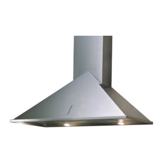
Wall range hoods
Hide thumbs
Also See for SU1:
- Installation instructions manual (12 pages) ,
- Installation instructions manual (32 pages)
Table of Contents
Advertisement
INSTALLATION
INSTRUCTIONS
CARE AND USE MANUAL FOR:
WALL RANGE HOODS
Models covered by this instructions:
SU1 –
SU2
- SUE1 – SU3 – SUE3 – SU4 – SU5 –
SU7
- SUE5
SU22 –
SU23 - SU25
- SU26 SU31 – SU47-P - SU54
SU202/SCH14 – SU207 – SU208 -
SU92 - SU36 - SU97
*** BEFORE INSTALLATION ***
ENSURE THERE IS NO VISIBLE OR HIDDEN DAMAGE SUSTAINED
DURING SHIPPING
*** SHIPPING DAMAGE ***
MUST BE REPORTED WITHIN 5 DAYS OF RECEIPT
Advertisement
Table of Contents

Subscribe to Our Youtube Channel
Related Manuals for Sirius Range Hoods SU1


Summary of Contents for Sirius Range Hoods SU1
- Page 1 INSTALLATION INSTRUCTIONS CARE AND USE MANUAL FOR: WALL RANGE HOODS Models covered by this instructions: SU1 – - SUE1 – SU3 – SUE3 – SU4 – SU5 – - SUE5 SU22 – SU23 - SU25 - SU26 SU31 – SU47-P - SU54 SU202/SCH14 –...
-
Page 2: Installing The Appliance
W A R NI N G Thank you for purchasing a Sirius Range Hood. Please read all the instructions in this manual before installing the appliance. Save these instructions for future reference. Only use this appliance as an exhaust ventilation system for the removal of cooking vapors. -
Page 3: Table Of Contents
TABLE OF CONTENTS BEFORE YOU BEGIN DUCTING External Venting Requirements Duct Run Calculation ELECTRICAL Electrical Supply INSTALLATION Positioning the range hood Marking the fixing holes for the range hood Fixing the Main Support Bracket Chimney installation Hanging the range hood Connecting Electricity and Ducting Connecting Chimneys Connecting the screen... -
Page 4: Before You Begin
B E FOR E Y OU BEG I N The manufacturer declines all responsi- BEFORE YOU BEGIN: It is advisable to test bility in the event of failure to observe the run the range hood before installation. instructions given here for installation, maintenance and suitable operation of BEFORE STARTING –... -
Page 5: Electrical
Maximum Run 6” or 8” 3 1/4 x 10” duct * 100 FT Deduct Each 6” or 8” 90 elbow used 15FT Each 6” or 8” 45 elbow used Each 6” or 8” or 3 1/4 x 10” duct Transition used Each 3”... -
Page 6: Installation
I NST ALL A TION Positioning the Range Hood. Gently tape the template to the wall making Determine the center point of the range sure it has no creases or folds (use a tape hood. This is generally the center of the that will not damage the wall finish). - Page 7 after opening the upper cover of the power box(Fig.b) Only for SU54 Before installing the hood is necessary to and fix the box to the just-fit union with Before to install the hood is necessary to fix the air outlet two fix the tow motor air outlet union with the two screws.
-
Page 8: Chimney Installation
Only for SU202 – SU207 The bracket fixed onto the back of the range hood will drop into the channel on the top of bracket “S” on the wall. Ensu- Fit items “C” before hanging the range hood – refer to figure 5 for positioning re the hood is securely engaged into the support bracket -the range hood must clip in behind the extended lip on the... -
Page 9: Connecting Chimneys
fig. 8 Connect the appropriate length of duc- fig. 10 ting to the fan exhaust point and join up with the ducting to the exte-rior. Do not fix the ducting to the range Figure 9 shows venting directly through hood exhaust outlet with screws-use the wall. -
Page 10: Connecting The Screen
The carbon filter (supplied separately) that absorbs odors is installed behind the aluminium grease filter (refer to Fig 14). fig. 12 fig. 11 Connecting the Screen (SU 202 Only). Before attaching the screen the power unit wipe the face of the flange to en- sure there is no grit present –... -
Page 11: Operating Procedures
O PER A T ING PROC EDURES Read all the instructions before opera- FUNCTION ting the appliance. Save these instruc- tions for future reference. “Manual touch buttons Fig.15” General Advice. A: Light ON/OFF button Ensure that the grease filters are in pla- B: Blower Speed 1 (low) or OFF ce. - Page 12 RC001 Generatiing a new transmiissiion code: The radio control system is provided with ADIO ONTROL preset codes. Should new codes be required, Radio control used for the remote operation proceed as follows: Press simultaneously but- of ducted cooker hoods. tons: TECHNICAL DATA - Alkaline battery powered: 12 V mod.
- Page 13 (within 5 seconds). Leds flashing 6 times indi- cate the procedure is completed. WARNING! This operation deletes perma- nently the preset codes. Emergency button: In the event that the radio control does not work, use the emergency button to switch the appliance off.
-
Page 14: Maintenance
SU Models only: Filter requires washing Use the low speeds for normal use and indicator After 30 hours of use, all the the higher speeds for strong odors and buttons will light up to remind you that fumes. the grease filter should be cleaned. Fol- low the instructions for cleaning filters Generally, the grease filter should be in this booklet. -
Page 15: Light Bulb Replacement
FOR SU1 – SUE1 – SU3 – SUE3 – SU4 – SU5 with a LED bar with same characteristics. – SUE5 – SU22 – SU26 – SU31 – SU47-P Turn blower and lights off. -
Page 16: Warranty
Three Year Limited Warranty YOU MUST REGISTER THE PURCHASE OF YOUR PRODUCT ON LINE AT www.siriuscappe. com/usa/warranty.htm TO CONVALIDATE YOUR WARRANTY. YOU CAN FIND THE DATA OF YOUR HOODS ON A LABEL INSIDE THE HOOD. JUST REMOVE THE GREASE FILTER TO READ IT. WARRANTY SERVICE To qualify for warranty service, you must notify Sirius After sale service at the email ad- dress stated below or call toll free USA 1-877-474-8770 and provide the model number,...
Need help?
Do you have a question about the SU1 and is the answer not in the manual?
Questions and answers