Sign In
Upload
Manuals
Brands
Instron Manuals
Test Equipment
CEAST 9340
Instron CEAST 9340 Manuals
Manuals and User Guides for Instron CEAST 9340. We have
1
Instron CEAST 9340 manual available for free PDF download: Instructions For Use And Maintenance Manual
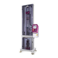
Instron CEAST 9340 Instructions For Use And Maintenance Manual (179 pages)
Drop Weight Impact Testing System
Brand:
Instron
| Category:
Test Equipment
| Size: 4 MB
Table of Contents
Table of Contents
2
Legend
7
1 General Information
8
Equipment Description
11
Introduction
11
Modularity
11
Difference between Instruments
11
Main Parts of Instrument
11
Options
13
Technical Characteristics
14
Layout
16
Safety
17
2 Conditions of Use
18
Authorized Personnel
18
Normal Use Conditions
19
Abnormal Situations
20
3 Operator Work Station
21
Shields
21
Residual Risks
21
4 Transport and Movement
22
Lifting and Handling
22
Movement in Packaging
22
Movement of the Instrument
22
Weight of the Main Parts
23
Check for Possible Damage
23
Storage
23
5 Mounting and Dismantling
24
Dismantling the Packaging Case
24
6 Installation
25
Space and Environment Requirements
25
Space
25
Environment
25
Services
25
Positioning
26
Surface Load in Static Condition
26
Load on Slab
27
Installation Procedure
28
Levelling
32
Stability
33
Cleaning
33
Materials and Products
33
7 Start-Up
34
Instrument, Ceast das 8000 Junior/Ceast 16000 and Pc Connection
34
Electrical Service Connection
34
Pneumatic Service Connection
35
Cryogenic Service Connection
36
8 Use
38
Safety Standards
38
Component Identification
39
Safeties and Their Locations
41
Commands
43
Operations
44
Key Functions
44
Program
45
Program Start - up
47
Navigation through the Program Menus
48
Main Menu
50
Set Temperature
51
Load Parameters
51
Modify Parameters
52
Save Parameters
56
Results
56
Utility
57
Input Password
58
Cycle Counter
59
Fw Version
59
Modify Password
60
Clock
60
Language
61
Service
61
Shutter Moving
62
Striker Release
62
Move to Height
63
Visualize Sensors
63
Visualize I/O
64
Emergencies Synoptic
64
Error Codes in the Program
64
Preparing the Instrument for Testing
65
Replacement of the Stands
65
Replacement of the Specimen Fixtures
66
Replacement of the Striker Holder
74
Replacement of the Weights
76
Replacement of Striker
78
Replacement of the Striker Extension
81
REPLACEMENT of the STRIKER'S HEADS (Interchangeable Head Type)
82
Preparing the Instrument for Tensile-Impact Test Only
86
Program Setting
86
Replacement of the Fixed Height Vice Support Stand
88
Replacement of the Piezoelectric Force Sensor
90
Replacement of the Instrumented Vice for Tensile-Impact
92
Replacement of the Tensile-Impact Specimen
95
Replacement of Striker for Tensile-Impact Tests
97
Support Stands Codes 7520.350 and 7520.351 for Plates of Fiber Reinforced Polymers
98
Introduction
98
Components Identification
98
Disassembly and Assembly of the Support Stands
99
Special-Purpose Tooling for Impact Tests on Pipes
100
Introduction
100
Supports
100
Special Heads for Striker
102
Carry out Test
103
Operating Sequence of an Instrumented Test
103
Screens Shown During Test
104
Test Start
104
Test in Progress
104
Test End
105
9 Maintenance
106
Safety Standards, General Procedure
106
Fuses Replacement
107
Cleaning and Drying Methods
109
Procedure for Loading Firmware Updates
110
Connection
110
Preparation of the Loading Program
110
Loading
113
Loader Upgrade
114
Firmware Upgrade
114
Disconnection
115
Instrument Firmware Check
115
Replacement of the Impact Rollers
116
Greasing the Striker Releasing Mechanism
117
Lubricating the Gearing Chain
118
Verifying the Gearing Chain Tightening
119
10 Spare Parts
120
List of Recommended Spare Parts
120
Ceast 9340 7515.000 and 7516.000
120
List of Spare Parts for Technical Assistance
121
Ceast 9340 Code 7515.000 and 7516.000
121
Environmental Chamber 7510.011
124
Striker Antirebound System Code 7510.002
125
11 Training
126
General Information
126
12 Wiring Diagrams
127
13 Pneumatic Diagrams
148
Appendix A - Ceast 9340 Part List
151
Appendix B - Tooling
154
Appendix C - Tooling for Tensile Impact Test Only
160
Appendix D - Strikers Technical Features
161
Appendix E - Input List
165
Appendix F - Output List
167
Advertisement
Advertisement
Related Products
Instron 1000KPX-J3
Instron 1000KPX-J3D
Instron 1500KPX-J1D
Instron 1500KPX-J3
Instron 2000KPX-J3
Instron 2000KPX-J3D
Instron 2710-11 Series
Instron 2710-111
Instron 2710-112
Instron 2710-113
Instron Categories
Test Equipment
Measuring Instruments
Lifting Systems
Industrial Equipment
Power Tool
More Instron Manuals
Login
Sign In
OR
Sign in with Facebook
Sign in with Google
Upload manual
Upload from disk
Upload from URL